multi phase equivalent circuits - diglet48/restim GitHub Wiki
Note
This information is only useful for traditional stereostim boxes, because the FOC-Stim moved to a different output topology.
Here is a simplified view of a one-phase circuit:
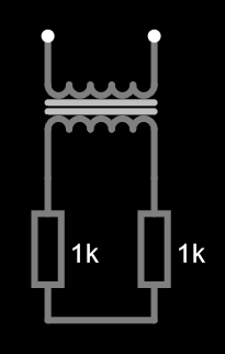
The 1k resistor represents the skin resistance, there is one resistor for the positive lead of the channel and one for the negative lead.
A transformer is a voltage source with an internal resistance, simplified as:
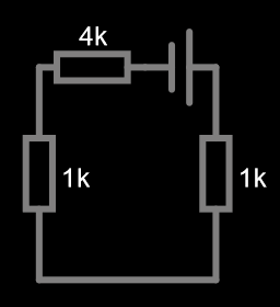
The 4k resistor represents the internal resistance of the transformer.
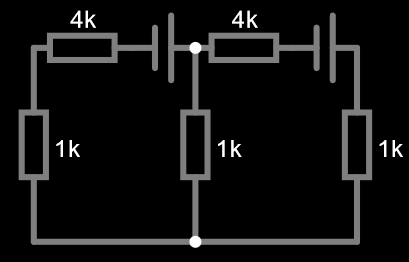
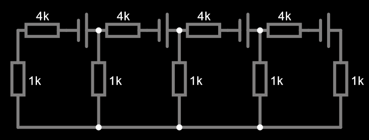
For three-phase:
for 5-phase:
We want to know: given that the voltage over the transformers is
We denote the skin resistance by
Single channel:
three-phase:
four-phase:
five-phase:
Note that
So far we have assumed the skin resistance is the same across all electrodes. This can easily be modified:
The challenge is to create a user interface that allows the user to modify these variables without getting confused.
For single-channel, there is nothing that can be adjusted so that's easy. For three-phase, there are two independent variables (if we ignore volume), which is easy to visualize in a 2D phase diagram. For more phases, it becomes a lot harder.
The diagrams assume first channel positive is connected to second channel negative, this is different from the classic threephase arrangement which connects both negatives together. This is why we use this matrix instead:
Hardware calibration is performed afterwards, refer to source code for details.
Need new measurements
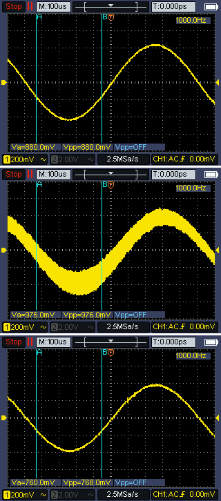
The following experiment was performed with a three-phase circuit, left channel was driven by a 0vrms signal from TPA3116 and the right channel by a sine wave from signal generator.
The signal generator on the right side generates some induced voltage on the left side. The TPA3116 tries to control the voltage back to 0, this causes ~260khz noise with 100mv amplitude. This can be easily filtered on the high side with a 10-100nf ceramic cap.
Below are some scope images, taken at the high side of the left transformer while the right transformer is controlled by the signal generator. From top to bottom: amp off, amp on, amp on + 100nf cap. Note the low voltage used in the test setup magnifies the noise, in actual use the amplitude of the noise is only ~2% of the signal. Consensus seems to be that this doesn't matter.
Although the TPA3116 aggressively tries to drive the left channel down to zero, the actual effect is minor and may only change the actual skin current by 1 or 2%.