hardware calibration - diglet48/restim GitHub Wiki
The problem
Rotating the position with r=1 results in the following output at the electrodes:
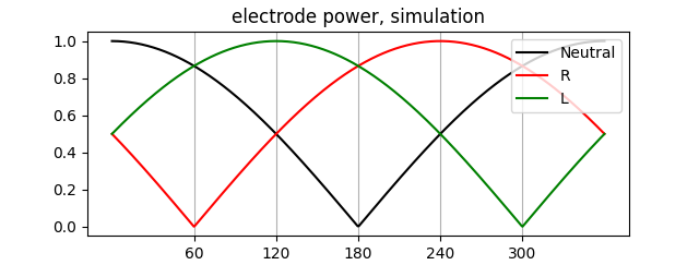
But if we try to measure this on actual hardware with a delta resistor network, we get this:
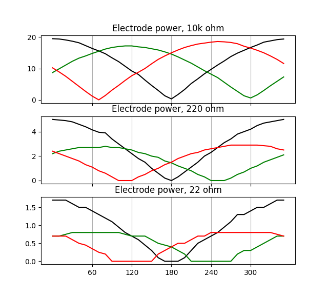
Why is that? The problem lies in the stimbox construction. The L and R electrode are driven by one transformer each, but the Neutral electrode is driven by both transformers. This results in much higher output power at the Neutral electrode. Fortunately this can be mostly fixed in software.
The Model
It turns out we can fix this with a transformation in the alpha-beta space. We hypothesize that the hardware prefers to output current in the alpha axis:
$$T_{HW} = \begin{bmatrix}c & 0 & 0 \ 0 & 1 & 0 \ 0 & 0 & 1 \ \end{bmatrix}, c > 1 $$
Such that:
$$ \begin{bmatrix} \text{output power at N} \ \text{output power at L} \ \text{output power at R} \ \end{bmatrix} = T_{ab} * T_{hw} * T_{ab}^{-1} * \begin{bmatrix}\text{input power at N} \ \text{input power at L} \ \text{input power at R} \ \end{bmatrix}$$
With $T_{ab}$ the alpha-beta transformation. We choose $c = 2.4$:
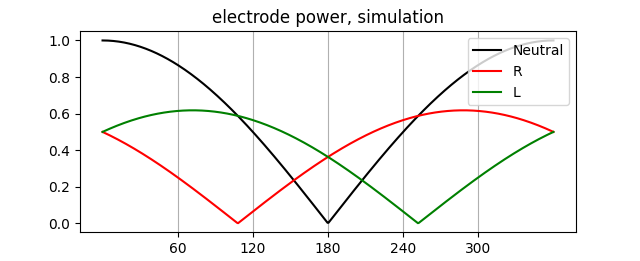
Very similar to the measurements. To nullify the effects of the hardware transformation, we simply multiply by $T_{HW}^{-1}$.
How do we choose the right parameters? Set the position to the Left electrode and attach a voltmeter to the Right audio channel. At the ideal parameters, the voltmeter reads zero. With 220 ohm resistors, I found $c = 2.4$ works well. On a live test subject with a voltmeter, I found $c = 1.73$. But in actual testing I found values around 4 to feel better.
We can also use this to correct for unbalanced electrode resistance. Suppose that the R electrode skin is more sensitive, we would like to decrease the power at R. We can do this by multiplying with a different matrix. See source code for details.
Processing audio
The process above works when dealing with the electrode potentials. What if we only have the audio channels? We define the matrix:
$$P = \begin{bmatrix}1 & -1 & 0 \ 1 & 0 & -1 \ 1 & 1 & 1 \ \end{bmatrix} $$
The idea is that:
$$\begin{bmatrix} \text{Left audio channel} \ \text{Right audio channel} \ 0 \ \end{bmatrix} = P * \begin{bmatrix} i_N \ i_L \ i_R \ \end{bmatrix}$$
Apply correction with:
$$\begin{bmatrix} \text{Corrected left audio channel} \ \text{Corrected right audio channel} \ 0 \ \end{bmatrix} = P * T_{ab} * T_{HW}^{-1} * T_{ab}^{-1} * P^{-1} * \begin{bmatrix} \text{Left audio channel} \ \text{Right audio channel} \ \text{0} \ \end{bmatrix}$$
Audio should be scaled to avoid clipping.