URDF for Robot - dhanushshettigar/Getting-Started-With-ROS2 GitHub Wiki
This guide explains how to create a URDF file, add links and joints, and visualize your robot in ROS. It also covers advanced topics such as adding colors and different types of joints.
- Introduction to URDF
- Your First URDF File
- Adding Color to Your Robot
- Combining Links with Joints
- Types of Joints in URDF
- Creating a Revolute Joint
- Creating a Prismatic Joint
- Learn More
URDF is an XML format used in ROS (Robot Operating System) to describe the physical and kinematic properties of a robot. It defines the robot's links (parts) and joints (connections between parts), allowing ROS to simulate and visualize the robot.
Run the following command in your terminal to create a new URDF file:
touch my_robot.urdfOpen the newly created file with your preferred editor:
code my_robot.urdfAdd the following XML to your my_robot.urdf file to define a simple robot with one box-shaped link.
<?xml version="1.0" encoding="UTF-8"?>
<robot name="my_robot">
   <link name="base_link">
       <visual>
           <geometry>
               <box size="0.6 0.4 0.2"/>
           </geometry>
           <origin xyz="0 0 0" rpy="0 0 0"/>
       </visual>
   </link>
</robot>Launch ROS to visualize the URDF model:
ros2 launch urdf_tutorial display.launch.py model:=/home/<your-pc-name>/Documents/URDFs/my_robot.urdf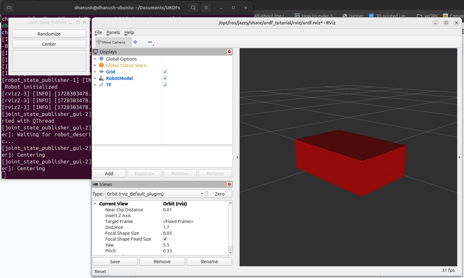
Change the box size, save the file, and rerun the command to see changes.
You can add color to the robot by defining a material and applying it to the link. Update your URDF as follows:
<?xml version="1.0" encoding="UTF-8"?>
<robot name="my_robot">
   <material name="green">
       <color rgba="0 0.5 0 1"/>
   </material>

   <link name="base_link">
       <visual>
           <geometry>
               <box size="0.6 0.4 0.2"/>
           </geometry>
           <origin xyz="0 0 0" rpy="0 0 0"/>
           <material name="green"/>
       </visual>
   </link>
</robot>To create more complex robots, you need to connect links using joints. Here’s how you can define multiple links and joints.
When defining multiple links without a joint, you will encounter an error. Try running the following URDF without a joint and check the screenshot of the error:
<?xml version="1.0" encoding="UTF-8"?>
<robot name="my_robot">
   <link name="base_link">
       <visual>
           <geometry>
               <box size="0.6 0.4 0.2"/>
           </geometry>
       </visual>
   </link>

   <link name="second_link">
       <visual>
           <geometry>
               <cylinder radius="0.1" length="0.2"/>
           </geometry>
       </visual>
   </link>
</robot>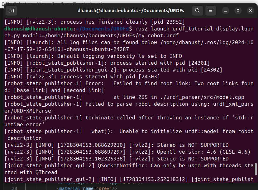
Now let’s add joints between the links to avoid the error:
<?xml version="1.0" encoding="UTF-8"?>
<robot name="my_robot">
   <material name="green">
       <color rgba="0 0.5 0 1"/>
   </material>

   <material name="grey">
       <color rgba="0.5 0.5 0.5 1"/>
   </material>

   <link name="base_link">
       <visual>
           <geometry>
               <box size="0.6 0.4 0.2"/>
           </geometry>
           <origin xyz="0 0 0.1" rpy="0 0 0"/>
           <material name="green"/>
       </visual>
   </link>

   <link name="second_link">
       <visual>
           <geometry>
               <cylinder radius="0.1" length="0.2"/>
           </geometry>
           <origin xyz="0 0 0.1" rpy="0 0 0"/>
           <material name="grey"/>
       </visual>
   </link>

   <joint name="base_second_joint" type="fixed">
       <parent link="base_link"/>
       <child link="second_link"/>
       <origin xyz="0 0 0.2" rpy="0 0 0"/>
   </joint>
</robot>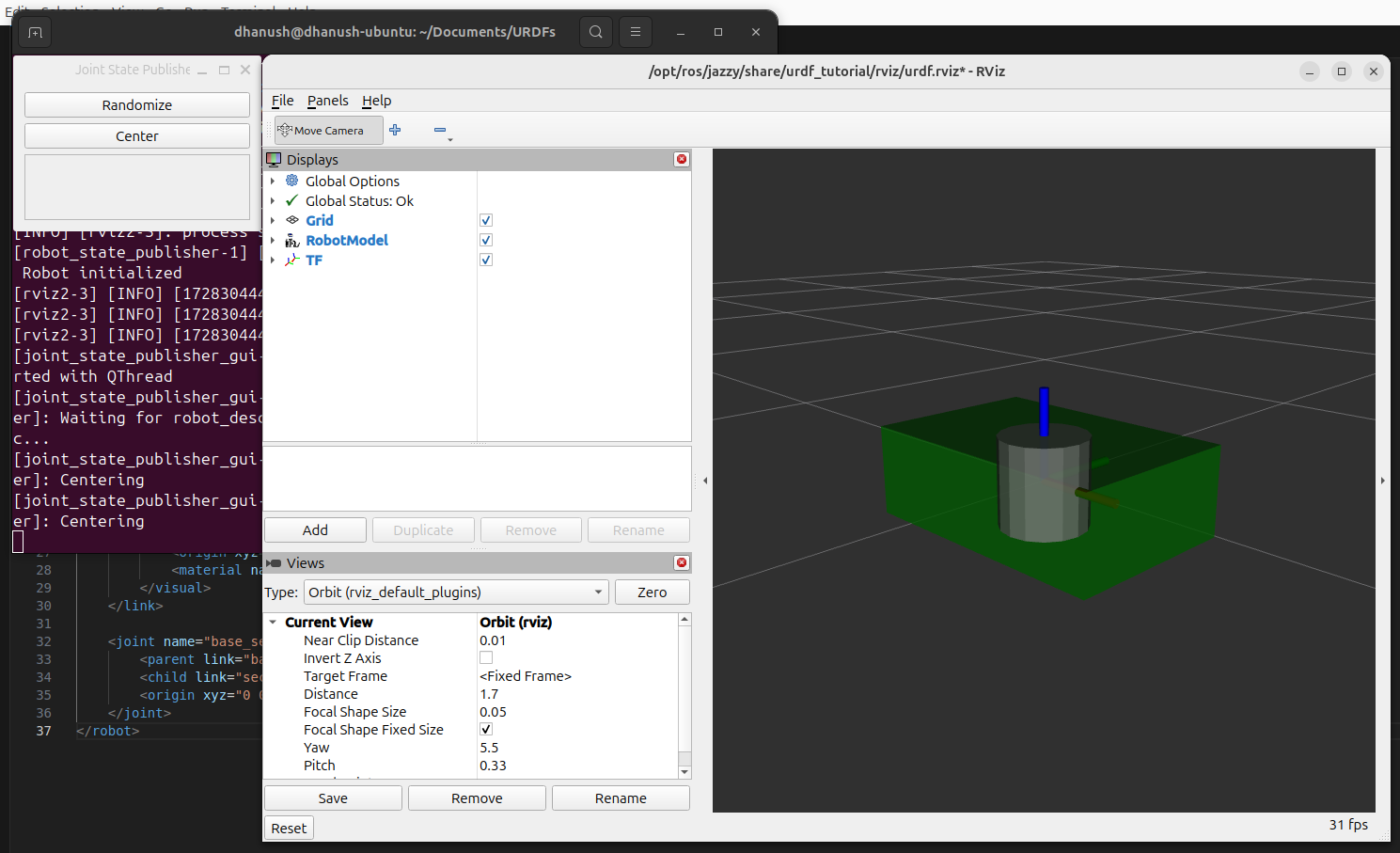
In URDF, joints define how different links of a robot are connected and can move relative to each other. Here are the types of joints that can be specified in URDF:
-
revolute
- A hinge joint that rotates around a defined axis with a limited range of motion.
- The rotation is constrained by the upper and lower limits.
- Example use: a robotic arm elbow joint.
-
continuous
- Similar to a revolute joint, but it can rotate indefinitely without upper or lower limits.
- Example use: a wheel or a robot joint that can rotate fully.
-
prismatic
- A sliding joint that moves along a defined axis.
- The movement is constrained by the upper and lower limits.
- Example use: a linear actuator.
-
fixed
- This is not a joint in the traditional sense, as it does not allow movement. All degrees of freedom are locked.
- No need for attributes like axis, limits, or dynamics.
- Example use: parts of the robot that are rigidly attached to each other.
-
floating
- Allows motion in all 6 degrees of freedom (translation in x, y, z, and rotation about x, y, z).
- Example use: representing free-floating objects in space.
-
planar
- Allows movement in a plane perpendicular to the axis, with translation in x and y and rotation around the z-axis.
- Example use: a sliding platform that moves within a plane.
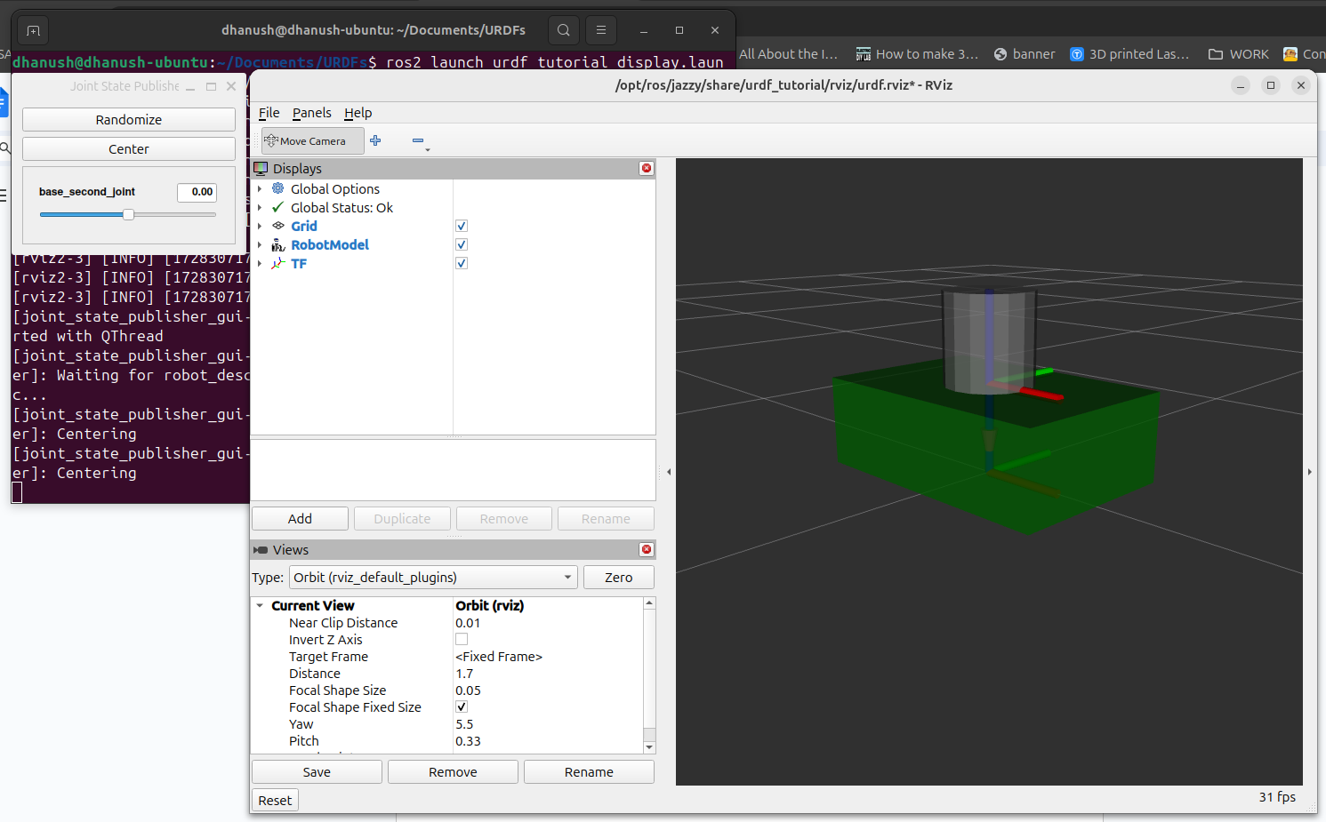
Let’s modify the joint type to a revolute joint to allow rotation between the links:
<?xml version="1.0" encoding="UTF-8"?>
<robot name="my_robot">
   <material name="green">
       <color rgba="0 0.5 0 1"/>
   </material>

   <material name="grey">
       <color rgba="0.5 0.5 0.5 1"/>
   </material>

   <link name="base_link">
       <visual>
           <geometry>
               <box size="0.6 0.4 0.2"/>
           </geometry>
           <origin xyz="0 0 0.1" rpy="0 0 0"/>
           <material name="green"/>
       </visual>
   </link>

   <link name="second_link">
       <visual>
           <geometry>
               <cylinder radius="0.1" length="0.2"/>
           </geometry>
           <origin xyz="0 0 0.1" rpy="0 0 0"/>
           <material name="grey"/>
       </visual>
   </link>

   <joint name="base_second_joint" type="revolute">
       <parent link="base_link"/>
       <child link="second_link"/>
       <origin xyz="0 0 0.2" rpy="0 0 0"/>
       <axis xyz="0 0 1" />
       <limit lower="-1.57" upper="1.57" velocity="100" effort="100"/>
   </joint>
</robot>
You can change the axis attribute to rotate around different axes (e.g., x or y).
A prismatic joint allows linear movement (sliding). Modify the joint as follows:
<joint name="base_second_joint" type="prismatic">
   <parent link="base_link"/>
   <child link="second_link"/>
   <origin xyz="0 0 0.2" rpy="0 0 0"/>
   <axis xyz="1 0 0" />
   <limit lower="0" upper="0.2" velocity="100" effort="100"/>
</joint>
Now, the second link can slide along the x-axis between 0 and 0.2 meters.
For more details on URDF, check out the URDF Documentation and explore different joint types and robot configurations.