Custom Robot (2 Wheels) - dhanushshettigar/Getting-Started-With-ROS2 GitHub Wiki
This tutorial demonstrates how to design a simple robot using URDF (Unified Robot Description Format). The robot includes a chassis, two wheels, and a caster wheel. Below are the steps involved, along with the full XML code snippets.
- Create a Chassis (Base Link)
- Add the Right Wheel
- Align the Right Wheel
- Add the Left Wheel
- Add the Caster Wheel
- Conclusion
The chassis serves as the central structure (base) of the robot. We define it as a box-shaped link. The origin is offset slightly to ensure it rests above the ground.
<robot name="ros_bot">
   <material name="blue">
       <color rgba="0 0 0.5 1"/>
   </material>

   <link name="base_link">
      <visual>
          <geometry>
              <box size="0.6 0.4 0.2"/>
          </geometry>
          <origin xyz="0 0 0.1" rpy="0 0 0"/>
          <material name="blue"/>
      </visual>
   </link>
</robot>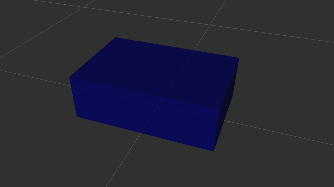
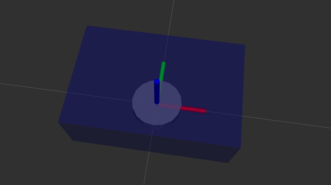
A cylinder geometry is used to represent the right wheel. We use a continuous joint type, which allows the wheel to rotate continuously.
   <material name="grey">
       <color rgba="0.5 0.5 0.5 1"/>
   </material>

   <link name="right_wheel_link">
      <visual>
          <geometry>
              <cylinder radius="0.1" length="0.05"/>
          </geometry>
          <origin xyz="0 0 0" rpy="0 0 0"/>
          <material name="grey"/>
      </visual>
   </link>

   <joint name="base_right_wheel_joint" type="continuous">
       <parent link="base_link"/>
       <child link="right_wheel_link"/>
       <origin xyz="0 0 0" rpy="0 0 0"/>
       <axis xyz="1 0 0"/>
   </joint>
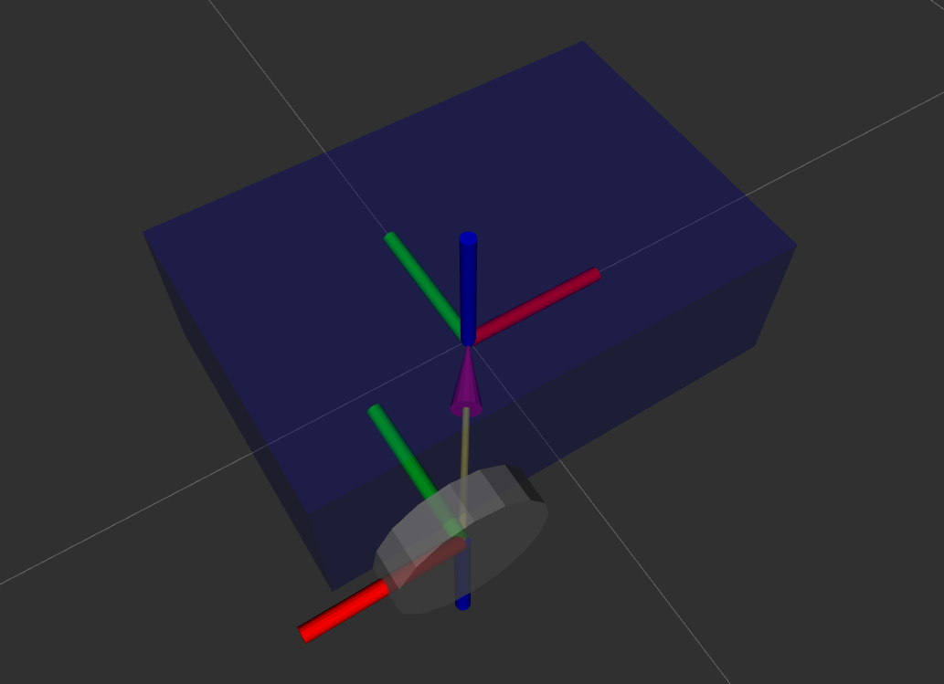
The right wheel is now rotated 90 degrees along the x-axis (rpy="1.57 0 0") so it aligns correctly with the chassis. We also position it on the right side of the base link using an offset in the origin tag.
   <link name="right_wheel_link">
      <visual>
          <geometry>
              <cylinder radius="0.1" length="0.05"/>
          </geometry>
          <origin xyz="0 0 0" rpy="1.57 0 0"/>
          <material name="grey"/>
      </visual>
   </link>

   <joint name="base_right_wheel_joint" type="continuous">
       <parent link="base_link"/>
       <child link="right_wheel_link"/>
       <origin xyz="-0.15 -0.225 0" rpy="0 0 0"/>
       <axis xyz="0 1 0"/>
   </joint>
Similar to the right wheel, the left wheel is defined with a cylinder geometry. We rotate it 90 degrees for alignment and place it on the left side of the base.
   <link name="left_wheel_link">
      <visual>
          <geometry>
              <cylinder radius="0.1" length="0.05"/>
          </geometry>
          <origin xyz="0 0 0" rpy="1.57 0 0"/>
          <material name="grey"/>
      </visual>
   </link>

   <joint name="base_left_wheel_joint" type="continuous">
       <parent link="base_link"/>
       <child link="left_wheel_link"/>
       <origin xyz="-0.15 0.225 0" rpy="0 0 0"/>
       <axis xyz="0 1 0"/>
   </joint>
A sphere geometry represents the caster wheel, providing stability to the robot. The caster wheel is fixed to the base with a fixed joint since it doesn’t rotate or move independently.
   <link name="caster_wheel_link">
      <visual>
          <geometry>
              <sphere radius="0.05"/>
          </geometry>
          <origin xyz="0 0 0" rpy="0 0 0"/>
          <material name="grey"/>
      </visual>
   </link>

   <joint name="base_caster_wheel_joint" type="fixed">
       <parent link="base_link"/>
       <child link="caster_wheel_link"/>
       <origin xyz="0.2 0 -0.05" rpy="0 0 0"/>
   </joint>
</robot>
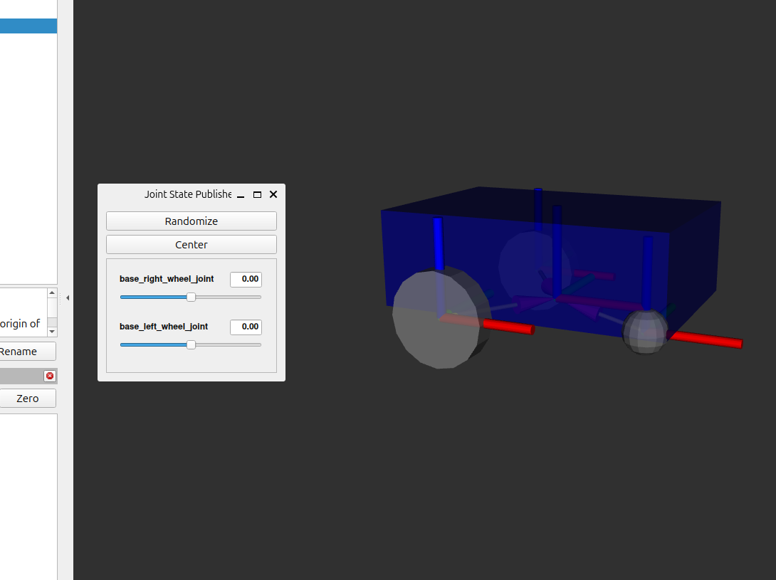
This URDF file defines a basic two-wheeled robot with a chassis, left and right wheels, and a caster wheel for stability. You can visualize this robot using RViz