Hardware Design - dawsonjon/PicoRX GitHub Wiki
Please note, this wiki is no longer maintained, you can find the latest documentation on readthedocs.
Hardware Design
The design aim for the hardware is to make the design as simple and cheap as possible without compromising the performance too much. I have designed a PCB that expands on the basic concept to include a preamplifier and a bank of low-pass filters. To check out the details you can look at the full Schematics in pdf format, but I will walk through some of the details here.
Raspberry Pi Pico
The heart of the receiver is a Raspberry Pi Pico. The onboard ADC samples at 500kSamples/s giving us 250kHz of bandwidth. The 12-bit ADC has a theoretical dynamic range of 72 dB, but it won't be that good in reality. An SSB signal only needs 2.5kHz of bandwidth. We can exchange our excess bandwidth for increased dynamic range improving the overall sensitivity. An oversampling ratio of 100 gives us an extra 20dB, equivalent to adding 3 extra bits. This gives a theoretical dynamic range of 92dB in SSB mode. The ADC has an input range of 0 to 3.3V. With no amplification, that represents a range of -78 dBm to 14 dBm.
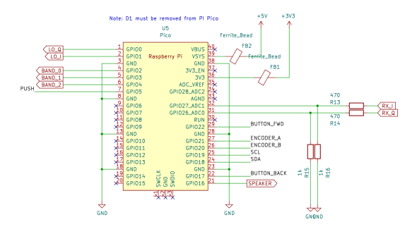
The Raspberry Pi Pico has an onboard switched mode regulator, which allows the Pico to be easily powered by batteries. This design uses 3xAAA batteries. It is possible to add additional external components to the pi pico to allow the device to be powered from batteries, or the USB power supply. This design is primarily intended to be a portable standalone radio, with the USB connection providing the ability to program the flash. To avoid the need to add additional components, I opted to remove D1 from the pico instead. This prevents the possibility of contention between the USB supply and the batteries.
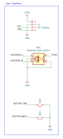
User Interface
There isn't anything particularly unusual about the user interface. A 128x64 OLED display uses an ssd1306-based I2C interface. These are fairly ubiquitous these days and have replaced the HD44780 as the go-to cheap/simple display. The I2C interface certainly helps reduce the pin count. Cost is a key driver, I could have replaced the rotary encoder with a pair of push buttons to save cost, but I think this would be a step too far. It wouldn't feel like a radio without a proper tuning knob. Ideally, I would have liked to use something a bit more compact, a thumbwheel-based rotary encoder mounted on one edge would have been ideal. Although there do seem to be some around, they seem to be quite hard to find. This directional navigation scroll wheel also caught my eye, but in the end, cost won out and I went with a standard encoder.
PWM audio
At first, I considered using an LM386 (or similar) audio amplifier to drive the headphones or a small speaker. It turns out that the PWM is perfectly capable of driving headphones or a small speaker directly. A 100uF capacitor blocks DC, the larger the capacitance the better the DC response, but in this application 100uF is probably overkill. The RP2040 has a maximum drive strength of 12mA. The 100-ohm resistor serves as a current limiting resistor and one-half of an RC low-pass filter. With a peak voltage of 1.65v, and assuming an internal resistance of about 40 ohms, the maximum current into a 32-ohm load is 1.65/(100+40+32) = 9.5mA and with an 8-ohm load is 1.65/(100+40+8) = 11.1mA.

If a better speaker were needed, the TPA2012 looks like the ideal modern replacement for the LM386, and would be ideal for battery-powered applications. The output also works well with PC speakers, but watch out for the drive level being significantly higher than the usual 100mV pk-pk.
QSD Detector (Tayloe Detector)
The design uses a "Tayloe" Quadrature Sampling Detector (QSD) popularised by Dan Tayloe. It is used in many SDR receivers, and for good reason. In this design, the select inputs to the analogue switch are driven directly by the Raspberry Pi Pico, the PIO feature of the RP2040 is capable of generating a quadrature oscillator at frequencies up to 30MHz without software intervention. The resistor values have been chosen to give a gain of 1000 or 60 dB. This gives a theoretical input range at the input to the QSD of -138 dBm to -46 dBm. The capacitor values have been chosen to give a cut-off frequency of about 60kHz and a bandwidth of 120kHz. QSD is effectively acting as the anti-aliasing filter, so a degree of oversampling helps. The gain and bandwidth requirements require a fast op-amp. The LT6231 is a popular choice in this type of SDR because of its low noise, it is fast enough to cope with the larger bandwidth used in this design compared to most SDRs. The newer LTC6227 op-amp is recommended for new designs and is even better.
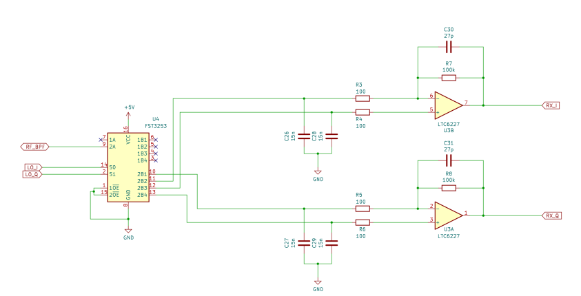
One potential weakness of this design is the potential of aliasing in the ADC. This isn't an issue for SDRs that use sound cards or audio ADCs, they usually include very good antialiasing filters. A potential improvement would be to include an active low-pass filter. This could make use of a more basic (and cheaper) op-amp. There is also a potential to save cost by cascading several cheaper op-amps sharing the gain between them, the gain bandwidth product at each stage could be much lower, and the noise performance of the later amplifiers is less critical.
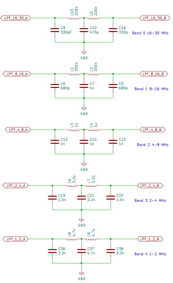
Low Pass Filters
The Tayloe detector uses a switch rather than an analogue mixer, this gives similar behaviour to mixing the incoming RF with a square wave. This means that the QSD is sensitive to signals at odd harmonics of the fundamental, the strongest of which is at 3 times the tuned frequency. This design employs low-pass filters to strongly attenuate the odd harmonics. A bank of 5 filters covers the frequency range from 1MHz to 30MHz. The bands each cover an octave, in the 1MHz to 2 MHz band, a cutoff frequency of 2MHz attenuates the third harmonic which could be between 3MHz and 6MHz. As the frequency increases, the width of the band can be doubled, so the range from 1MHz to 30MHz can be covered with 5 filters. To cover the full LW and MW range, I would have needed at least 3 more filters, this seems excessive considering the limited number of stations in this part of the spectrum, so I decided to just live with the possibility of interfering at odd harmonics in this range. There is no reason why an additional filter couldn't be added by a user interested in these bands, it could even be built into a magnetic loop or ferrite antenna.
In practice, strong local AM stations can cause interference, since these tend to be at lower frequencies the low-pass filters do little to attenuate them. Bandpass filters would have given a better performance. I found that fitting an external AM band-stop filter greatly improved the performance in the SW frequency bands.
There are a few online tools that can be used to calculate the filter values, I used this one
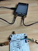
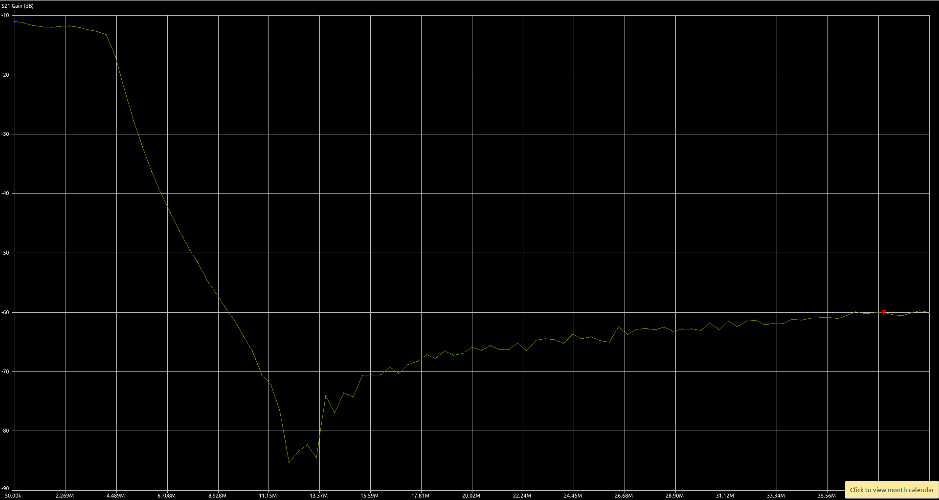
I measured the filter response using a nanovna. This takes a lot of guesswork out of the design. I made a direct connection to the filters having partially assembled the PCB.
This one has the desired 4MHz cutoff frequency and an attenuation of more than 60dB in the stop band. In the pass band, there is an insertion loss of about 10 dB. This gives a theoretical power range of around -128 dBm to -36 dBm.
Preamplifier
In a LW/MW/SW band there are high levels of atmospheric noise. Arguably, a preamplifier isn't necessary. If we could achieve the theoretical range of -128 dBm to -36 dBm, that would give us all the sensitivity we need. In practice, the ADC has internal noise of about 20dB. An MDS of a little better than -100dBm might be a more realistic figure.
A good rule of thumb is that the receiver should be able to "see" the antenna noise to give the best chance of resolving weak signals. A good way to check this is to look for a rise in the noise floor of about an s-point when connecting the antenna.
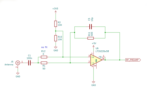
With a loft-mounted wire antenna, I found that the receiver was sensitive enough. For portable use, however, a more compact antenna is desirable. I had good results with a youloop antenna, but I needed to add a low-noise amplifier to get good results. I used a typical 20dB MMIC-based LNA with the prototype. I thought about using an MMIC amplifier like a MAR6. Instead, I opted to use the LTC6226 op-amp (a single amplifier version of the LTC6227 amplifier used in the QSD). This low-noise amplifier has enough GBP to provide 20dB gain over the 30MHz bandwidth. The amplifier uses an inverting configuration with a 50 ohm input impedance. The feedback network includes a capacitor and resistor to give a low-pass-filter behaviour with a cutoff frequency of 30MHz.
With the LTC6226 preamplifier, I can hear plenty of weak signals using the youloop antenna but I do now find that strong local AM stations overload the receiever causing heavy clipping. There may be scope to tweak the gain in the preamplifier to find a better compromise, that allows most signals to be received. Perhaps a switchable attenuator could be added to make the receiver more versatile.
Enclosure
Enclosures often end up being one of the most expensive components in an electronic project. However, it is now possible to have PCBs made very cheaply in a range of colours with contrasting silk-screen printing, they can be accurately machined and are extremely strong. In short, they make ideal front (and back) panels. I opted for a PCB sandwich style of construction to build a cheap, robust and reasonably smart-looking device.