BBSHD Controller PCB - danielnilsson9/bbs-fw GitHub Wiki
Hardware Revisions
| Revision | MCU | Released | Comment |
|---|---|---|---|
| V1.4 | STC15W4K56S4 | ~2017 | V1.3 printed on PCB |
| V1.5 | IAP15W4K61S4 | ~2019 | V1.4 printed on PCB |
Nothing noticeable changed on PCB:s, pin compatible MCU.
Microcontrollers
STC
Running at 5.0V
| PIN | Type | Function | Comment |
|---|---|---|---|
| P0.6 | IN | Hall W | Hall effect sensor signal W. |
| P1.0 | UART2 | RX | UART rx line for communication with NEC MCU. |
| P1.1 | UART2 | TX | UART tx line for communication with NEC MCU. |
| P1.3 | ADC3 | Throttle input | 0-5V. 9K external pulldown. |
| P1.6 | ADC6 | Battery voltage | Battery voltage reading. |
| P1.7 | ADC7 | Controller temperature | Controller temperature reading, see schematic. |
| P2.0 | OUT | Motor power enable | Signal to NEC MCU to enable motor power. |
| P2.1 | OUT | Motor control enable | Signal to NEC MCU to enable motor control (should be kept high). |
| P2.2 | IN | Speed sensor | 5V. Speed sensor signal. |
| P2.3 | OUT | External lights | Controls signal for external lights. Active low. |
| P2.4 | IN | Brake | 5V. Active low. Also connected directly to NEC MCU. |
| P2.6 | IN | Gear Sensor | 5V. Active low. |
| P3.0 | UART1 | RX | 5V. External UART rx line for display communication. |
| P3.1 | UART1 | TX | 5V. External UART tx line for display communication. |
| P3.4 | IN | Hall V | Hall effect sensor signal V. |
| P4.4 | OUT | Motor control enable | Signal to NEC MCU to enable motor control (should be kept high). |
| P4.5 | IN | PAS 1 | Pedal assist sensor signal 1. |
| P4.6 | IN | PAS 2 | Pedal assist sensor signal 2. |
| P5.0 | IN | Hall U | Hall effect sensor signal U. |
| P5.1 | OUT | External lights enable | Control transistor applying power to external lights PCB. |
NEC
Running at 5.0V
| PIN | Type | Function | Comment |
|---|---|---|---|
| P22 | IN | Motor control enable | Signal from STC MCU to enable motor control (should be kept high). |
| P23 | IN | Motor control enable | Signal from STC MCU to enable motor control (should be kept high). |
| P25 | ADC | Current Sense | Via shunt resistors and LM358 OPAMP. |
| P70 | OUT | Status led | Blinking on/off on normal operation. |
| P73 | UART | TX | Connected to RX UART2 (P1.0) on STC MCU. |
| P74 | UART | RX | Connected to TX UART2 (P1.1) on STC MCU. |
| P120 | IN | Hall U | Hall effect sensor signal U. |
| P121 | IN | Hall W | Hall effect sensor signal W. |
| P122 | IN | Hall V | Hall effect sensor signal V. |
| P150 | IN | Motor power enable | Signal from STC MCU to enable motor power. |
| P151 | IN | Battery voltage | Also connected to STC MCU |
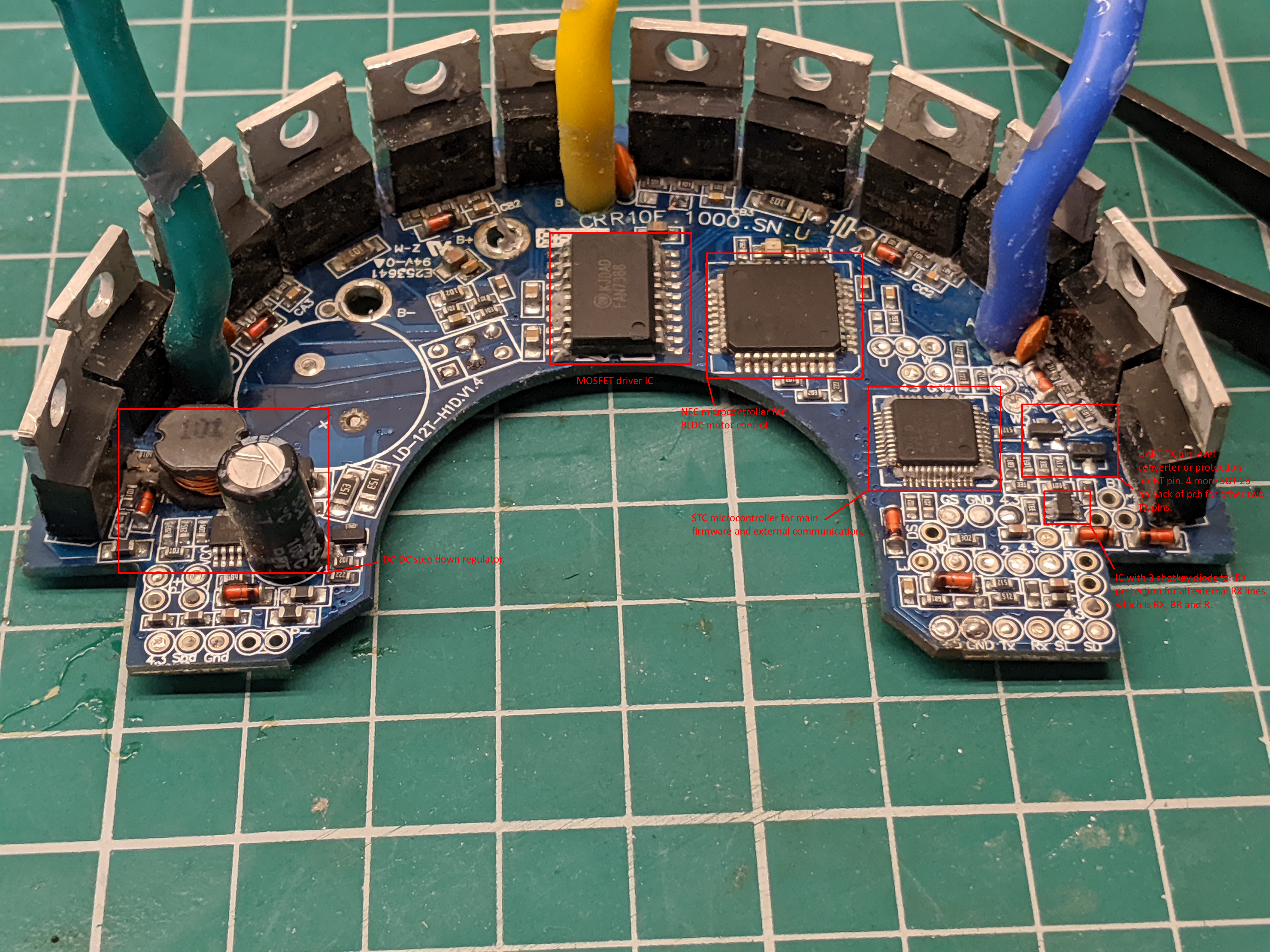
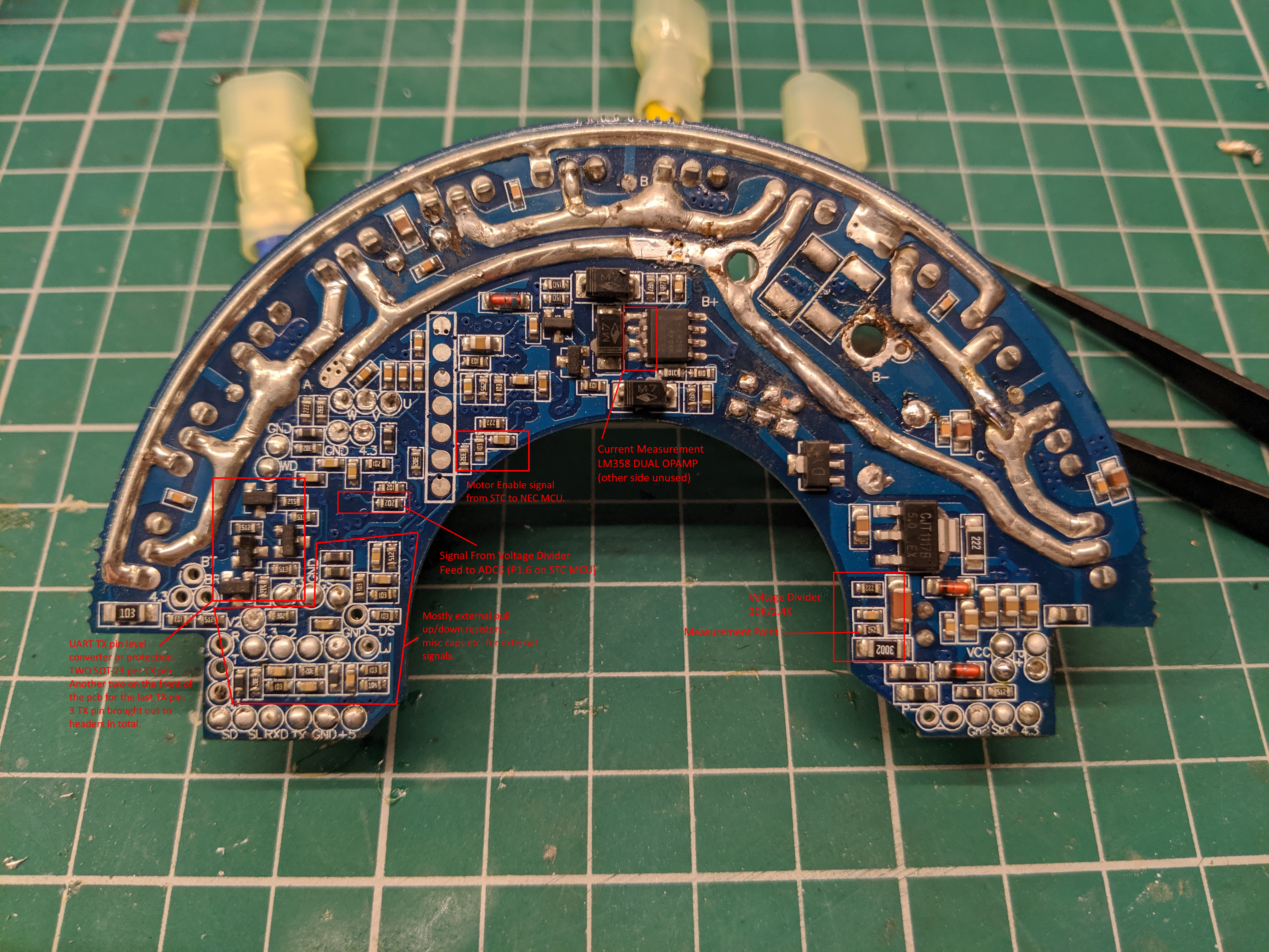
Photos
More detailed photos are available in the wiki repository, clone this git repository:
https://github.com/danielnilsson9/bbshd-fw.wiki.git