Tutorial E puck for ROS2 Beginners - cyberbotics/webots_ros2 GitHub Wiki
E-puck is a miniature mobile robot originally developed at EPFL for teaching purposes by the designers of the successful Khepera robot.
- E-puck

Here you will find instructions on how to use the e-puck ROS2 API.
This documentation is common for the physical (epuck_ros2) and simulated (webots_ros2_epuck) robot.
Getting Started
Please make sure that you have the robot driver running. This will ensure that access to sensors and actuators is exposed through the ROS2 API.
Simulated Robot
The launch file starts Webots and ROS2 driver:
ros2 launch webots_ros2_epuck robot_launch.py
For convenience, you can also launch rviz, e.g.:
ros2 launch webots_ros2_epuck robot_launch.py rviz:=true
In RViz2, you may want to change
Global Options > Fixed Frametoodomif you don't have a publisher publishing transforms betweenodomandmapframes.
Physical Robot
This launch file starts the e-puck driver for the physical robot:
ros2 launch epuck_ros2 robot_launch.py
Tutorials
When you have the ROS2 driver running you can proceed with the tutorials.
Infra-red, Light Sensors, and LEDs
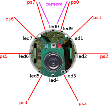
E-puck2 has 8 infra-red sensors (named as ps0-7) all of which are mapped to the same name ROS2 topics of type sensor_msgs/Range.
Therefore, you can obtain a distance from a sensor as follows:
ros2 topic echo /ps1
Besides infrared sensors, e-puck2 is upgraded with a long-range ToF sensor positioned just above the camera.
Data from this sensor is also exposed through the sensor_msgs/Range topic with the name tof.
All distance sensors are combined to create sensor_msgs/LaserScan so you can use it directly in SLAM packages. You can test it as:
ros2 topic echo /scan
The same infra-red sensors act as light sensors. In the ROS2 driver, data from the sensors is published as sensor_msgs/Illuminance message (unit is lux) and you can subscribe to it as follows:
ros2 topic echo /ls1
Notice in the image above, there are 8 LEDs as well-positioned around the robot.
LEDs led0, led2, led4 and led6 can be only turned on or off, while LEDs led1, led3, led5 and led7 have controllable RGB components.
Therefore, in the case of binary LEDs, you can test them as:
ros2 topic pub /led0 std_msgs/Int32 '{ "data": 1 }'
ros2 topic pub /led0 std_msgs/Int32 '{ "data": 0 }'
and RGB as:
ros2 topic pub /led1 std_msgs/Int32 '{ "data": 0xFF0000 }'
ros2 topic pub /led1 std_msgs/Int32 '{ "data": 0x000000 }'
where 3 lower bytes of Int32 represent 3 bytes of R, G, and B components.
Velocity Control
Standard geometry_msgs/Twist topic with name /cmd_vel is exposed for velocity control.
ros2 topic pub /cmd_vel geometry_msgs/Twist "linear:
  x: 0.1
  y: 0.0
  z: 0.0
angular:
  x: 0.0
  y: 0.0
  z: 0.0"
Note that only
linear.xandangular.zare considered as e-puck2 is a differential wheeled robot.
Odometry
Standard ROS2 messages nav_msgs/Odometry are used to publish odometry data You can subscribe to it with:
ros2 topic echo /odom
In case you are not interested in covariance matrices, you can use the --no-arr parameter to hide arrays:
ros2 topic echo --no-arr /odom
You can also visualise odometry in rviz:
ros2 launch webots_ros2_epuck robot_launch.py rviz:=true
In RViz2, you may want to change
Global Options > Fixed Frametoodomif you don't have a publisher publishing transforms betweenodomandmapframes.
Camera
Camera data and details are described through camera (type sensor_msgs/Image) and camera/camera_info (type sensor_msgs/CameraInfo) topics.
Compared to the physical robot driver there is no sensor_msgs/CompressedImage since the images are not meant to be transferred through a network.
You can run rqt , navigate to Plugins > Visualization > Image View and for topic choose /camera.
Note that the image encoding is BGRA.
IMU
There are 3D accelerometer and 3D gyro hardware on e-puck2.
You can access to this data through imu topic (type sensor_msgs/Imu), e.g.:
ros2 topic echo --no-arr /imu
Ground Sensors
Ground sensors come as an optional module for e-puck2. If the module is present, the ROS2 driver will automatically detect it and publish data. You can test them as:
ros2 topic echo /gs1
To put the ground sensor module, select groundSensorsSlot in e-puck2 robot tree, click + button and find E-puckGroundSensors (check out this image).
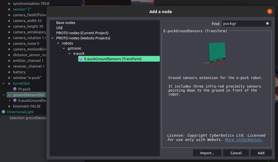
Transformations
Dynamic transformations are only used for the odometry and you can show it as:
ros2 topic echo tf
All other transformations are static and they are exposed as latched topics, so you can show them with the following command:
ros2 topic echo --qos-profile services_default --qos-durability transient_local tf_static
For general access to transformations you can use tf2_monitor:
ros2 run tf2_ros tf2_monitor
or if you want to read transformation between arbitrary two coordinate frames in a tree:
ros2 run tf2_ros tf2_echo odom map
Navigation
ROS2 Navigation2 stack (see this figure) allows us to move robot from point A to point B by creating a global plan and avoiding local obstacles.
It is integrated into the e-puck example and you can run it by including the nav parameter:
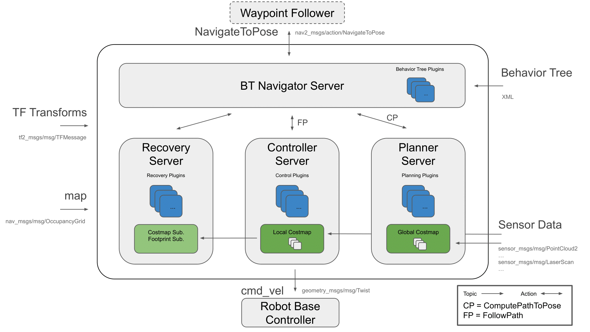
ros2 launch webots_ros2_epuck robot_launch.py rviz:=true nav:=true
or without RViz2 you can just publish a desired pose:
ros2 topic pub -1 /goal_pose geometry_msgs/PoseStamped \"
pose:
  position:
    x: 0.3
    y: 0.0
    z: 0.0
  orientation:
    x: 0.0
    y: 0.0
    z: 0.0
    w: 1.0
"
By default, the navigation will use a epuck_world_map.yaml map available in /webots_ros2_epuck/resource.
To change the map, you have to use the map argument:
ros2 launch webots_ros2_epuck robot_tools_launch.py rviz:=true nav:=true map:=/path/to/your/map.yaml
This example will work properly only for ROS2 Foxy Fitzroy and later.
Mapping
Unfortunately, default SLAM implementation doesn't work well with e-puck.
Therefore, we created a simple mapping node that relies purely on odometry.
You can launch it as a part of the e-puck example launch file by adding the mapper parameter:
ros2 launch webots_ros2_epuck robot_launch.py rviz:=true mapper:=true
Drive the robot around (with e.g. teleop_twist_keyboard) to discover as much of the map as possible.
Once you are satisfied with the result you can save the map as:
ros2 run nav2_map_server map_saver_cli -f $HOME/Pictures/map
Differential Drive Calibration
Based on the rotation speed of each wheel and two constants, distance between the wheels and wheel radius, we can calculate the position of the robot in the local frame. Therefore, the precision of the position estimation depends a lot on the distance between the wheels and the wheel radius. Those constants can vary from robot to robot and here we provide a tool to help you to calibrate it (this technique is very similar to the one proposed in "Measurement and Correction of Systematic Odometry Errors in Mobile Robots").
First, we want to measure wheel radius and we can achieve it by letting the robot move in a straight line:
ros2 run webots_ros2_epuck drive_calibrator --ros-args -p type:=linear
If the robot overshoots the given distance (default 0.1335m), we should increase the wheel radius, otherwise decrease it:
ros2 param set /epuck_driver wheel_radius 0.0215
Second, to calibrate the distance between the wheel we can let the robot rotate in the spot:
ros2 run webots_ros2_epuck drive_calibrator --ros-args -p type:=angular
If overshoots, the given number of rotations (default 4) then decrease the distance between the wheels, otherwise increase it.
ros2 param set /epuck_driver wheel_distance 0.0514
Third, repeat those two steps until you are satisfied with the precision.
Note that you can measure distance by a tool (e.g. ruler), it is a good initial guess, but with the technique described above, you will achieve much better results. According to the paper, such techniques can significantly reduce systematic errors (page 4 and 23).