5. Main Frame Construction part A - crunchysteve/TriceratopsTwo GitHub Wiki
Description & Parts
Most of the main frame, which is where the seat mounts, what the crossmember pivots on and is connected to the front bracket (equivalent of the bottom bracket on a bicycle) at the front and the rear triangle at the rear. In this chapter I'm going to focus on the steerer head, frame parts and seat mounts. Building/modifying (depending on full built or donor bike parts) and fitting the rear, as well as the front bracket, tierod brackets and chain pulley mounts, will all come in a later chapter. The aim in these earlier chapters is to get the trike to a billy cart stage for testing and ensuring it's running true before we add other parts. There's no point continuing the build to a complete trike, only to find you've borked the geometry enough to make it run askew. At least not until you've built a few and have worked out the most reliable way to assemble them.
(But you can't build these commercially, remember, or too many of them. If a friend wants one, point them to kazebikes.com. If they can't afford that, help them build their own. You may run foul of patent law, otherwise. YMMV.)
We need more 35mm x 1.6 SHS tubing, 1100mm, give-or-take, depending on your steerer tube length and stack height of your steerer bearings, of 38mm x 3 EHS tubing (or salvage a head tube from a donor bike and clean up) and 3x 150mm lengths of 20mm x 1.6 SHS for seat mounts.
Cutting & Welding the "Spine"
The rear-main tube is shaped from a 600mm length of 35mm square tube. At 200mm from the front end of this tube, the end that gets welded to the head tube, we need to mark a line down each side, perpendicular to the top and bottom. Then, from the top of this line, at a 6° line moving away from our first line forwards, then the same again, only 6° backwards to mark the v-cut we need to make in this tube. I printed adhesive labels for all my angle cuts, as this turned out to be a very good way to mark accurate v-cuts in the bottom side of this tube. 6° either side of the perpendicular line at 200mm means that, when we bend and weld this piece, we'll get a 12° bend in the pipe. If you have access to the right kind of hydraulic pipe bender, one that will stop the sides from splaying and buckling outwards, do it that way. I don't.
Then we'll repeat this for a 500mm length of 35mm pipe, only we're putting the bend at 100mm from the end that will be welded to the steerer head tube. Again, we're aiming for a 12° bend, only this one bends up, not down. Those 2 M8 nuts, shown at the front end of the pedal spar, are welded over 2 holes drilled to slightly larger than the holes in the nuts. Later, when we build the "front bracket" spar, we'll clamp it with 2 M8 grub screws, tightened through these nuts, to hold the front bracket firmly in place as you pedal.
The next cuts in these two tubes get a bit complex, as this image shows.
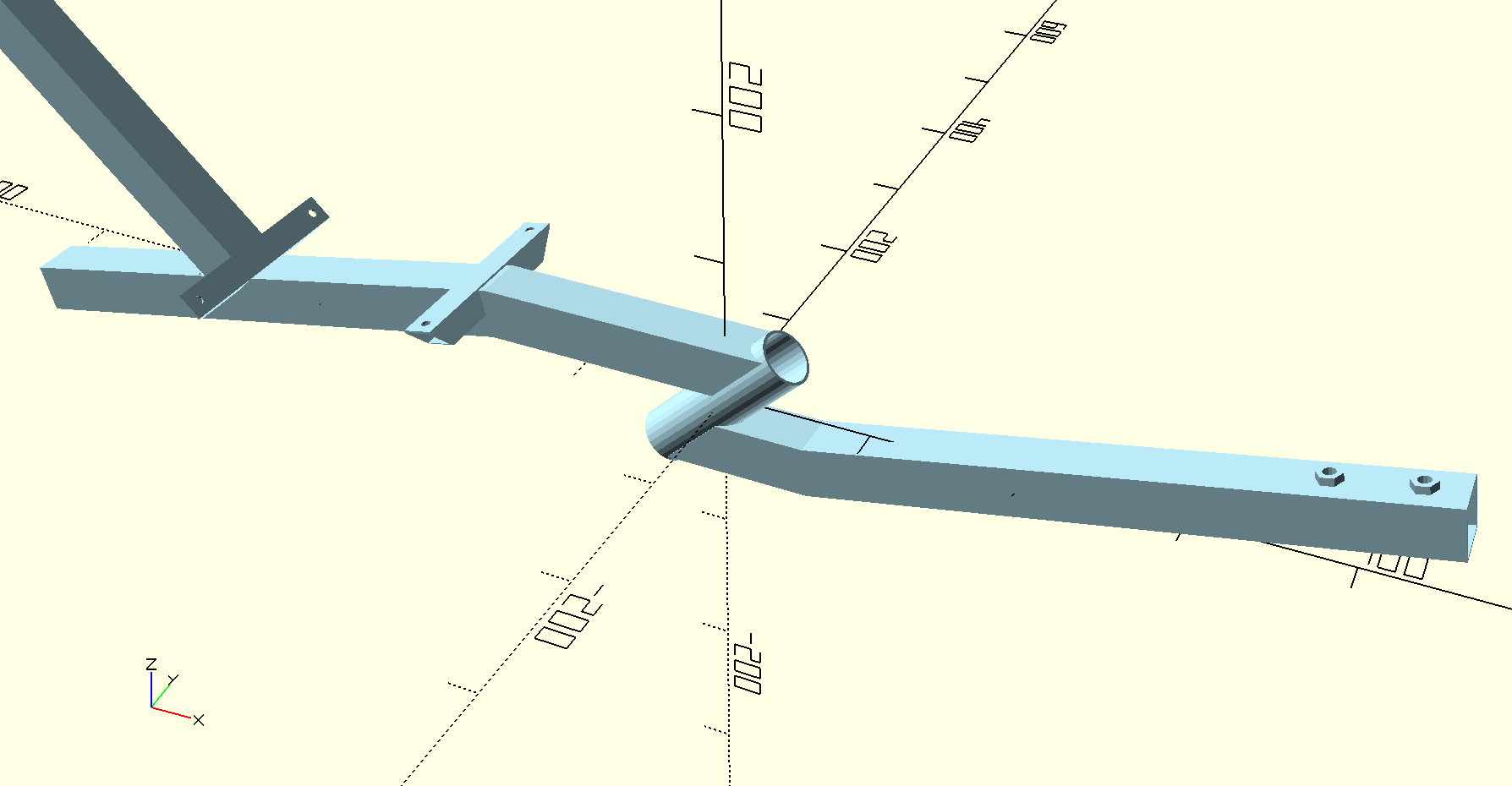
The short part of the bent rear tube comes horizontally to the top end of the head tube, which has a 45° forward tilt (a "negative head angle"), while the short part of the front bent tube leaves the bottom of the head tube horizontally, then bends up. This allows us an ergonomic seat angle and an ergonomic pedal height based on leg length. It also makes the welds to the head tube very complex. I solved this marking and cutting of the square tubes again with adhesive labels, but found an even better way was to 3D print a sleeve that slips over the 35mm SHS and allows me to pencil mark the circular cuts in the top and bottom faces of the tubes, and the 45° cuts down each side. I also made a jig and packer for joining the pipes for the first weld down the diagonal, to ensure it's all aligned and true. The OpenSCAD and STL files for all my 3D printed jigs are here.
Cutting & Welding the Seat Support
Once you've made these cuts, go ahead bending and fitting the first 3 pieces together, then weld them. You now have enough frame to do rolling tests if you wanted to put together what you've built, so far. However, adding the seat back tube and head restraint tube would make rolling tests easier, and if you've messed up the steering at all, you can still salvage these parts and use them again if you have to rebuild parts 2 or 3.
The seat back will be supported by a 450 to 500mm length of 35mm x 1.6 SHS, at a backwards 45° angle. Because of the 12° seat angle on the part of the main frame we've just built, we need to subtract 12° from 45° (33°) and make that cut at the end of our seat back tube that will be its bottom. At the top end of this tube, we need a 22.5° angle, to take the head restraint support. We'll cut the head restraint now, too. All of these cuts are just basic, straight throughs. The bottom end of the head restraint tube is also 22.5°.
Weld the seat back to the main frame so that the front edge of the seat back front edge is 200mm back from the back 12° bend in the main frame. Weld the head restraint tube onto the top of the seat back tube so that it's vertical. Congratulations, you now have a testbed lean steering trike frame!
Next, we'll talk about rear triangles. Whether salvaging from a donor bike or building your own is best.