4. Tilt Bracket Construction - crunchysteve/TriceratopsTwo GitHub Wiki
Description & Parts
OK, here we go on the precision engineering exercise of this project. You are going to need your head in the game. This part is simple but you need to make two, perfectly "bookmatched." By bookmatched, I mean precisely matched, opposite hand pair. Get your head in the game, measure twice, cut once. Yeah, I'm writing this for me. 😂
This is the bracket we're making. It's some heavy gauge tubing, and will come in just under 400g each bracket, but all of your cornering forces are on this and, while a bit of flex in the crossmember is good, these need to stay stiff.
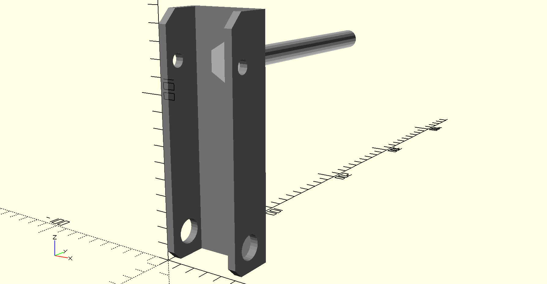
We need 2x 148mm lengths of 50mm x 5 SHS and we need 2x M12 x 140mm hex bolts. Later, when we get to assembling the trike, we'll also need 2x M12 nylok nuts and 4x M12 steel washers. While you're at the local hardware, get yourself a quality drill press and work vice, if you haven't already got one. I'm not kidding. You really need a milling machine with a precision vernier work table, but you can do this with a drill press, a proper one, not a drop-your-drill-in toy. You most certainly will screw this up if you try to hand drill it, no matter how well you measure and mark.
Now we have to drill 5x very precisely positioned holes, and we have to cut 20mm off the depth off the SHS, using an angle grinder. Optionally, we can also do a shallow chamfer from 30mm deep, at 124mm up (halfway) from the bottom, to 15mm deep at the top. It's also a good idea to chamfer or round the corners.
All the cutting aside, if you can't get the drilling right, you can't build this trike. Yeah, I'm writing this for me. 😂
Measurement & Drilling
Here's the 2D sketch with dimensions...

Do the drilling before cutting each bracket to open it up as a channel. As I say above, you need at least a sturdy drill press and work vice to clamp the SHS so that it's level and resting all the way into the vice. Mark and drill the half inch pivot hole at the bottom and drill it through from top side to bottom. Do a smaller pilot hole first, as this will be more accurate than starting at the full size. Then drill the smaller, 8mm tie rod mounting hole at the top, again pilot the hole first at the top and drill through both sides from the top with the bigger drill.
I'm using 1/2" UNC bolts for my kingpins because I have a 1/2" drill bit and the size of bolts I needed (M12x65) were out of stock at my local hardware. I do also have a 12mm drill bit, and could stay entirely metric. Readers in the USA may want to stay entirely Imperial. Either/or will work, provided you remember what you're using and remember an M8 flexible coupler needs a 5/16" pivot bolt, but really, don't mix and match. Do as I say, not what I've done. 😂
Next, we have the most critically accurate hole, the 12mm axle hole for the M12 x 140 through axle bolt. Both brackets require this hole to be exactly at the same height and equally forward offset, to as closely to sub-millimetre accurate as you can drill it. This is where the opposite hand construction begins, with the axle hole being 12 to 13mm off-centre towards the front of the bracket. This is equivalent to the trail offset of a bicycle, although, because of the centre pivot steering, not as much is needed.
Cutting & Welding
Make the cuts to the SHS to open it into a 50 x 30 channel. Then make the soft diagonal cut at the top. Next, chamfer (if you're lazy) or round the corners of the cuts.
Here's a quick tip. Grind out a 13mm slot in the fixed jaw of a large clamp. This will allow you to clamp around the shaft of the bolt with the screw jaw sitting on the bolt head.
Finally, insert the axle bolt in the axle hole, clamp it so the head sits perfectly flat. You may need to use your angle grinder to remove a little of the inner bevel inside the bracket, as well as at least some of one side of the bolt head, so that the bolt head can sit flat. Clamp and check the bolt is square to the outside face of the bracket, vertically and horizontally. Now weld the bolt to the bracket all the way around bolt head, running the weld up the sides of the bracket and across the top of the bolt head, if necessary.
Again, I can't stress enough how important accuracy is. This bolt has to protrude absolutely perpendicular to the outside face of each bracket. The 2 bolts in the 2 brackets must be completely coaxial to each other with the brackets back to back. The must have the same horizontal offset, and be the same height above the bottom pivot holes. Likewise for the tierod holes. If these brackets have any noticeable asymmetry to each other, the trike will have tiny, but potentially difficult handling issues, causing steering errors or imbalance, tyre wear or even instability in corners.
Measure twice, cut once. I'm reminding myself of this, too.
Handlbar Mounts
I haven't fully figured out how, yet, but this bracket will also be where the handlebar mounts. I want to do a standard, 31.8mm stem clamp thing on each of these tilt brackets, then cut a straight bar in half, so that they stick straight up. It'll probably be a 10 x 1.6 SHS post, coming out of the front-inside of the bracket, halfway up, then the bar clamp will be a piece of 35 x 1.6 EHS welded on a vertical axis, with two nuts welded to one side of a vertical cut-through and 2 nuts drilled out, welded to the other side, through which the M5 tightening bolts will pass. More info as I work on the bracket design. Remember, half a handlebar, clamped to each bracket, so there's a handlebar each side.