Branch Your Test Logic - campsych/concerto-platform GitHub Wiki
The order in which nodes in the flow chart are executed is defined by how the execution ports are connected. Execution always starts from the test start node but thereafter you can branch your logic however you want. Each of your nodes can have multiple execution out ports, or branches.
When a node has finished executing, the test logic of that node’s source test should determined which branch to go down, and thus which node to execute next. Only one branch can be selected and the flow will continue thereafter to whichever node is connected to that selected branch.
If your test is using more than a single branch, you needs to define a special return variable called .branch. The value of this variable should be set at test execution and it will determine which branch should be selected. In this scenario the execution flow will go through the branch with the same name as the value of the .branch return variable.
We’re going to create a node that will read two inputs: a and b and try to divide a by b, unless b is equal to zero. If b is zero, we will show a page saying that you cannot divide by zero. If it isn’t zero, we will show a page with the result.
- Create a node to perform our calculation
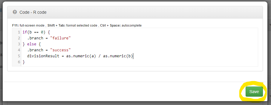
Add an eval node to your flowchart by right-clicking on your flow and selecting eval node.
Set its Code property to below.
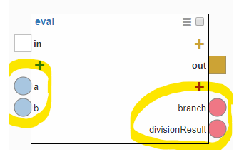
- Add input and return variables for Division node
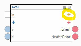
You need to add dynamic input nodes a and b and dynamic return nodes divisionResult and .branch that will be responsible for deciding the route for execution flow.
When done your node should look like this.
- Set the node’s possible branches
First we need to get rid of the default out branch. To do that click on its name.
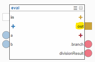
Then click Hide/Remove port button to hide it.
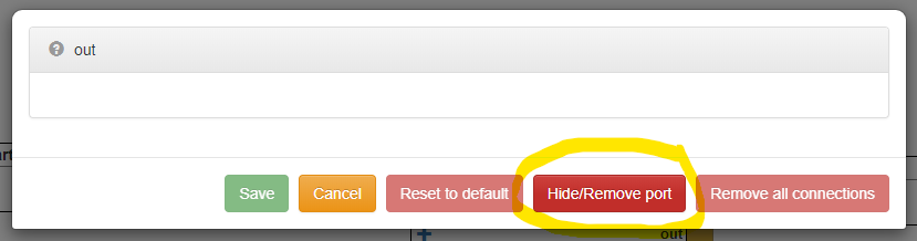
You will be prompted to confirm your action. Answer Yes to the prompt.
Now let’s add our custom branches. To add a new branch, click the yellow plus icon on the right side of the node.
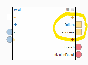
Add two dynamic branches: success and failure.
This is how your node should look when done.
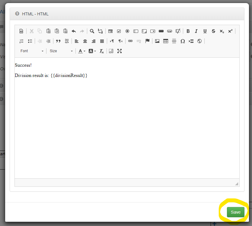
- Add page that we want to show to user when operation is a success
Add showPage node to your flow. Set its HTML property to:
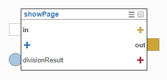
Add a dynamic input called divisionResult to your showPage node. Your node should now look like this.
- Add page that we want to show to user when operation is a failure
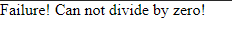
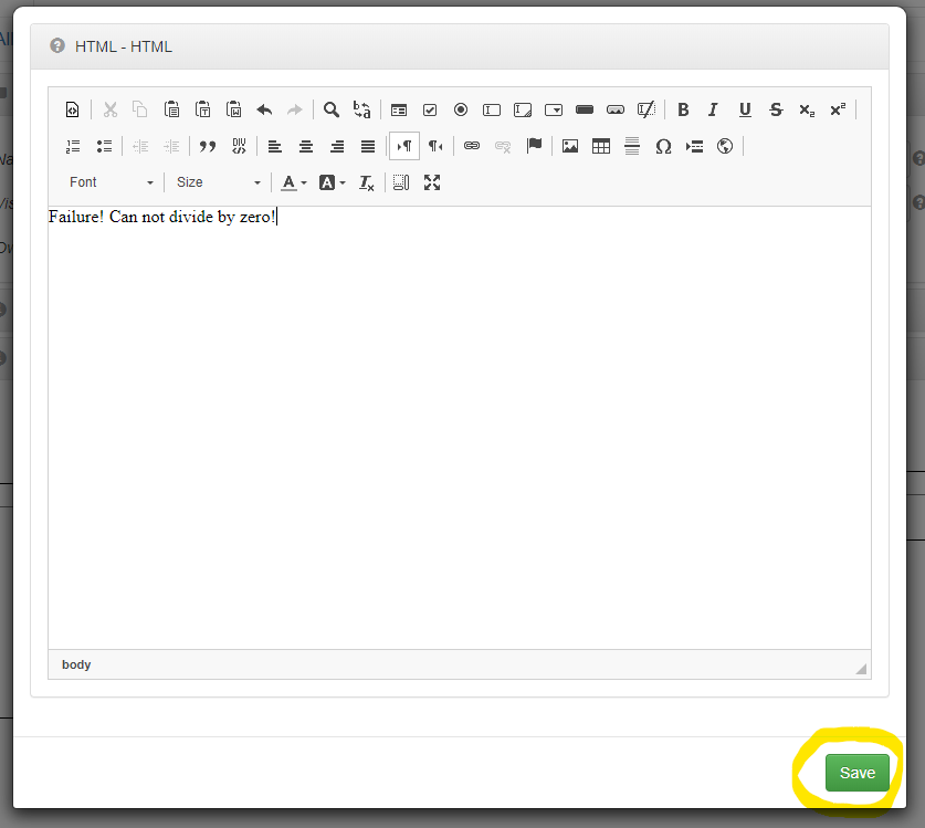
Add showPage node. Set its HTML property to:
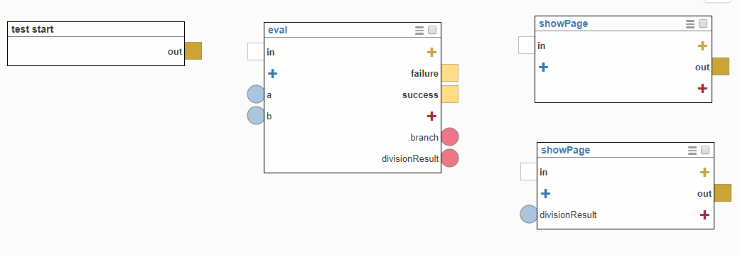
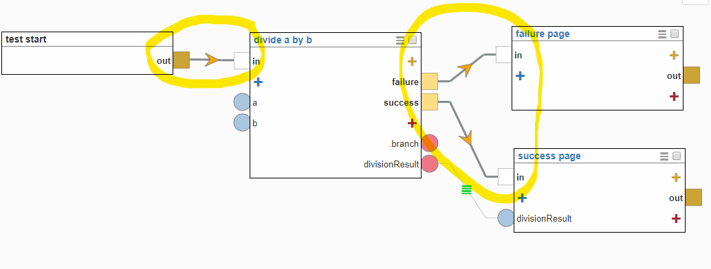
When done your flowchart should look like this:
- Make nodes more recognisable
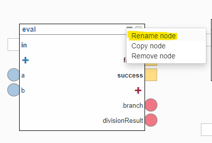
We already have two showPage nodes in our flow. This makes it hard to notice their purpose at first glance. Let’s rename all our nodes, so we know exactly what are they doing. To rename a node, right-click on it or click its actions icon.
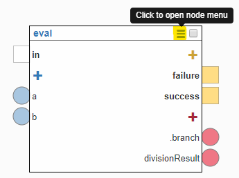
Then click Rename node.
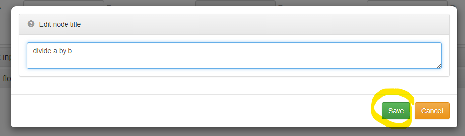
Let’s name our eval node: divide a by b and Save it.
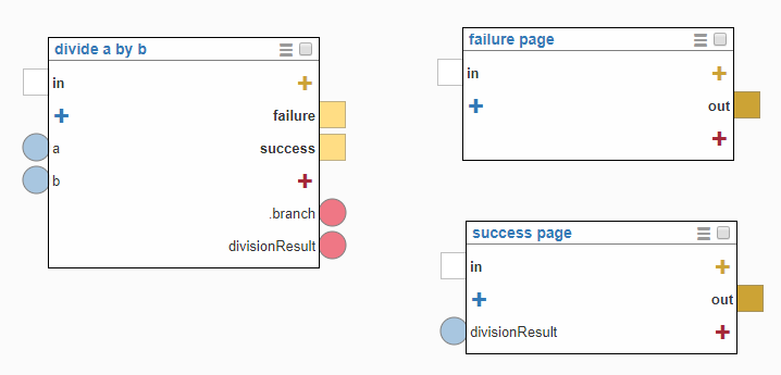
Now, let’s also rename our showPage nodes. Name one of them success page and the other failure page corresponding to their function. This is how our renamed nodes should look now.
- Data flow
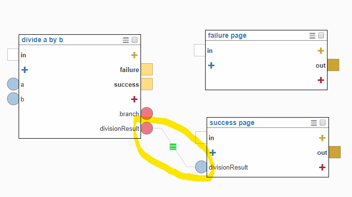
Now, let’s set our data flow. Connect the divisionResult dynamic return port from divide a by b node to the divisionResult dynamic input port on the success page node. This is done by clicking and dragging
- Execution flow
This is where our branches comes into play. We need to connect the success branch on the divide a by by node with our success page and the failure branch with our failure page. Don’t forget your execution needs to start from the test start node. Here’s how it should look now:
Well done! Now, let’s test it out.
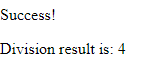
Let’s set a and b inputs first to 8 and 2 respectively. Click Run test and you should see that the success page is shown to the user as below:
Now, let’s change the value of b input to 0, so that the values of a and b are 8 and 0 respectively. This time the execution will go down the other branch and we’ll see the failure page as below: