Hardware Arilux AL LCxx - brusdev/espurna GitHub Wiki
Arilux AL-LCxx
| LC01 | LC02 | LC11 |
|---|---|---|
 |
 |
 |
| Property | Value |
|---|---|
| Manufacturer | Arilux |
| Product page | |
| Wiki page | |
| Build flag | ARILUX_AL_LC01ARILUX_AL_LC02 ARILUX_AL_LC11 |
Introduction
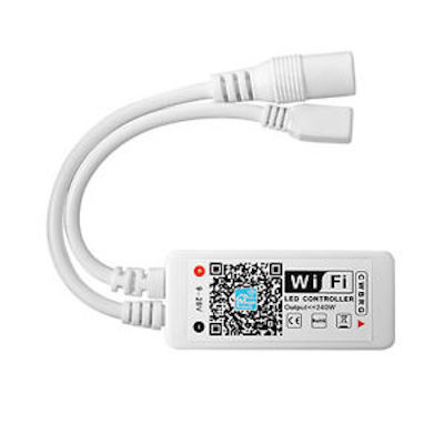
| LC01 | LC02 | LC11 |
|---|---|---|
| Working Voltage: DC 5-28VOutput Channel: 3 channelsOutput Current: RGB, 4Ax3Max. Power: 4A x 3 x 12V = 144WConnection: Common anodeDimension: about L46 x W19 x H8 mm | Working Voltage: DC 9-12VOutput Channel: 4 channelsOutput Current: RGBW, 4Ax4Max. Power: 4A x 4 x 12V = 192WConnection: Common anodeDimension: about L46 x W19 x H8 mm | Working Voltage: DC 9-28VOutput Channel: 5 channelsOutput Current: RGBW/WW, 4Ax5Output Power: ≤240WConnection: Common anodeDimension: about L46 x W19 x H8 mm |
Flashing
Open the plastic enclosure (using a sharp tool) and extract the little board inside.
You will see some soldering points with labels: GND, TX, RX and I00. If you are good enought with the soldering iron, connect dupont wires to these pads (check this guide).
If you prefer to got the safe way, use this tricky method:
- bend the tip of some dupont wires
- glue the tip to a short piece of a ziptie
- hold the board in place with a couple of pins,
- hold the the zipties with clothespins
- adjust the tips of the dupont wires placing them carefully on the soldering pads


Finally, connect the dupont wires to your FTDI-USB dongle:
- TX -> RX
- RX -> TX
- GND and I00 -> GND
And follow the general instructions in this page to start the flashing procedure.
Issues
TODO