Reading From a Photoresistor - borq79/cs.edu GitHub Wiki
Examples using an Photoresistors and LEDs
Note, all parts used in the examples (except the photoresistor and photoresistor module) are available in the Vilros Ultimate Starter Kit
In the following examples you will learn how to read a simple photoresistor and a photoresistor that is part of an integrated PCB module. These examples will drive LEDs. To see more about how to just work with the LEDs, please review
Before starting, it helps to understand the two different types of ways to drive the output pins on the Arduino.
Digital Write
The easiest of the two is using the built in function digitalWrite(). The digitalWrite() function takes in two values, the pin number and the value (HIGH or LOW). The digitalWrite() value is discrete and must be either HIGH (5V) or low (0V). This is useful if you simply wish to control if the LED is on or off (like in the blink example).
Analog Write
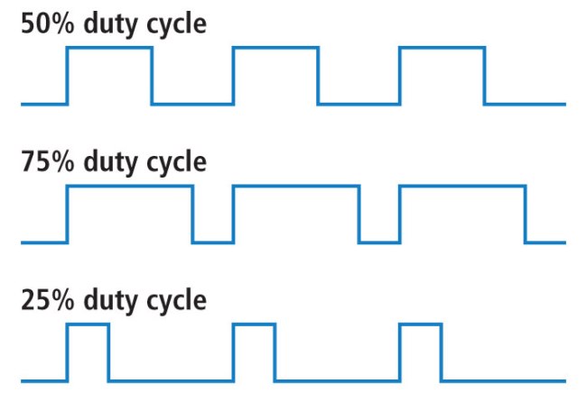
Turning the LED on and off is useful, however, if you wish to adjust the brightness of the LED you will need to use the analogWrite() function. The Arduino analogWrite() doesn't actually output an analog value but emulates an analog signal by configuring the pin as a PWM (Pulse Width Modulation). The analogWrite() function also takes two values, the pin number and the 'analog' value (0-255). 0 Means the pin will output a wave form with a 0% duty cycle (or basically 0V). As you increase the number towards 255 the duty cycle increases towards 100% (effectively 5V). The following diagram illustrates how the duty cycle of the output changes the wave form.
According to the documentation of analogWrite(), 'The PWM outputs generated on pins 5 and 6 will have higher-than-expected duty cycles. This is because of interactions with the millis() and delay() functions, which share the same internal timer used to generate those PWM outputs. This will be noticed mostly on low duty-cycle settings (e.g 0 - 10) and may result in a value of 0 not fully turning off the output on pins 5 and 6.'
Photoresistor
A photoresistor is an electrical component that increases or decreases its resistance based upon how much light is hitting the photosensitive component. As the light that hits it increases, the resistance decreases. So when it is bright, the resistance is low (allows more current to pass through). When it is dark, the resistance is high (allows less current to pass through). This page provides a bit more information on the photoresistor and how you can build a simple circuit (without an Arduino) to see how it works.
Voltage Division
Before you can really understand how the example circuits work, it is best to understand how to determine the resistance of the photoresistor. The Arduino doesn't have a pin that allows you to plug it in and measure the resistance or current. What it does have is a way to measure voltage via the Analog input pins (A0 - A5). How you build a circuit that will allow the Arduino to read a change in voltage? The answer comes from the understanding of Ohm's Law and how voltage is changed in a series circuit when resistance is changed. More specifically, you need to build a voltage divider so that you can measure the change in voltage across the photoresistor.
A voltage divider circuit looks as follows (from Wikipedia):

For the Arduino, we are interested in the Vout value in reference to Ground. This is where we will attach the A0 pin to in all the circuits below.
If you leave Vin constant (5V) and R1 stays the same (e.g. 100 Ohms), but R2's value changes (e.g. the photoresistor) then Vout will also change. To understand the change of Vout, we need to know the voltage division function (from Wikipedia):
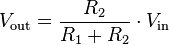
If we plot out this function given Vin is 5V and R1 is 100 ohms, Vout will change as follows:

Simple Circuit - Reflect the Intensity of Light via an LED
This example will drive an LED via the PWM to reflect the voltage across the photoresistor.
Parts List
- Arudino Uno (any Rev should be fine, but diagrams are based on Rev 3)
- Breadboard
- USB Cable
- Arduino Software installed on a Mac or PC
- 1 10K Ohm resistor
- 1 330 Ohm resistor
- 1 LED
- 5 Wires
- 1 GM5539 5539 Photoresistor
Wiring the Circuit
This schematic shows you how to wire up the Arduino. Make sure to note the orientation of the Arduino in relation to the Breadboard. Also note that the Anode (positive) leg/post/pin of the LED is the longer leg/post/pin of the LED. Sometimes there is a flat side to the LED which helps denote the cathode (negative) leg/post/pin of the LED. You always want to attach the anode (positive) leg/post/pin of the LED to the power rail (5V) and the cathode to ground (GND). In all scenarios you will want to place a resistor (the 1K) in series with the LED to avoid damaging the LED and/or Arduino. The larger resistor you use the dimmer the LED will be. You can experiment with different resistor values and see how they change the LED brightness. In this example, use the 10K resistor in series with the photoresistor.
Programming the Arduino
The following code is what you use to drive this circuit: Photoresistor Example
Build a Light Monitor out of an LED array
This example is an amplified version of the previous example. Rather than drive just one LED, this example will drive a series of 5 LEDs. The LEDs are each attached to a different PWM so that as the light gets brighter we can vary the brightness of the LEDs. When the room is totally dark all 5 LEDs will be off. As the light increases the first LED will begin to get brighter until is 100%, then the second LED will start to increase, etc. until all 5 LEDs are bright. Since the input range is 0 - 1023 we have to divide the values up into 5 ranges. Each LED will have one of the smaller ranges assigned to it.
Parts List
- Arudino Uno (any Rev should be fine, but diagrams are based on Rev 3)
- Breadboard
- USB Cable
- Arduino Software installed on a Mac or PC
- 1 10K Ohm resistor
- 5 330 Ohm resistors
- 5 LEDs
- 9 Wires
- 1 GM5539 5539 Photoresistor
Wiring The Circuit
This schematic shows you how to wire up the LEDs and Photoresistor using a breadboard and the Arduino. Make sure to note the orientation of the Arduino in relation to the Breadboard. Similar to the circuit in the previous example you will want to place a resistor in series with all the LEDs so they are not damaged. In this example, use the 10K resistor in series with the photoresistor.
Programming the Arduino
The following code is what you use to drive this circuit: Photoresistor LED Array Example
Using a Photoresistor Module
If you want to make more of a 'trip sensor' or a 'light sensor' setup you can invest in one or two photoresistor modules that allow you to either read an analog output of the light resistance or a digital output that indicates if the room is either bright or dark. You are able to adjust the threshold for bright and dark with the screw on the top of the module. When the module is combined with a strong laser diode it can be used as a 'trip sensor'. If the beam is directed at the photoresistor then anytime the beam is interrupted the photoresistor will increase in resistance and this can be detected on either the analog or digital pin. This same setup can be done with just the photoresistor (and no module) but the digital output makes this much easier.
In some of the examples, the 'module' version is referenced. In those scenarios, this part is used