Examples using an LED - borq79/cs.edu GitHub Wiki
Examples using an LED
In the following examples you will learn how to drive an LED, blink and LED, and increase and decrease the brightness of the LED.
Before starting, it helps to understand the two different types of ways to drive the output pins on the Arduino.
Digital Write
The easiest of the two is using the built in function digitalWrite(). The digitalWrite() function takes in two values, the pin number and the value (HIGH or LOW). The digitalWrite() value is discrete and must be either HIGH (5V) or low (0V). This is useful if you simply wish to control if the LED is on or off (like in the blink example).
Analog Write
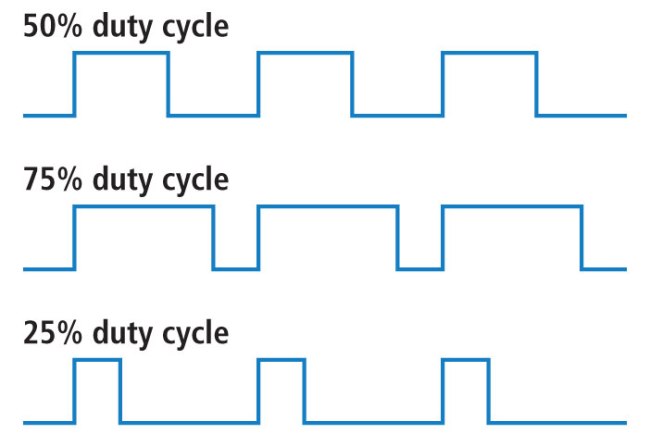
Turning the LED on and off is useful, however, if you wish to adjust the brightness of the LED you will need to use the analogWrite() function. The Arduino analogWrite() doesn't actually output an analog value but emulates an analog signal by configuring the pin as a PWM (Pulse Width Modulation). The analogWrite() function also takes two values, the pin number and the 'analog' value (0-255). 0 Means the pin will output a wave form with a 0% duty cycle (or basically 0V). As you increase the number towards 255 the duty cycle increases towards 100% (effectively 5V). The following diagram illustrates how the duty cycle of the output changes the wave form.
According to the documentation of analogWrite(), 'The PWM outputs generated on pins 5 and 6 will have higher-than-expected duty cycles. This is because of interactions with the millis() and delay() functions, which share the same internal timer used to generate those PWM outputs. This will be noticed mostly on low duty-cycle settings (e.g 0 - 10) and may result in a value of 0 not fully turning off the output on pins 5 and 6.'
Simple Circuit - Drive an LED
This example is about as simple as you can get for the Arduino. You don't even need to write a program! You can just use the 5V Rail and the Ground (GND) pins for the LED.
Wiring the Circuit
This schematic shows you how to wire up the Arduino. Make sure to note the orientation of the Arduino in relation to the Breadboard. Also note that the Anode (positive) leg/post/pin of the LED is the longer leg/post/pin of the LED. Sometimes there is a flat side to the LED which helps denote the cathode (negative) leg/post/pin of the LED. You always want to attach the anode (positive) leg/post/pin of the LED to the power rail (5V) and the cathode to ground (GND). In all scenarios you will want to place a resistor in series with the LED to avoid damaging the LED and/or Arduino. The larger resistor you use the dimmer the LED will be. You can experiment with different resistor values and see how they change the LED brightness.
These photos show an actual Arduino wired up for additional details on where the LED and resistor is placed. In these two examples you can see that the LED in the first image is much brighter. That is because the resistor value is lower than in the second photo below, where the resistance is much higher.
Lower Resistor Value https://github.com/borq79/cs.edu/blob/master/projects/arduino/leds/images/basic_led_wiring_photo_lower_resistence.jpg
Higher Resistor Value https://github.com/borq79/cs.edu/blob/master/projects/arduino/leds/images/basic_led_wiring_photo_higher_resistence.jpg
Blink an LED at a Constant Rate
If you want to do something other than just turn the LED on when the Arduino has power, you will need to wire the circuit up a little different. This time you will use one of the digital pins as an output (remember the Arduino can configure some pins as input or output). When the LED anode post is wired to the digital output pin of the Arduino you can then control when the LED is on (pin is driven HIGH) and when the LED is off (pin is driven LOW).
Wiring The Circuit
This schematic shows you how to wire up the LED using a breadboard and the Arduino. Make sure to note the orientation of the Arduino in relation to the Breadboard. Similar to the circuit in the previous example you will want to place a resistor in series with the LED.
This photo shows an actual Arduino wired up for additional details on where the LED and resistor is placed.
Wiring Photo https://github.com/borq79/cs.edu/blob/master/projects/arduino/leds/images/simple_blink_led_wiring_photo.jpg
Wiring Photo - Up Close https://github.com/borq79/cs.edu/blob/master/projects/arduino/leds/images/simple_blink_led_wiring_up_close_photo.jpg
Programming the Arduino
After you have the circuit wired up according to the diagrams above, you can load the following sketch, which will drive pin #3 HIGH and LOW with a one second delay between each write to blink the LED.
Simple LED Blink Arduino Sketch
Slow fading of an LED Using the PWM
Leaving the LED wired up the same as it was for the blinking example (previous example), you only need to load the following sketch to drive pin #3 as a PWM. The program will adjust the duty cycle of the PWM over the course of 10 seconds (higher for 5 seconds and then lower). By adjusting the PWM duty cycle the LED will adjust in brightness accordingly.