Unit 1 Boolean Functions and Gate Logic - birdybro/Nand2Tetris_MiSTer GitHub Wiki
Module 1 (I thought it was called unit 1??)
intro to boolean algebra (uhoh), learn how boolean functions can be implemented using logic gates, then how to specify gates and chips using HDL, and how to simulate the behavior using a hw sim, all for some background on how do things.
This is all in text so far, I had to add files to the course_files/Week 1 folder that I may need to reference. These are excerpts from their book apparently (the course is free and open source I believe, might be kosher to do it here, i dunno, guess we'll find out?) They say I should read these documents, then say I don't need to read them back to back, so confusing lol... Why do I get hung up on this stuff though, move forward plz.
Filenames must exactly match the nand2tetris/projects/01 folder's names. filenames are case-sensitive for testing and grading, so get that part right!!!
Unit 1.1: Boolean Logic
Boolean values can be:
False or True
No or Yes
0 or 1
We'll use 0 and 1 cuz it's better.
Boolean operation examples
First example is the AND operation!
(x AND y) or x (he has like a triangle/arrow with only 2 sides pointing up for some reason sorta like ^) y
| x | y | AND |
|---|---|---|
| 0 | 0 | 0 |
| 0 | 1 | 0 |
| 1 | 0 | 0 |
| 1 | 1 | 1 |
So AND only returns 1 if both values are 1. kewlio -
Next is the OR operation (if any one of the inputs are true, then it's true, only time it's false is if both are false):
| x | y | OR |
|---|---|---|
| 0 | 0 | 0 |
| 0 | 1 | 1 |
| 1 | 0 | 1 |
| 1 | 1 | 1 |
Next si the NOT operation NOT(x)
| x | NOT |
|---|---|
| 0 | 1 |
| 1 | 0 |
So like ~ in verilog/systemverilog, but NOT in VHDL. kewehll
Boolean Expression examples
Boolean expressions are combinations of boolean operations (e.g. NOT(0 OR(1 AND1))=). He asks to evaluate it, 1 and 1 is 1, 0 or 1 is 1, not 1 is 0. The answer to NOT(0 OR(1 AND1))= is 0 (I think), see if I'm right... I was right!!! :D
quiz is 1 AND (0 OR (NOT (1))) next... The answer to this is... Not 1 = 0, 0 or 0 = 0, 1 AND 0 = 0. The answer should be 0! CORRECT you will be assimilated hooman. Nice!
Boolean Function examples
f(x, y, z) = (x AND y) OR (NOT(x) AND z)
Use x y and z as inputs, if i feed a 1 or 0 into any of these, it will change the result. I'll calculate all of these to try and get some repetition learning in:
| x | y | z | f |
|---|---|---|---|
| 0 | 0 | 0 | 0 |
| 0 | 0 | 1 | 1 |
| 0 | 1 | 0 | 0 |
| 0 | 1 | 1 | 1 |
| 1 | 0 | 0 | 0 |
| 1 | 0 | 1 | 0 |
| 1 | 1 | 0 | 1 |
| 1 | 1 | 1 | 1 |
I think this is right, let's see the result...
I GOT IT RIGHT!! :)
Boolean Identities
commutative laws examples:
- (x AND y) = (y AND x)
- (x OR y) = (y OR x)
associative law examples:
- (x AND (y AND z)) = ((x AND y) AND z)
- (x OR (y OR z)) = ((x OR y) OR z)
distributive law examples:
- (x AND (y OR z)) = (x AND y) OR (x AND z)
- (x OR (y AND z)) = (x OR y) AND (x OR z)
De Morgan law examples (this one confuses me a little, but i got it after a sec):
- NOT(x AND y) = NOT(x) OR NOT(y)
- NOT(x OR y) = NOT(x) AND NOT(y)
They quizzed me on what the results should be to prove De Morgan's Law, and I passed, correct on both answers :)
Boolean Algebra
NOT(NOT(x) AND NOT(x OR y))
Apply De Morgan's law and:
NOT(NOT(x) AND (NOT(x) AND NOT(y)))
Apply associative law:
NOT((NOT(x) AND NOT(x)) AND NOT(y))
the phrase NOT(x) AND NOT(x) can be simplified to just NOT(x) because like 1 AND 1 is the only way to get 1 and the only way to get that is NOT(0) which x are the same, so if x is ever 0 then this will always be 1, so it's the same thing. He explains it some other academic'y way that I don't find easy to understand. It's called the law of idempotence though or something so we'll do that below:
NOT(NOT(x) AND NOT(y))
Apply De Morgan's Law again:
NOT(NOT(x)) OR NOT(NOT(y))
Apply double negation law (don't know what that is but lol he's saying it, thought this was a no pre-reqs course damnit!!):
x OR y (wtf)
Unit 1.2 - Boolean Functions Synthesis
Let's take the truth table from last time but have different outputs from the same inputs:
| x | y | z | f |
|---|---|---|---|
| 0 | 0 | 0 | 1 |
| 0 | 0 | 1 | 0 |
| 0 | 1 | 0 | 1 |
| 0 | 1 | 1 | 0 |
| 1 | 0 | 0 | 1 |
| 1 | 0 | 1 | 0 |
| 1 | 1 | 0 | 0 |
| 1 | 1 | 1 | 0 |
He's going to show me how to make a function for this by looking at the truth table?! awesome! He said this would be a disjunctive normal form for it lol
Go row by row on the truth table. Focus on the rows that have a value of 1. Then write an expression that gets the value of 1 only at that row that gets them, like this (I will try to do all of them before he presents the answer for exercise):
| x | y | z | f | Boolean Expression |
|---|---|---|---|---|
| 0 | 0 | 0 | 1 | (NOT(x) AND NOT(y) AND NOT(z)) |
| 0 | 0 | 1 | 0 | |
| 0 | 1 | 0 | 1 | (NOT(x) AND y AND NOT(z)) |
| 0 | 1 | 1 | 0 | |
| 1 | 0 | 0 | 1 | (x AND NOT(y) AND NOT(z)) |
| 1 | 0 | 1 | 0 | |
| 1 | 1 | 0 | 0 | |
| 1 | 1 | 1 | 0 |
And I got the same answers he laid out when I unpaused the vid, so yippee! Now to do the rest...
So the way you get a full boolean function that always returns 1 at these 3 locations on the truth table... is EASY. You just OR the boolean expressions together (and then obviously clean them up by applying the laws like earlier I guess?)!
(NOT(x) AND NOT(y) AND NOT(z)) OR (NOT(x) AND y AND NOT(z)) OR (x AND NOT(y) AND NOT(z))
They quizzed me on the 2nd entry in the table having an outcome of 1. Well that was ez it's (NOT(x) AND NOT(y) AND z)
Next he shows how to break it down, for some reason he skips a step and just turns it into:
(NOT(x) AND NOT(z)) OR (x AND NOT(y) AND NOT(z))
He just kinda did it and said you could write it that way, but I want to know why and how he did that... Oh I see, he saw that two of the expressions had (NOT(x) AND NOT(z)), so you just need to account for that combination and have an OR for the rest of what is going on.
(NOT(x) AND NOT(z)) OR (x AND NOT(y) AND NOT(z))
this is because in the first two boolean expressions it apparently doesn't matter what y is when you look at it. you get 1 regardless of what 1 is, only x and z matter, but just for those 2 outcomes.
Anyways, any boolean function can be represented with only AND and NOT operations, you can get rid of OR. This is due to De Morgan's Law, super cool.
NAND function
So there is one function that can do all this combined, it's called the NAND function.
| x | y | NAND |
|---|---|---|
| 0 | 0 | 1 |
| 0 | 1 | 1 |
| 1 | 0 | 1 |
| 1 | 1 | 0 |
(x NAND y) = NOT(x AND y)
The quiz asked me what is the negation of NAND(x,x) but the syntax is super confusing. The answer was NOT(x) but I don't really know why and the build up to it didn't make sense. Normally that is like an array or something, but this isn't code, so there must be some pre-requisite knowledge here that's missing.
Any boolean function can be represented with just NAND operations (amazin').
NOT(x)=(x NAND x)(okay this is whatNAND(x,x)is I think. Noted)(x AND y)=NOT(x NAND y)and I think this equals...((x NAND x) NAND (y NAND y))to get rid of the NOT operation.
Unit 1.3 - Logic Gates
Logic gates:
- elementary (NAND, AND, OR, Not, etc...) simple individual gates
- composite (Mux, Adder, etc...) made up multiple elementary logic gates
Nand gate diagram:
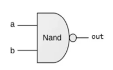
functional spec of a nand gate in pseudo code i guess:
if (a==1 and b==1) then out=0 else out=1
NAND gate truth table (already did this earlier, but repetition is key):
| x | y | NAND |
|---|---|---|
| 0 | 0 | 1 |
| 0 | 1 | 1 |
| 1 | 0 | 1 |
| 1 | 1 | 0 |
the NAND gate's truth table is the inverse of the OR gate's truth table, interesting.
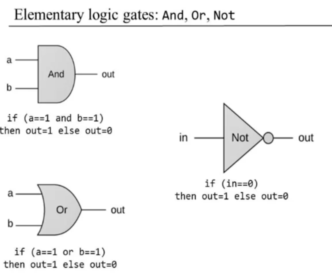
elementary logic gates diagrams and functional spec:
composite gates examples:
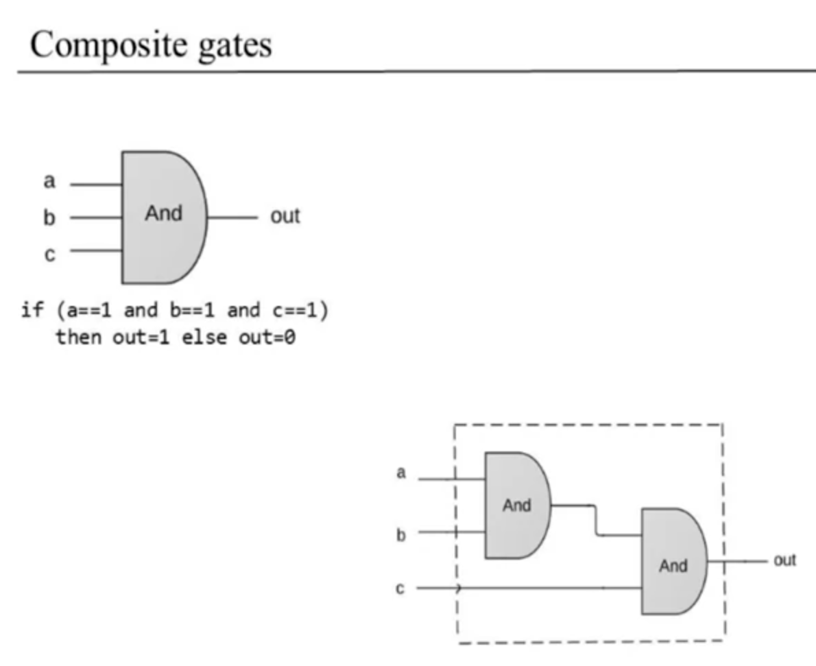
note: the order of the input bits in this composite logic gate does not matter, due to the associative law (i had to go look that up again since it was interesting) :)
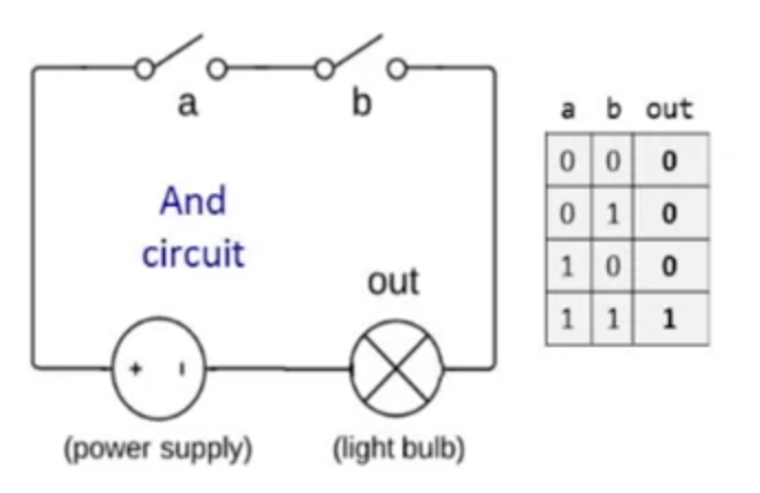
circuit implementations:
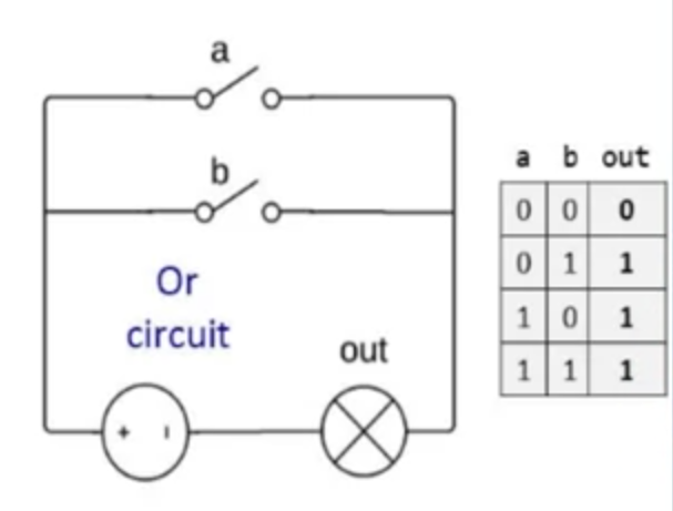
you can make these logic gates using physical hardware circuits, like with a lightbulb turning on with two light switches. this is a good analogy he's drawing:
AND gate physical circuit:
OR gate physical circuit:
Unit 1.4 - Hardware Description Language
I know that one!! (sorta)
He goes over an xor gate, introduces the concept of HDL which makes sense to me, shows a vague verilog'y pseudocode example of an xor gate to differentiate the input and output ports, the declaration of the module, and there is a "parts" section which would be the description of the logic in verilog i believe.
He says instead of first trying to build the xor gate, assume we already have an and gate, not gate, and or gate, and build the xor gate from those existing components. you first look at the truth table, come up with the rules for it, then come up with a gate logic diagram. I really am going to download a program that lets me plot these out so i can do extra repetition since that helps me learn, the diagram stuff would help me a lot.
I landed on this for now --> https://github.com/tallsop/BoolGate (edit: doesn't work for shit, i'll just ignore this now, i'm getting distracted) - since it's cute and simple, we'll see how that goes, i only need to focus on using these basic elementary gates so i think it will be fine.
He gave a diagram example with related HDL code like this:
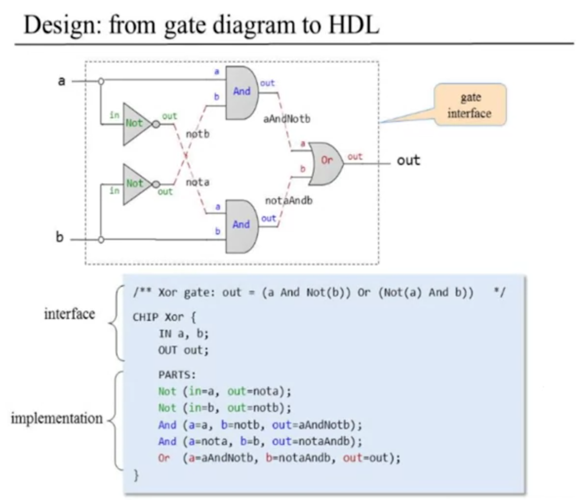
He will put out stub files and we have to add the code. for each of these files we look at the description, describe the diagram one chip part at a time.
Hopefully this HDL he showed isn't some new syntax for an imaginary HDL I have to learn LMAO, that would be annoying. Anyways, I should do it regardless, will be a useful exercise anyways.
What is this HDL syntax???
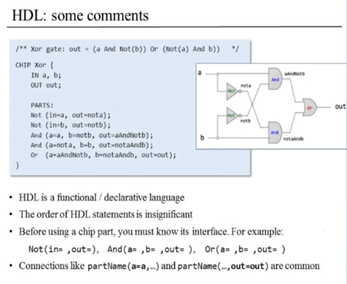
Super bizarre.
Still no project assigned, but this is a lot of stuff to take in and absorb so that's okay. The HDL is one that they made to be minimal and simple like verilog, but has a lot less syntax and special words to worry about, it's made for gates only it seems. No complex behavioral syntax to call to infer complex higher level stuff later.
Textbook Appendix A has the reference to all their HDL. Will probably need it for an exercise soon.
Unit 1.5 - Hardware Simulation
Hardware sim in a nutshell, load HDL into hw simulator, test the operations on that chip interactively. also you can write a test script to test operations on that chip in a script-based method. Also you can record output of the simulation into a file, and you can compare the output of the various simulation results of your circuit with another program they made.
He goes over the hw simulator, the interactive simulation can be too tedious, script based testing is preferable once you get to larger and complex circuits.
side note: Their hw simulator keeps crashing for me, it's broken in windows. i am also getting triggered just by reading their custom HDL syntax lol, i already know a decent amount of verilog syntax and consider it easy, i might just do it my own way and use it as an excuse to learn model sim or do some simpler simulation. or maybe i do repetition by rewriting all i do in both their weird hdl and in my own. also going to try and use wsl2+ubuntu now for loading the hw simulator since it's basically broken in windows 11. anyways... I might just do this in verilog and use the nand2tetris as a reference to the steps and the general concepts, i don't think i truly need to be using all of their hardware all along, but i do want to submit the projects and get the certificate since that would be cool. i dunno... ah well, i'll figure it out as i go along!!
He's kind of describing the general concepts of methods to make a design, not super specific important stuff, just giving you an idea of how the process goes at a company or something like that. Kind of a cool overview personally, I never looked at it this way before:
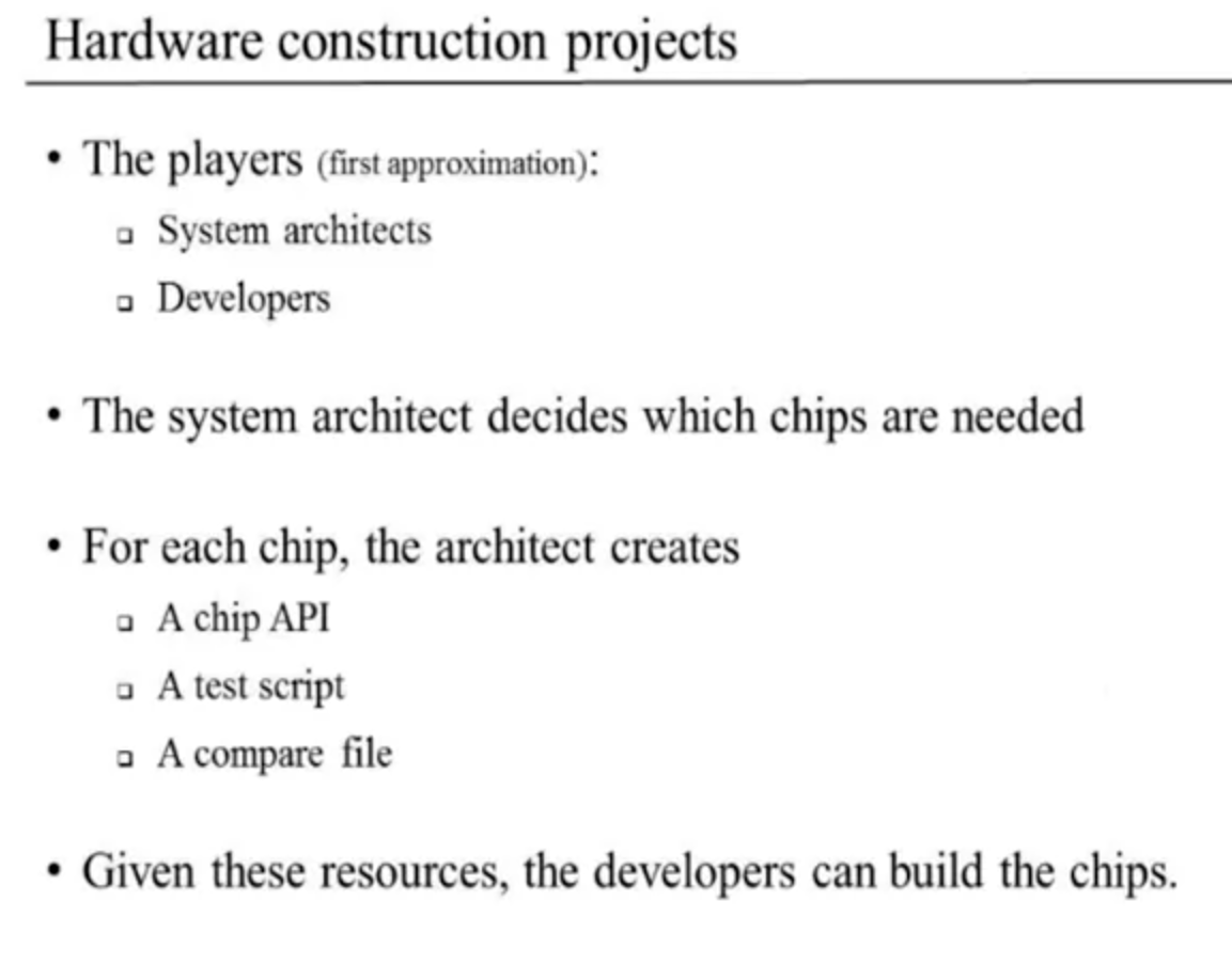
He says that he and the other course instructors play the role of the system architect in this analogy.
No quizzes this time, kind of an overview of the workflow i guess for simulation which wasn't too critical or bad, seems like a very intuitive process. I never usually have problems understanding the tools.
Unit 1.6 - Multi-Bit Buses
Arrays of Bits
- Sometimes we manipulate "together" an array of bits.
- It is conceptually convenient to think about such a group of bits as a single entity, sometimes termed "bus".
- HDLs will usually provide some convenient notation for handling these buses.
Example:
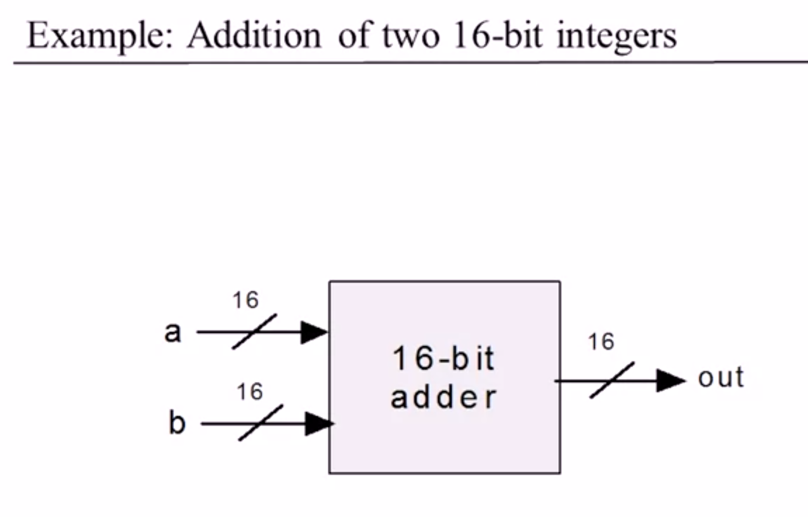
This has 32 wires feeding into it and 16 out, but it's more convenient to think of it as having 2 values feeding in and 1 value feeding out.
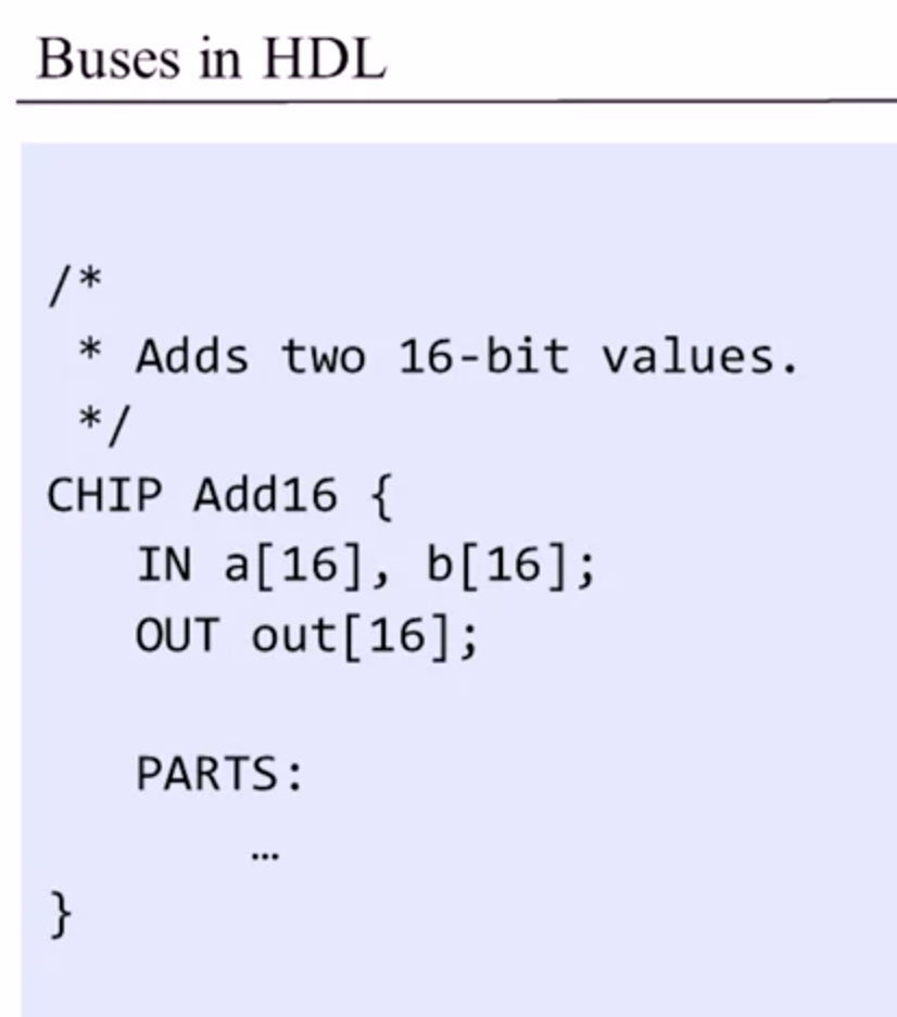
Example of their version of HDL describing that chip:
Example of adding 3 16-bit values using their HDL type:
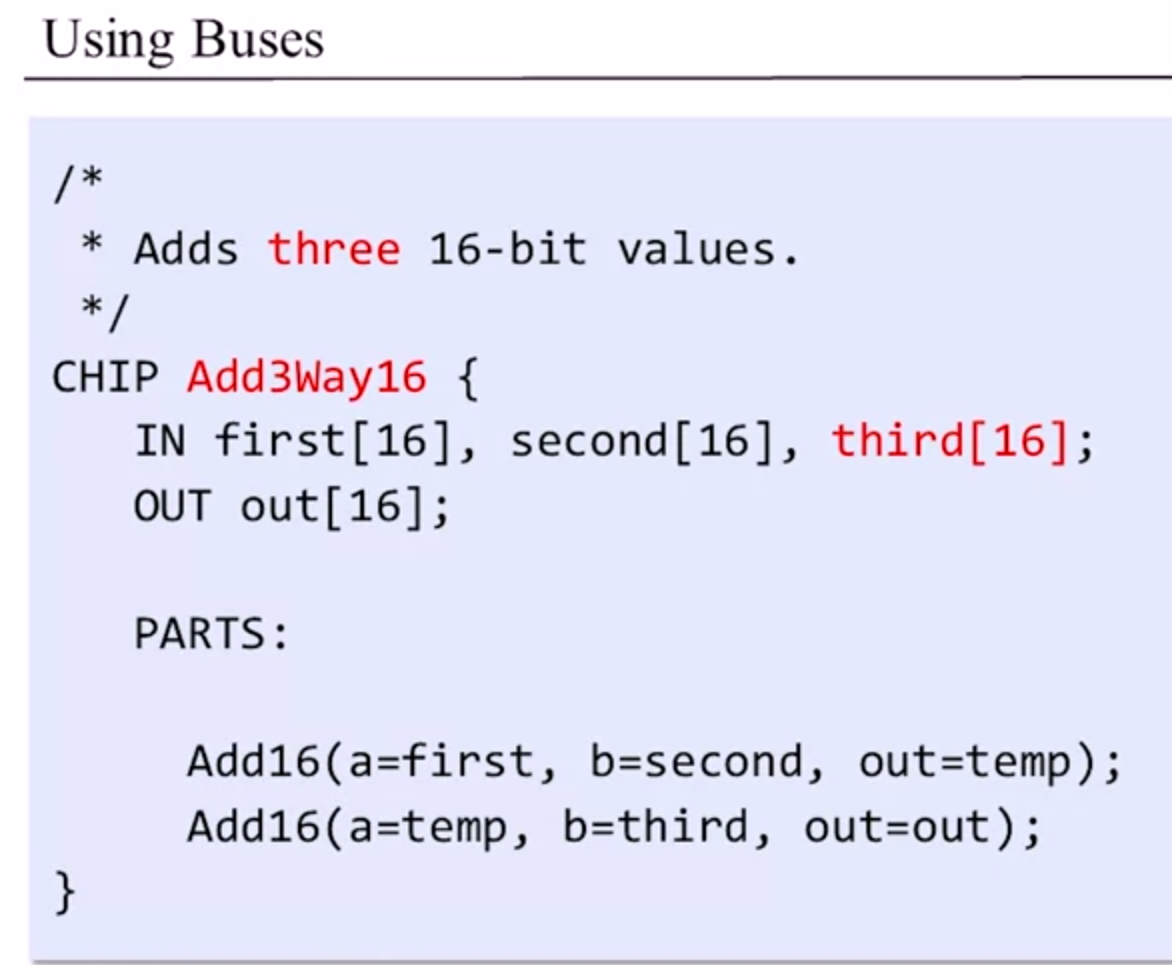
Asked me a syntax question for their HDL, pretty easy, was about how bits go from 15 downto 0 (or in this case 0 upto 15) for a 16-bit bus representation.
Another example of working with buses:
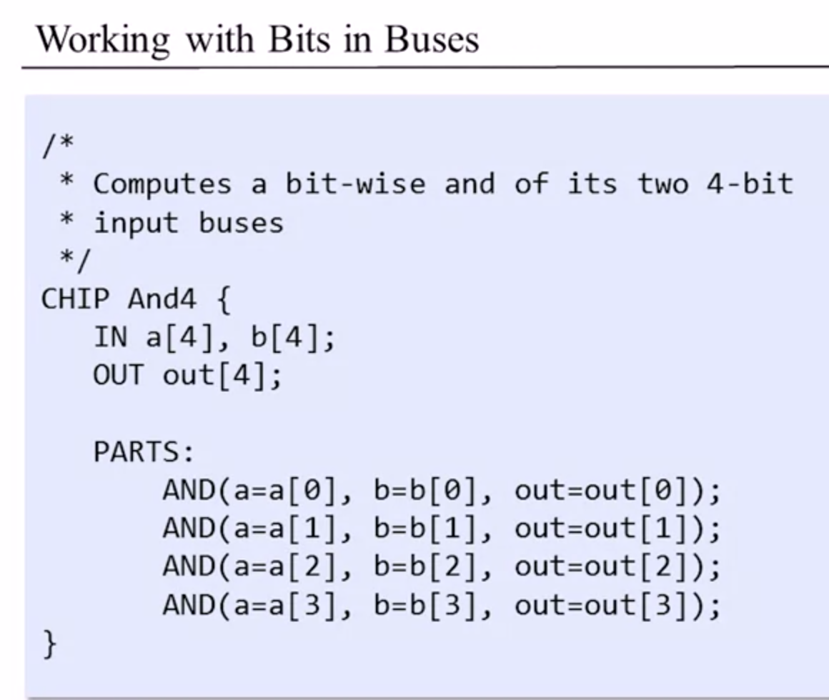
The question they asked was a bit confusing, but I think I get it. I think it's because I'm used to the languages VHDL and Verilog currently so their language trips me up a bit for some of the address handling.
Unit 1.7 - Project 1 Overview
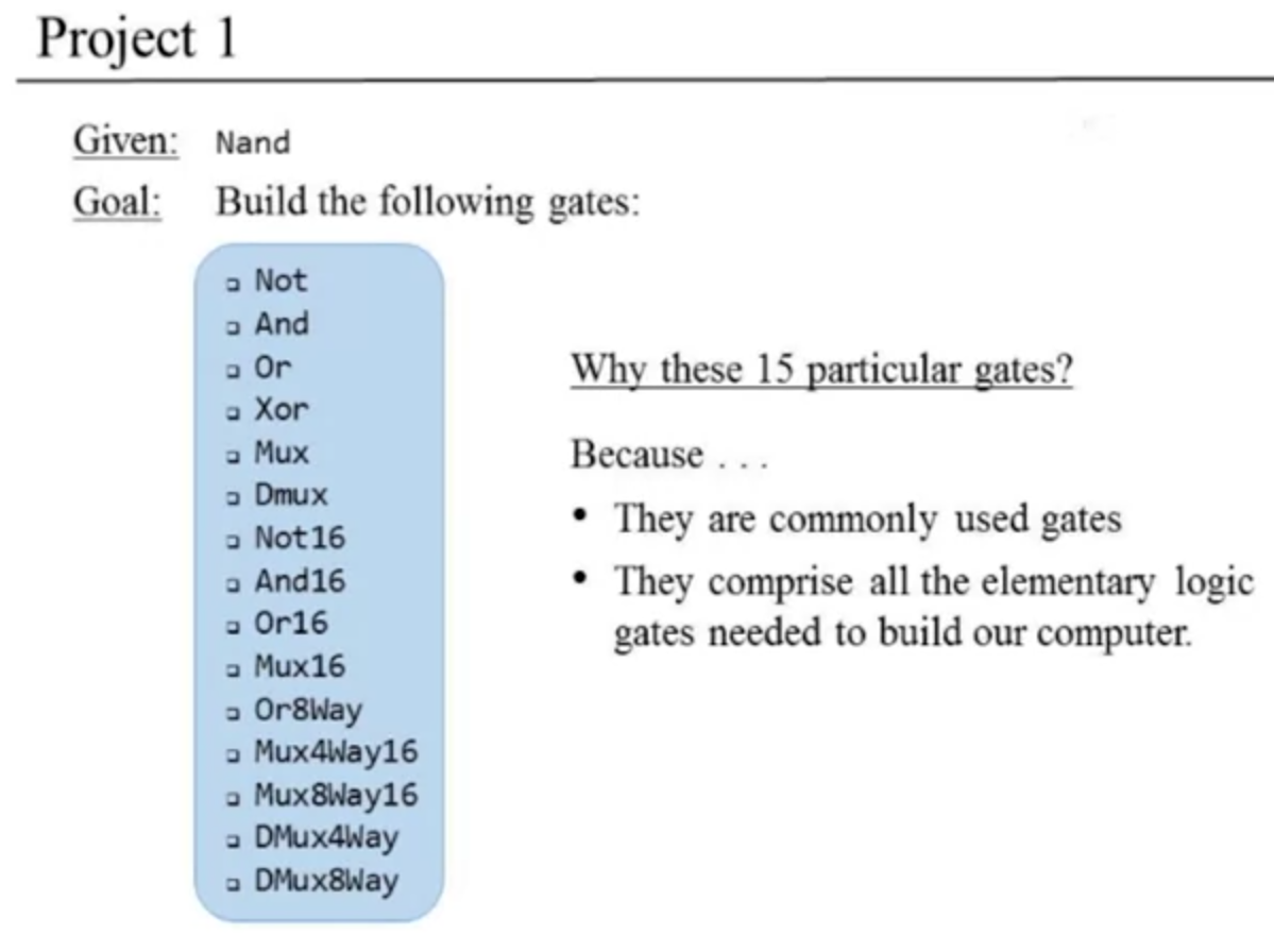
Seems simple enough... I hope???!?!
Categorized view of the chips we will build from a sec ago:
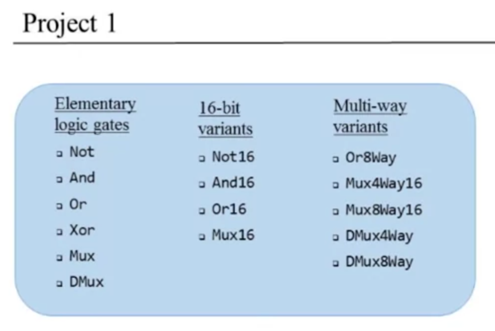
He will focus so far on just the Mux, DMux, And16, and Mux4Way16 currently to show us how to do it.
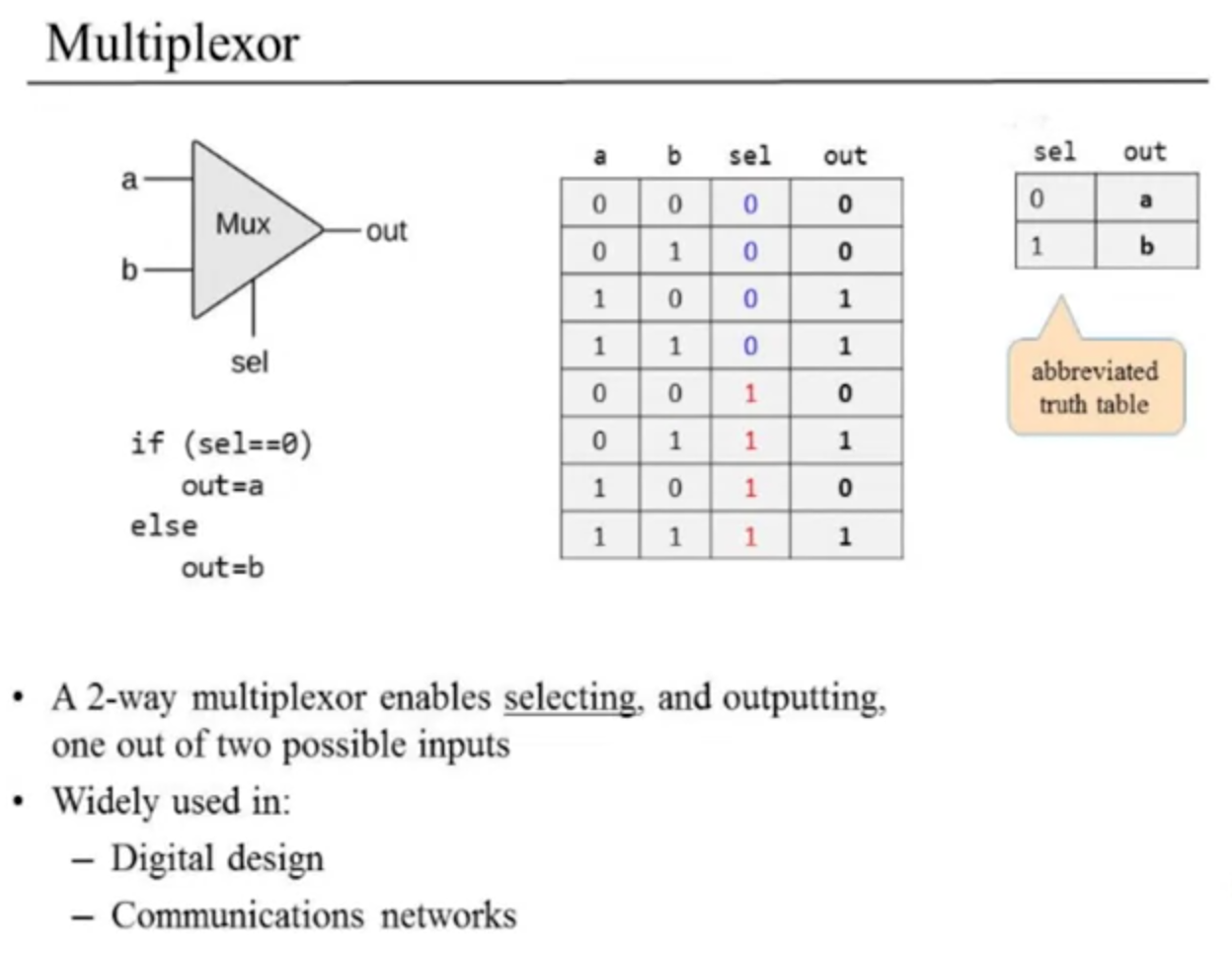
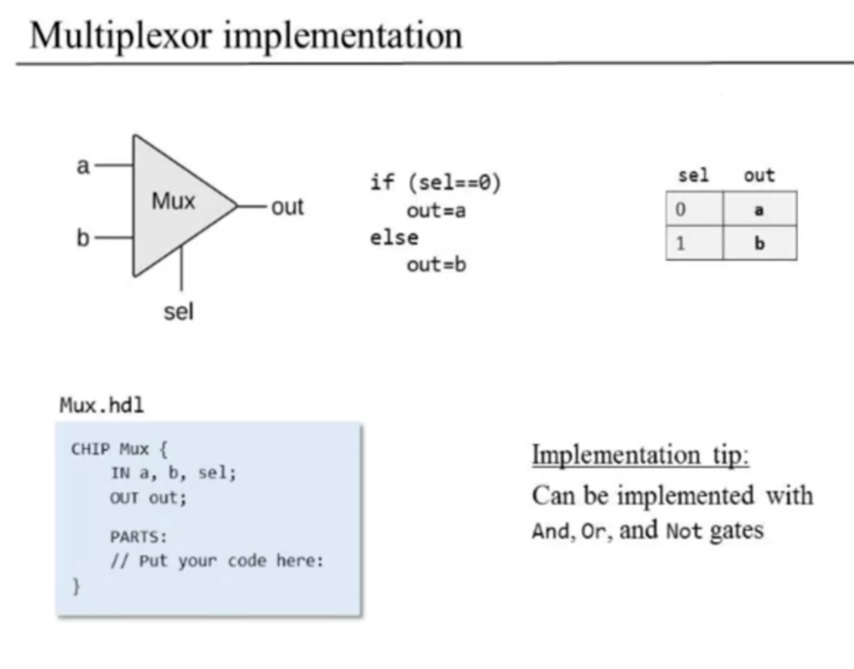
Multiplexor (Mux) and Demultiplexor (DMux)
3 inputs, a+b+sel, chip select. If chip select is low (0), out=a, if chip select is high (1), out=b. Or like this example image:
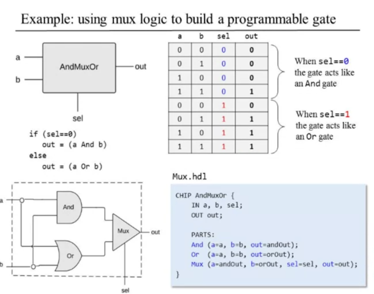
How is mux logic used in programmable gates? He gives an example of an AndMuxOr:
How do we build a multiplexor? Our system architect gives us this, we have to make the Mux ourself :)
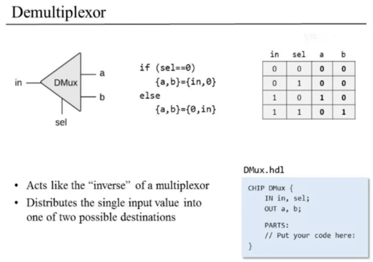
Next a DMux, which is an inverse of a Mux, it's a demultiplexor. Here's the stub file from the system architect:
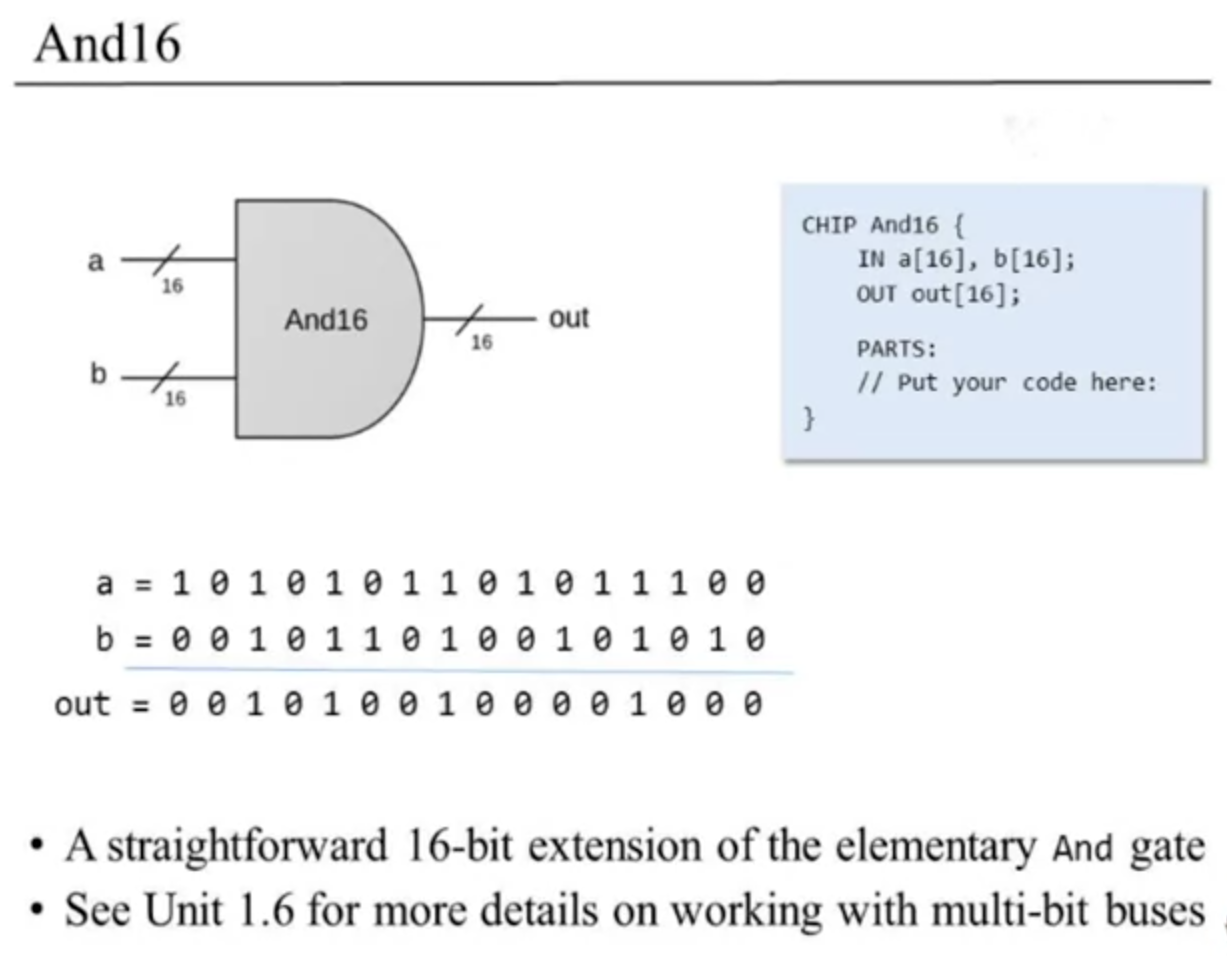
And16
Two 16-bit busses in, one 16-bit bus comes out. Basically it's a way to AND operation both of the entire busses. Here's the example slide:
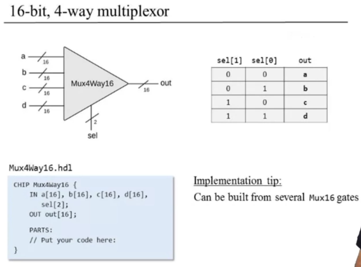
Multi-way variants
This kinda combines the last two explained.
16-bit 4-way multiplexor (Mux4Way16) example:
How to build each of these gates?
He uses xor as an example of how to do this (I think I did this correctly already but we'll see):
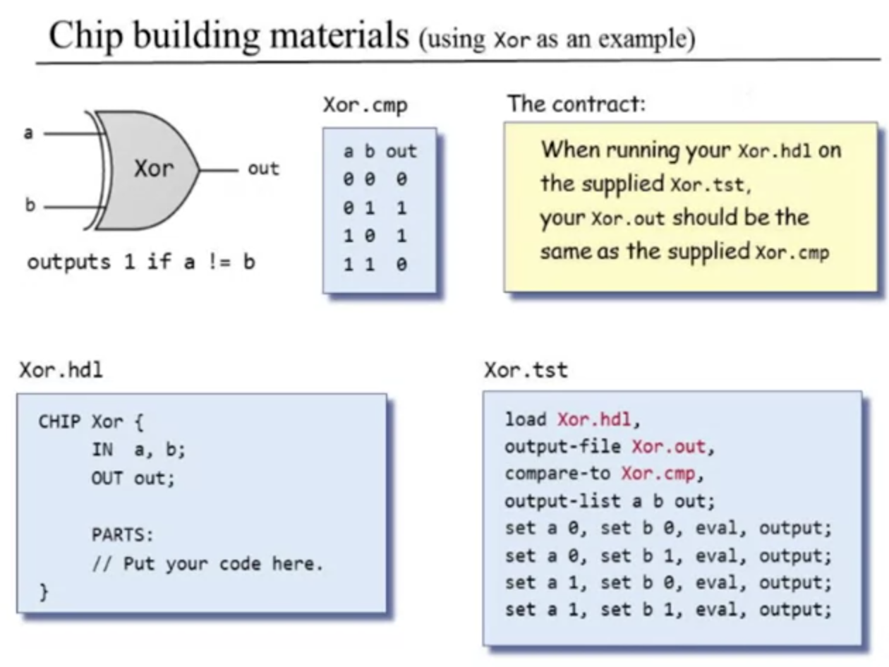
If my test runs and my chip outputs the same as their compare file, then I successfully finished that chip and I can develop the next one.
HACK Chipset API comments
He's explaining the names of the input output pins? If the gates that you use are off-the-shelf gates or part of the hack chipset api, they already provide all of that information about how to use them, like this:
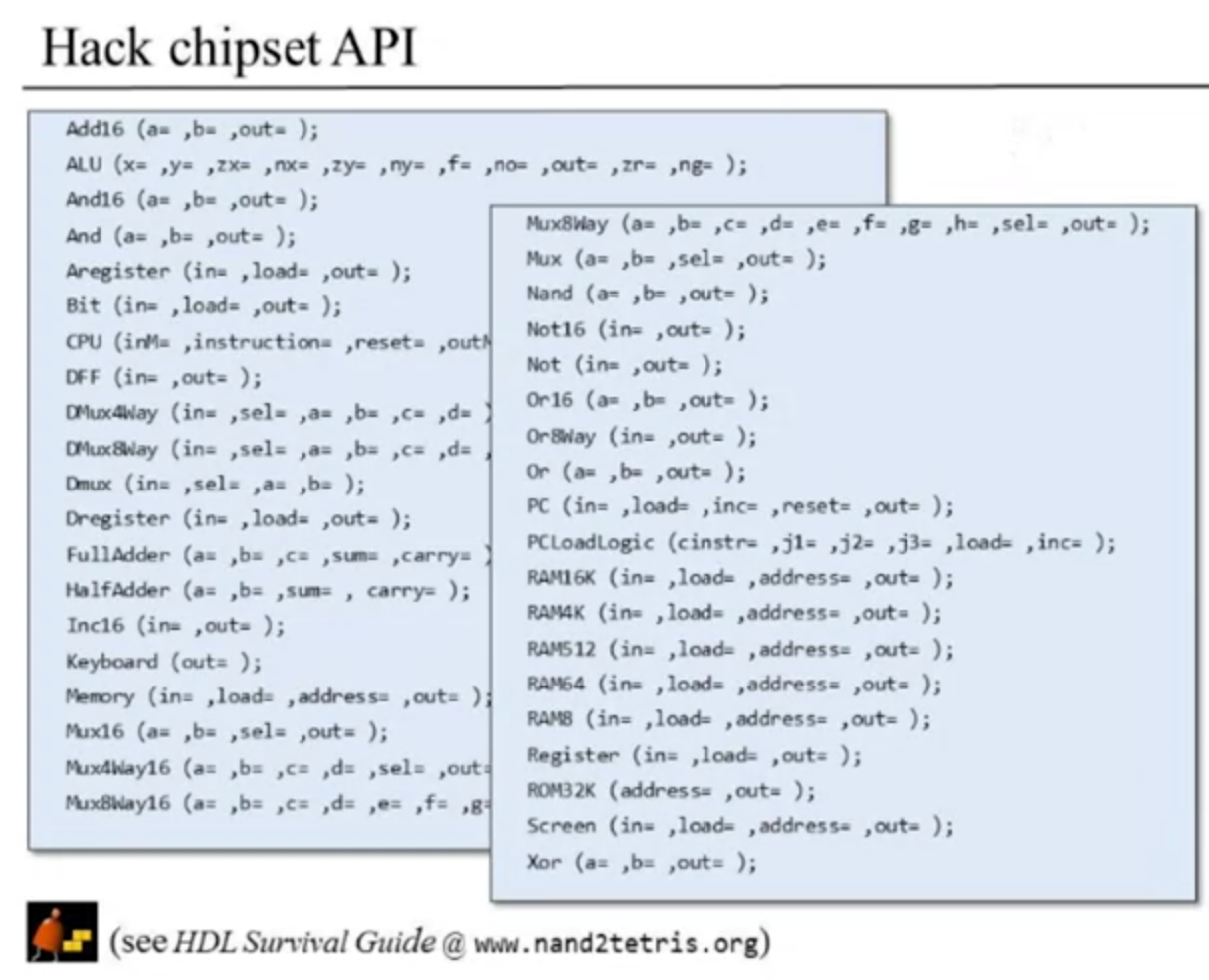
The information is there! :)
Their method of using built-in chips differently is dependent upon the name of the file, which is funny, so they don't self-describe the modules with a module name and they don't use a file list upon their relative compilation (aka simulation). Probably to just cut down performance requirements since it's so old.
He says to use as few chips as possible, but the project is also to make the whole thing from nand. I think my nand only elementary gates is sufficient for that, but could I make more composite gates than the course specifies to cut down on time? Maybe later I make a refactored HACK computer and do it the "verilog" way where I'm not manually making these gates and parsing them out to separate files, I could describe the behavior of the computer instead and all the logic gets inferred by Quartus. I dunno, would be cool if I got that advanced. One step at a time man... one step at a time...
He said a chip cannot be used in it's own implementation. There is no recursion in HDL. I am pretty sure that's the same in verilog and vhdl so yeah. You can define more "chips" (aka modules) within the same file in these languages, but their custom simple HDL doesn't permit that.
For their custom hdl, their bit indexes are ordered right to left (0 upto 15 instead of 15 downto 0). Their simulator probably can't work both ways.
Unit 1.8 - Perspectives
This unit is devoted to some typical questions that come up at the end of each unit. Not really that important, but I'm glad to hear their Q and A session.