How Does Precursor Get to the Reset Vector? - betrusted-io/betrusted-wiki GitHub Wiki
This page documents all the things that happen before Precursor gets to the point of loading the Xous kernel image. In particular, when Precursor is fully powered off, it has zero CPUs: both of its FPGAs are blank and unprovisioned. Something must happen between the application of power to the point where the Xous loader runs to set up the kernel.
If you wonder what that process is, you've found the right document. However, most users can remain blissfully ignorant of the fact that their Precursor actually ships with no hardwired CPUs.
Overview
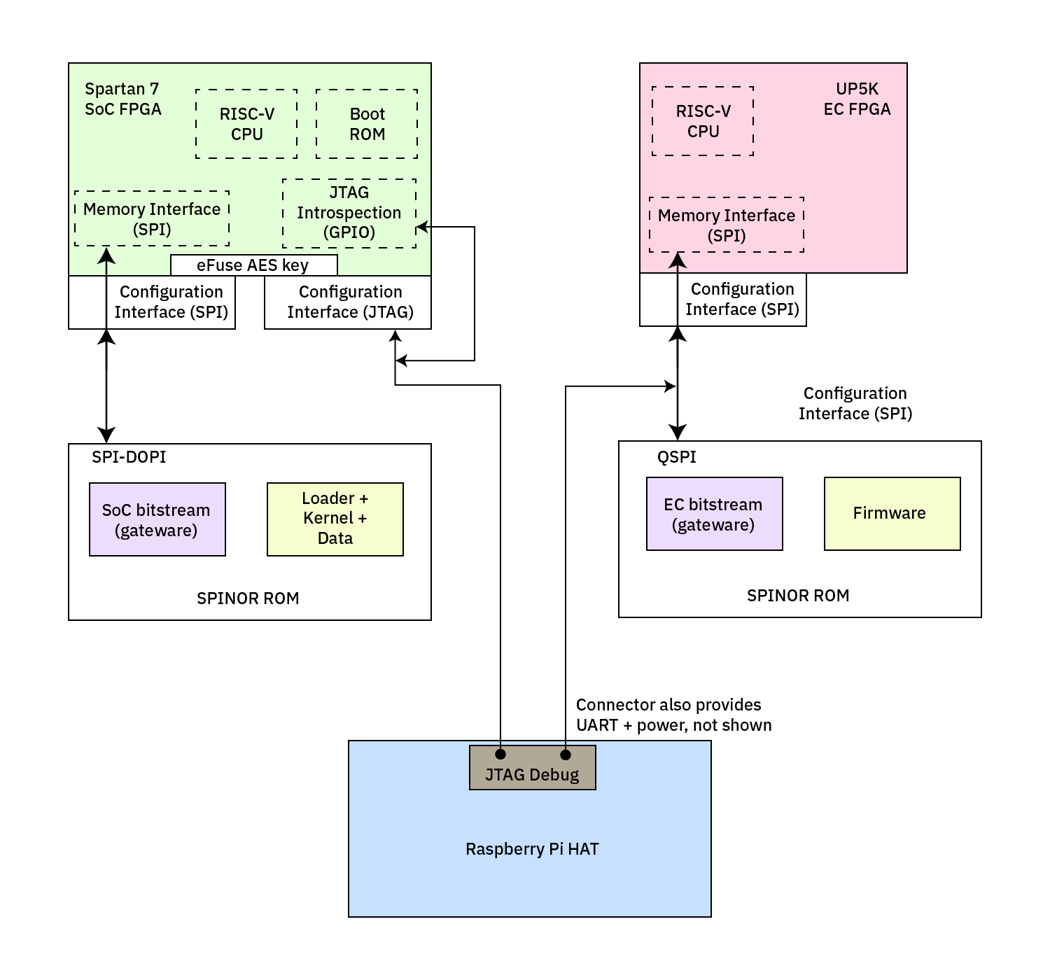
Let's start with a simplified diagram of the relevant players in the pre-boot process, shown below.
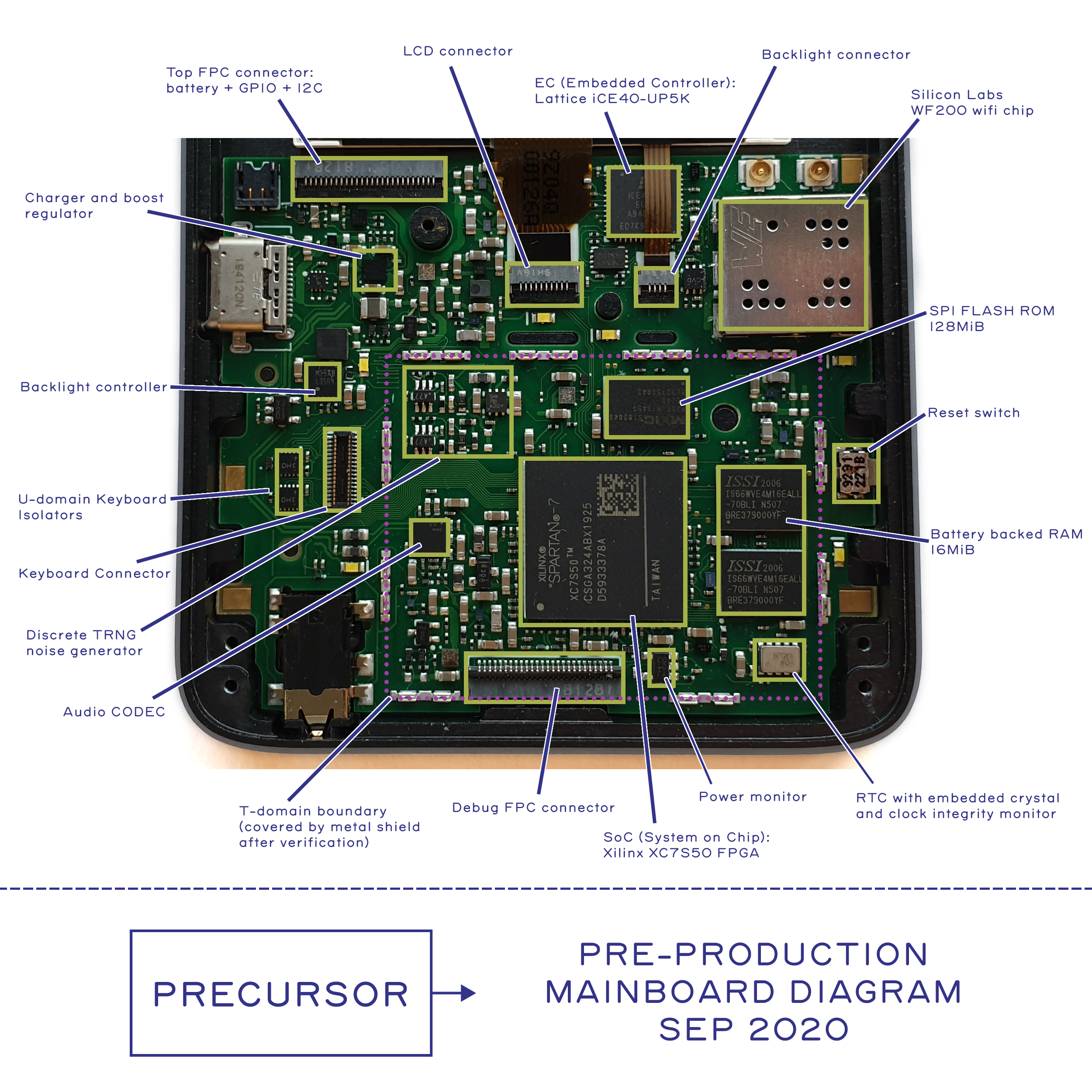
An annotated physical view of the board is also available.
Temporary resources, such as the RISC-V CPU, that are erased when power is lost are shown in dashed line boxes. Items in solid boxes are persistent when power is off.
Spartan 7
The Xilinx Spartan 7 FPGA, at the top left, supports multiple configuration interfaces. For Precursor, we hook up the SPI and the JTAG configuration interfaces.
- The SPI Configuration Interface can drive a SPINOR ROM directly using hard-wired algorithms to retrieve an initial FPGA configuration. The function of this interface is documented in Xilinx UG470, "Chapter 2: Configuration Interfaces".
- Post-configuration, the same SPI pins can be used to drive the SPINOR ROM directly and access it as a regular memory device. This potential is indicated by the ephemeral "Memory Interface (SPI)" block in the diagram.
- The JTAG interface can be driven by a host CPU, and it has powerful configuration, debug, and introspection capabilities.
- The JTAG interface is made available to the optional Raspberry Pi HAT via the Debug Cable. Sealing the trusted domain requires physically gluing this cable port shut.
- For the sake of completeness, this diagram also indicates that the JTAG interface is made available for self-introspection by the FPGA logic via a set of GPIOs. This introspection feature is mainly used for self-provisioning the eFuse AES key.
The "SPI-DOPI" device (DOPI = DDR Octal Peripheral Interface, e.g. 8-bit wide DDR SPI) is a high-speed SPINOR ROM with 128MiB capacity, and it contains the non-volatile FPGA bitstream (colloquially referred to as the "gateware" by the LiteX community), plus artifacts associated with the operating system (loader/kernel/data). A "bitstream" is a collection of bits that, when loaded into an FPGA, configure its function. In this case, the bitstream in the SPI-DOPI device is responsible for configuring all those ephemeral, dashed boxes inside the FPGA, such as the RISC-V CPU, Boot ROM, Memory Interface (SPI), etc.
UP5K
The Lattice UP5K FPGA, at the top right, has a single configuration interface via SPI. It can drive a connected QSPI (Quad-SPI, e.g. 4-bit wide SPI) device to retrieve its gateware, and like the Spartan 7, it can re-use the same configuration pins to drive the SPI device as a regular memory storage unit. Detais on the UP5K configuration interface can be found in Lattice's FPGA-TN-02001-3.2, "Chapter 9: SPI Master Configuration Interface".
Like the Spartan 7, the SPI ROM contains both the bitstream, and artifacts associated with the EC's functional firmware.
Provisioning the ROMs
When Precursor devices are fabricated, they are absolutely blank. This means all of the dashed-box items in the FPGA don't exist, and there isn't even a bitstream in the SPI device. How do we get past this?
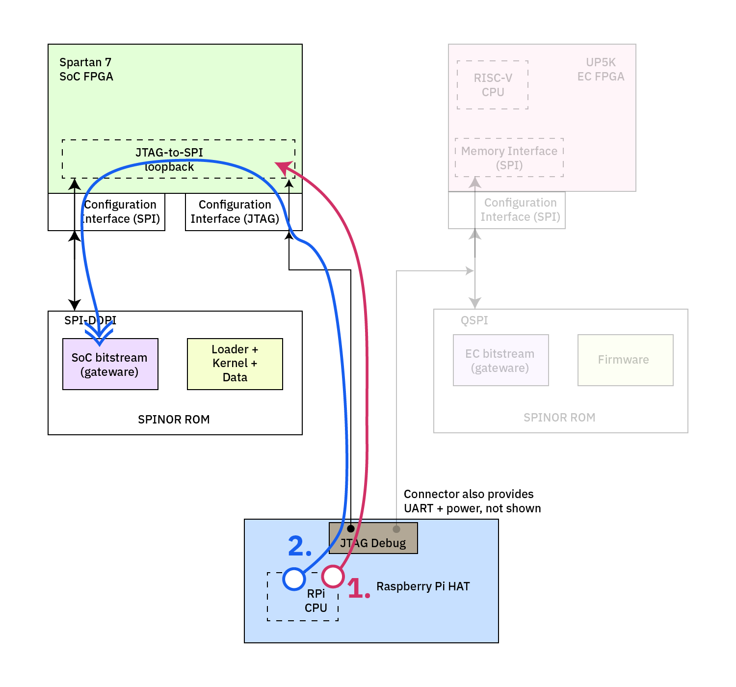
Provisioning the SoC Spartan 7 FPGA
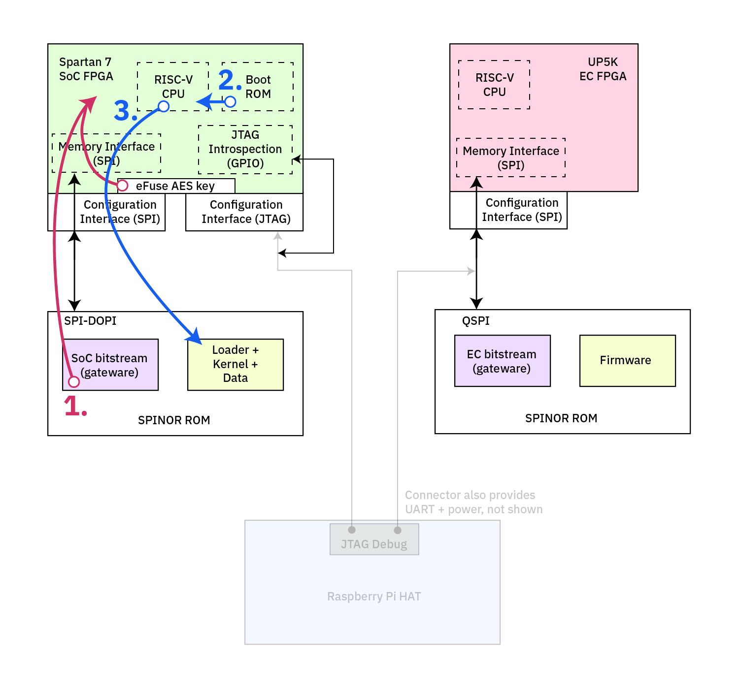
The image below focuses on the answer to how the Spartan 7 is provisioned. images/soc-burn.png
In the first step of provisioning, the Raspberry Pi configures, via the JTAG interface a "JTAG-to-SPI" ephemeral logic using the bscan_spi libraries from Qartiq.
Once configured, the FPGA does nothing but interpret reserved JTAG codes into states on the SPI pins (if you're familiar with JTAG, four TAP registers, USER1-4, are made available by Xilinx to twiddle logic fabric resources via the JTAG port). This effectively creates a path for the Raspberry Pi to "bitbang" the SPI pins via JTAG.
In the second step of provisioning, the Raspberry Pi bitbangs the SPI pins via these JTAG USER TAP registers to write data into the SPI ROM. This includes the SoC bitstream (always located at address 0x0), and then the loader/kerne/data artifacts (locations are not hardwired, but documented).
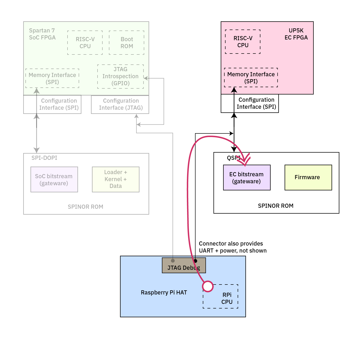
Provisioning the UP5K FPGA
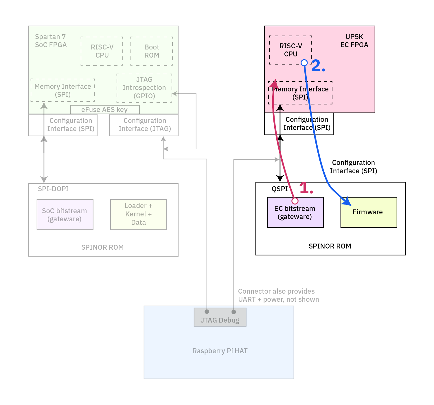
The image below focuses on the answer to how the EC is provisioned. images/ec-burn.png
The EC only supports bitstream-from-SPI operation, and thus the provisioning process is much more straightforward. In this case, we expose the SPI pins directly to the Raspberry Pi via the JTAG Debug cable, and the Raspberry Pi simply co-opts the interface and writes directly to the SPI memory device, while holding the FPGA in reset to ensure there is no contention for the SPI resource.
Once the Raspberry Pi tri-states its SPI drivers, it releases the EC from reset, and the EC automatically loads its bitstream out of the SPINOR device from location 0x0.
While this method is much simpler logically, electrically it's a bit of a mess -- because the SPI pins are directly exposed to the debug cable, it creates an electrical stub, and this limits the performance of the SPI interface.
Booting Up: Configuring the FPGAs
Once the initial data has been provisioned onto the relevant SPI devices, the Precursor device is ready to boot.
Booting the UP5K EC FPGA
Timeline-wise, the EC comes up first, so we'll discuss it first. As soon as power is applied to the Precursor device via the USB-C port for the first time, the EC domain is forced on. Below is a diagram that focuses on the EC boot path.
The EC FPGA's hard-wired Configuration Interface loads a bitsream out of the QSPI device, thus creating the ephemeral RISC-V CPU, its memory interface, and other peripherals not shown for clarity. In the case of the EC, the RISC-V CPU then immediately fetches its reset vector directly from the SPINOR ROM -- its boot instruction is mapped directly into the QSPI device.
For performance reasons, however, the first instructions run by the RISC-V CPU are to copy the rest of the firmware into on-chip RAM, and then it jumps to a local copy inside RAM. Code running in RAM is about 20x faster than code running XIP out of FLASH.
The reader is referred to documentation within the EC repository for further information on how this firmware functions.
Booting the Spartan 7 SoC FPGA
Timeline-wise, the SoC only comes up when its is commanded to power on. This happens by any of the following sources:
- An EC-controlled power-on pin
- Plugging in USB power
- An alarm from the RTC chip
- A self-power-on pin for the SoC
The last item is used to ensure the SoC can stay powered on even if the EC tries to turn it off without its authorization.
-
The SoC FPGA's hard-wired Configuration Interface loads a bitstream out of the SPI-DOPI device, thus creating the ephermal RISC-V CPU, its memory interface, a boot ROM, and other peripherals not shown for clarity. As indicated in the diagram, this bitstream is XOR'd with a CBC-mode AES stream generated from an AES key. Precursor always uses an encrypted image; however, the eFuse is initialized to its default key (0x0) when shipped to users. It is up to a user to provision and burn their own AES key, and a set of tools are made available for this which are still in the process of being refined into a more user-ready tool.
-
The RISC-V CPU fetches instructions from a Boot ROM, which is built into the gateware/bitstream of the device. Thus the boot ROM's provenance is the bitstream image loaded in step 1, but logically it appears as a separate peripheral to the RISC-V CPU. The boot ROM's contents can be found here. As of April 2021, it's a simple jump to the loader, but later on it will be augmented to include features to check public key signatures on the initial kernel image.
-
The RISC-V CPU starts running code out of the SPINOR ROM which loads the kernel and runs it. There are work-in-progress docs on the startup sequence, or you can refer to the code (assembly preamble (note: the assembly preamble is not automatically built, please refer to the README in the loader directory) and Rust main of the Loader, which then sets things up for the assembly preamble and Rust main of the kernel).
And that's it! That is how you get from a blank, no-CPU-but-two-FPGA device to a Precursor that is running a Xous kernel.