Use Data Tables with Table Nodes - anticto/Mutable-Documentation GitHub Wiki
How to use table nodes
This article explains how to create and use a Table Node to create variations of objects with similar characteristics.
Required Assets
There are two assets required to create a Table Node :
- UStruct: This asset will determine the row structure and default values of our Data Table. Each variable of this Struct will generate a new column in our Data Table. Also, this asset allows us to select the Default Asset which helps to set similar properties between all the assets of the same column.

- UDataTable: This asset will store all the asset of the different parameter values. Each column can represent a pin in our Table Node and each row an option for our objects.
Check the node documentation to see which types of columns generate a pin.

Mesh Variation
[!IMPORTANT] There are some conditions to work with Skeletal Meshes within Table Nodes:
- All Skeletal Meshes of the same column should have:
- Same number of LODs.
- Same number of Materials.
- Same Mesh Section structure (Mesh sections must be in the same position).
- Same Layout block Structure. Meshes of the same row share the same layout block structure.
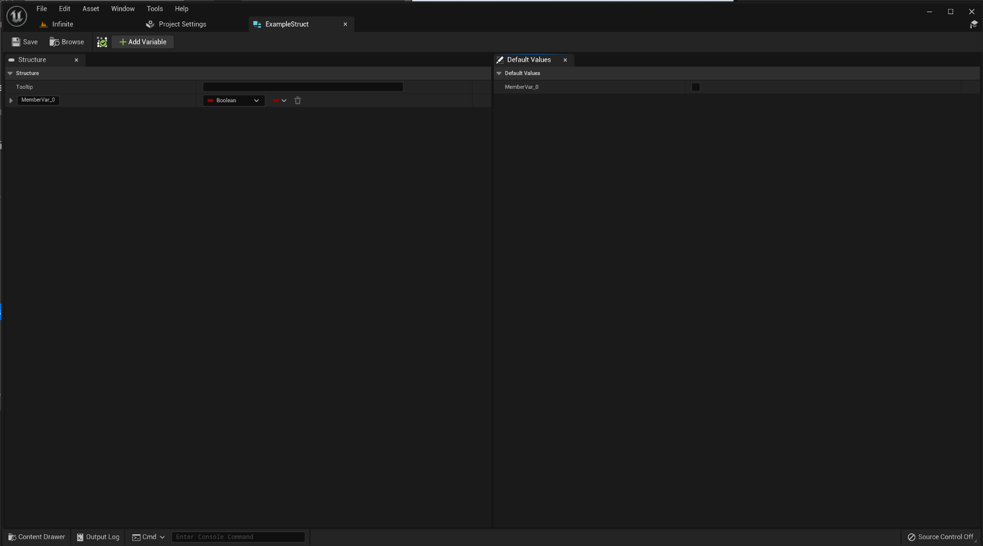
If we want to create a mesh variation with a Node Table first, as we said, we need to create first a UStruct and then a UDataTable. To create a UStruct we just right click on the content browser and then we type "struct" in the context menu that has appeared (Context Menu -> Blueprints -> Structure). We are going to name it "ExampleStruct". If we click on it to open the asset, we will see two tabs:
- Structure: In this tab we are going to define the structure of our data table by pressing the "+ Add Variable" button.
- Default Values: In this tab we are going to define the default values for each variable of the struct.
[!Warning] All UObject variables of the struct must have a default value, otherwise the variable won't appear in the node.
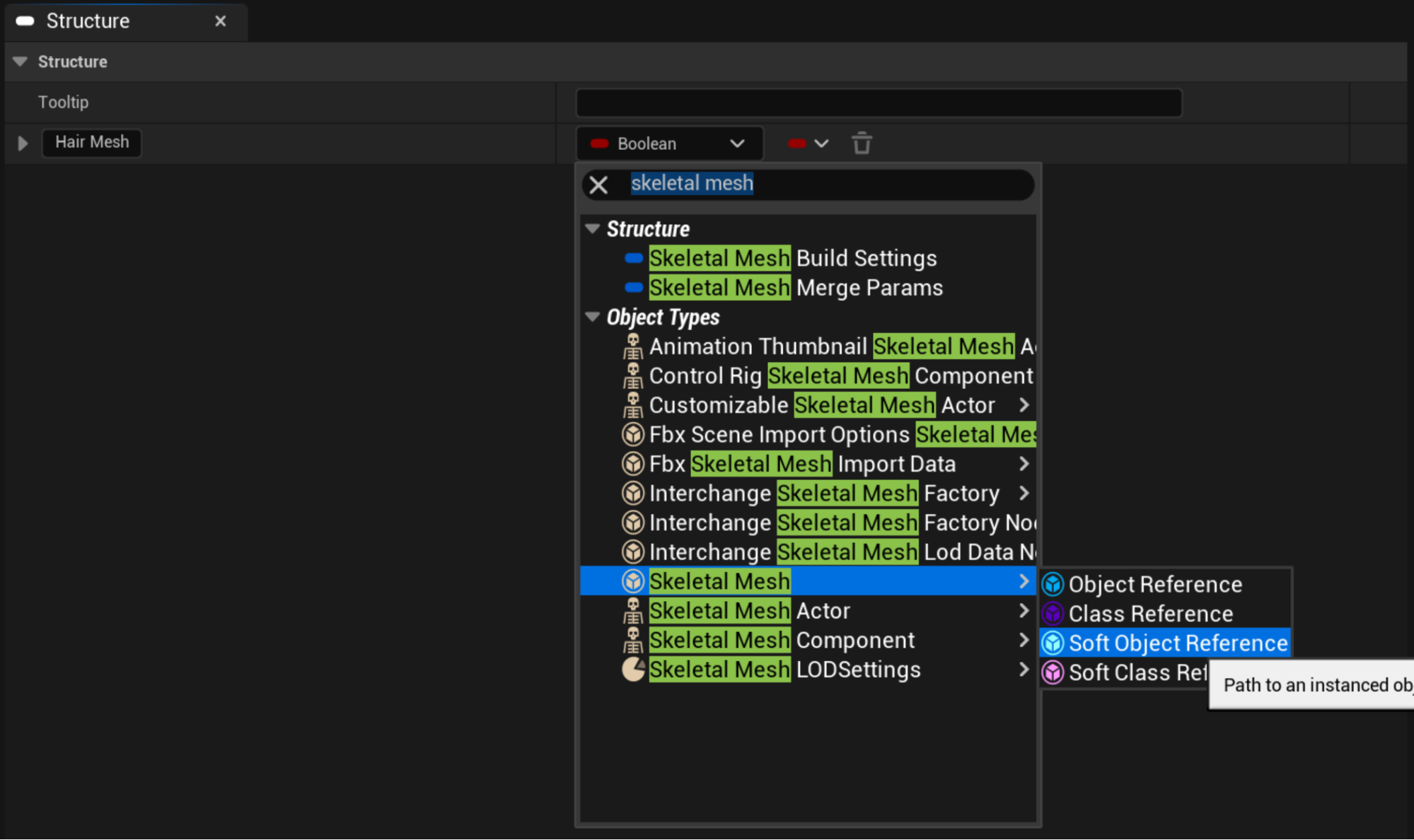
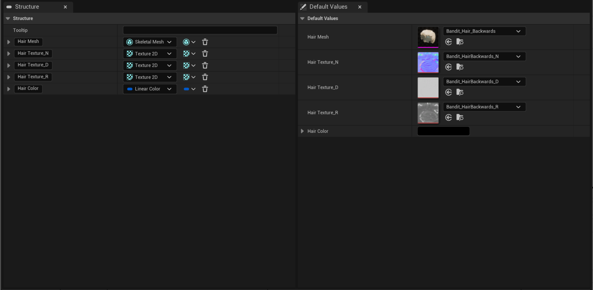
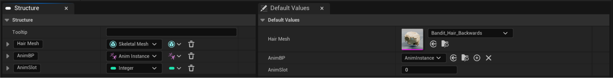
As we already have a default variable created we are going to use it for our mesh. To do so, we have to select the drop down menu which specifies the type of our variable. We are going to search for Skeletal Mesh and the create a **Soft Object Reference". We are going to name our mesh variable "Hair Mesh" which would be the name of the column in our Data Table and the name of our pin in the Table Node.
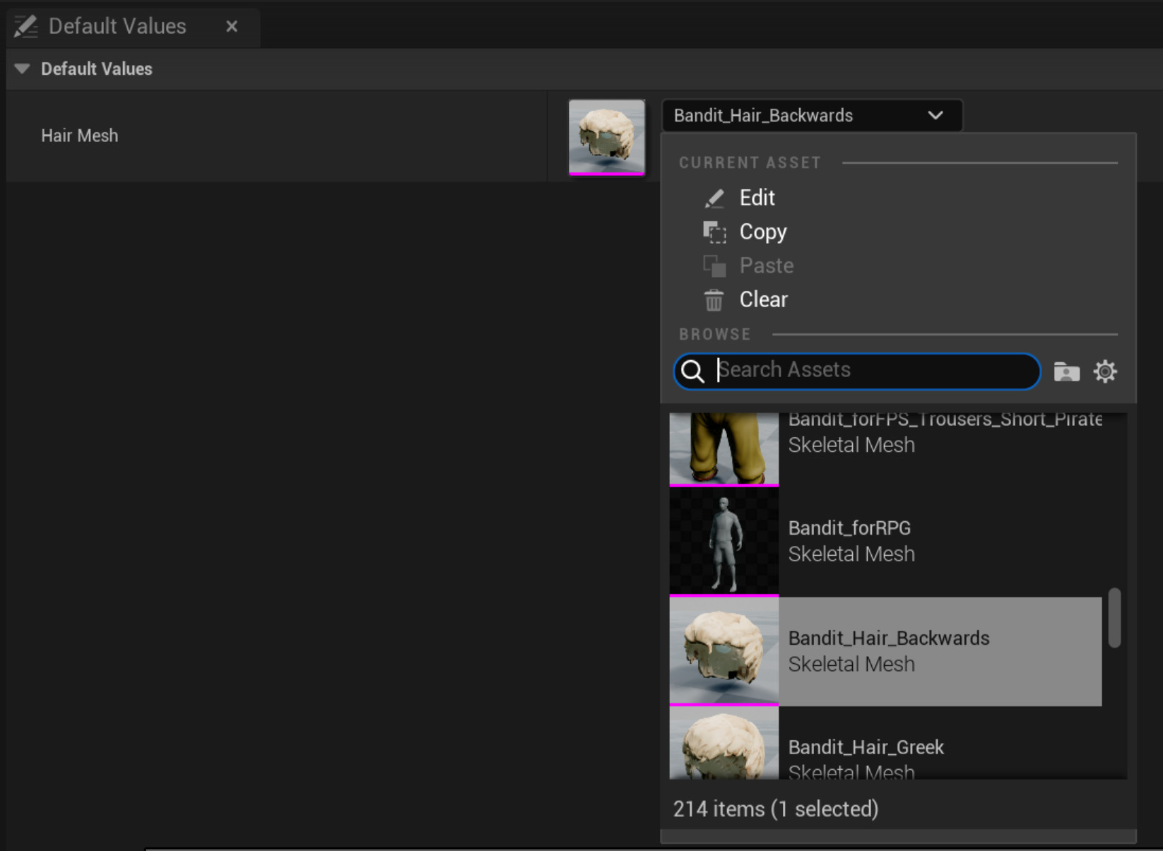
Once we have our first variable, we have to select a Default Value for it in the "Default Values" tab. Take into account that the Default Variable will be the reference mesh for all the meshes of the same column of our Data Table. That means that all the meshes of the same column will have the same Layout and also they should have the same amount of LODs and Materials (Sections). I will select the asset "Bandit_Hair_Backwards" for this example.
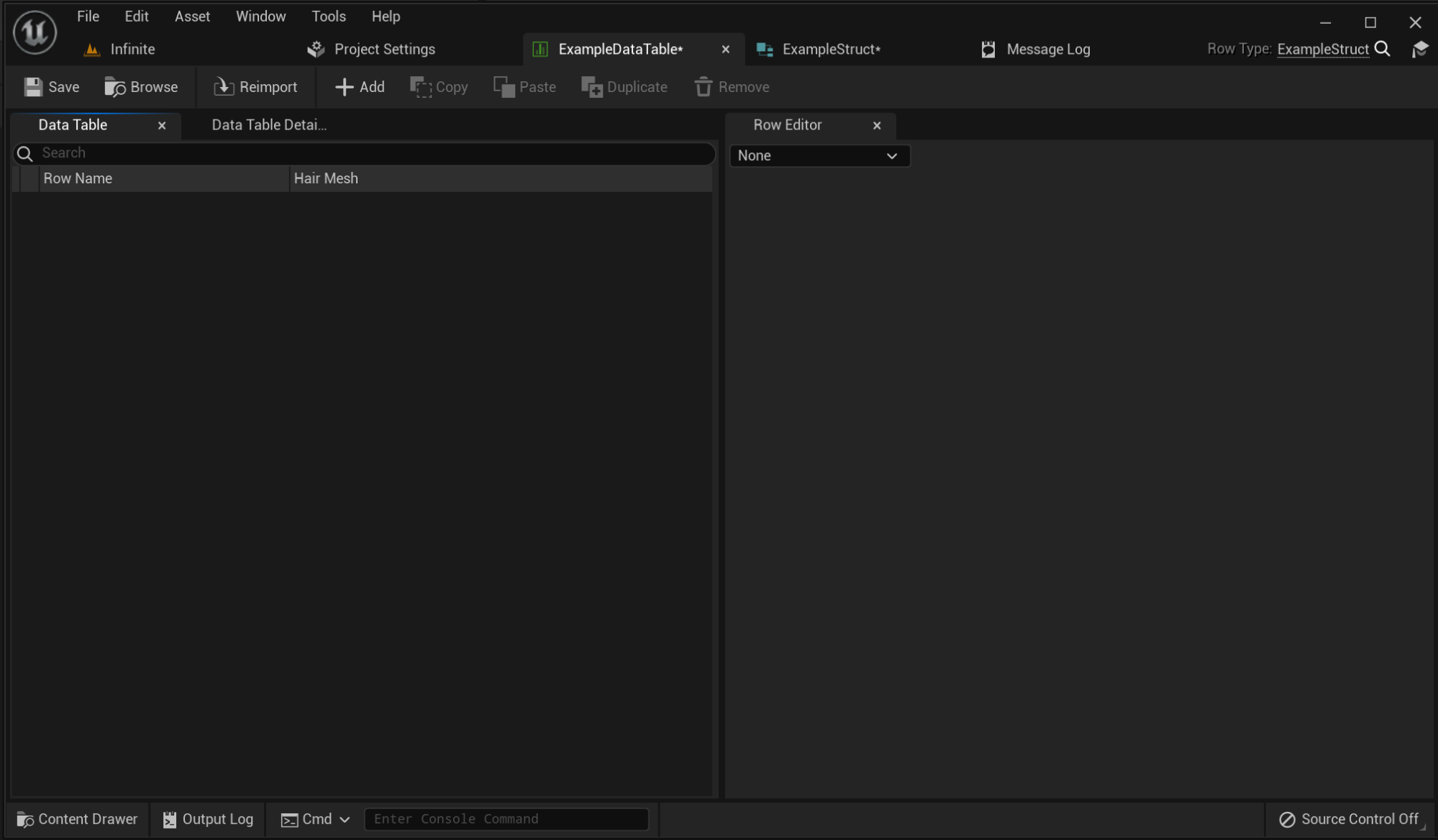
At this point we already set up our Structure. Now it's time to create and set up our Data Table. To do so, we right click on the content browser and we type "Data Table" in the context menu (Context Menu -> Miscellaneous ->Data Table). We are going to name it "ExampleDataTable". If we open it, we will see that there are three tabs:
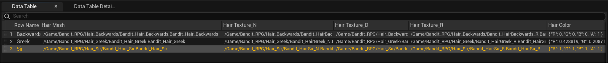
- Data Table: This tab shows the information of each row and columns of the table. Right now there are two columns, one for the name of the row "Row Name" (automatically generated) and another one for the variable that we just created in the Structure "Hair Mesh".
- Data Table Details: Tab with some information of the table. We are going to ignore it.
- Row Editor: Tab to select the assets that we want to use for each row.
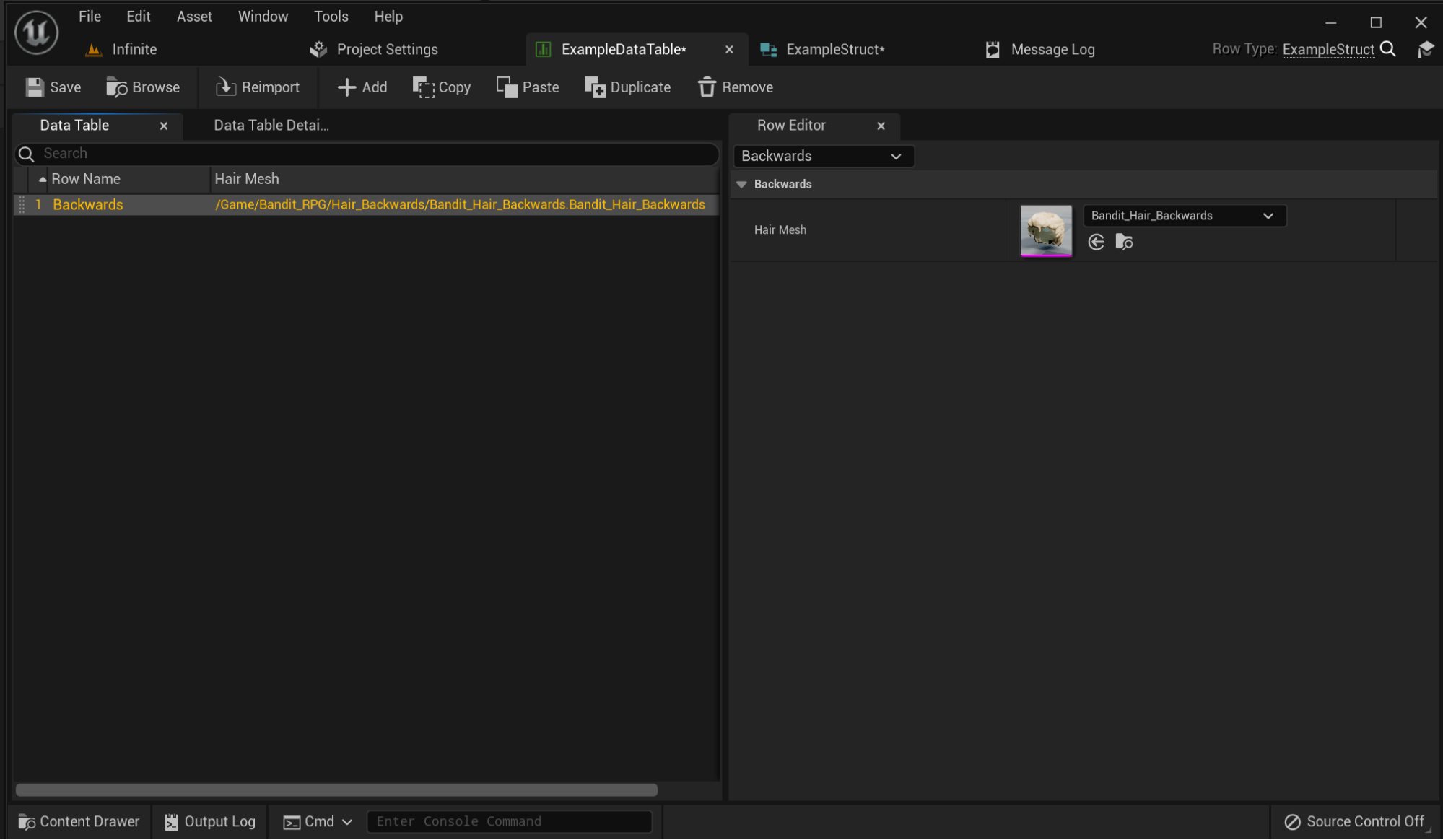
Now is time to fill our Data Table to create some mesh variations. To do so, first we have to add a new row by clicking on the "+ Add". This will create a new row with the default values. We are going to keep the mesh with the default value and we are going to change the row name to "Backwards". This name is the one that will appear in the variation selector of our UI.
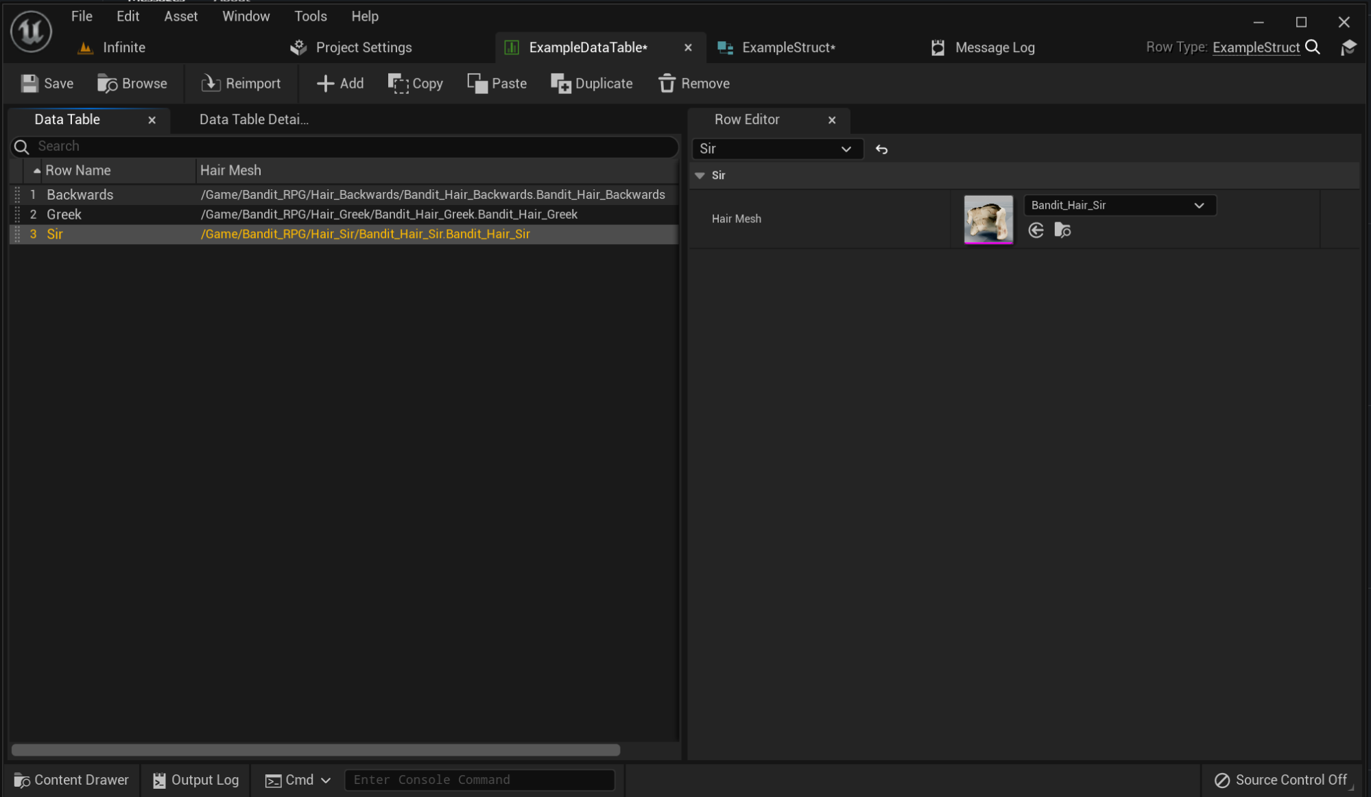
We are going to create two new rows with the following Skeletal Meshes: "Bandit_Hair_Greek" & "Bandit_Hair_Sir".
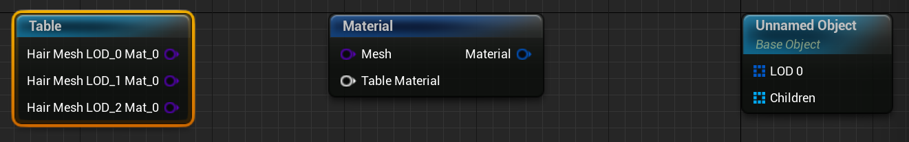
Now we have our Data Table set up. It is time to create our Customizable Object and test our Table Node. We are going to name our Customizable Object "TableNodeCustomizableObject". Once we have opened our Customizable Object, we need to create two nodes: a Table Node and a Material Node.
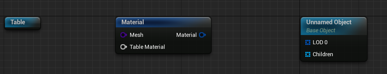
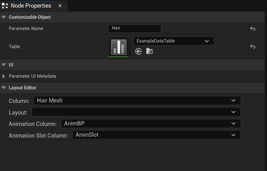
Our Table Node doesn't have any pin because it doesn't have any Data Table assigned. To select a Data Table for our Table Node we have to click on the node and then fill the property Table, in the Node Properties tab, with our Data Table "ExampleDataTable". We will name the parameter as "Hair".
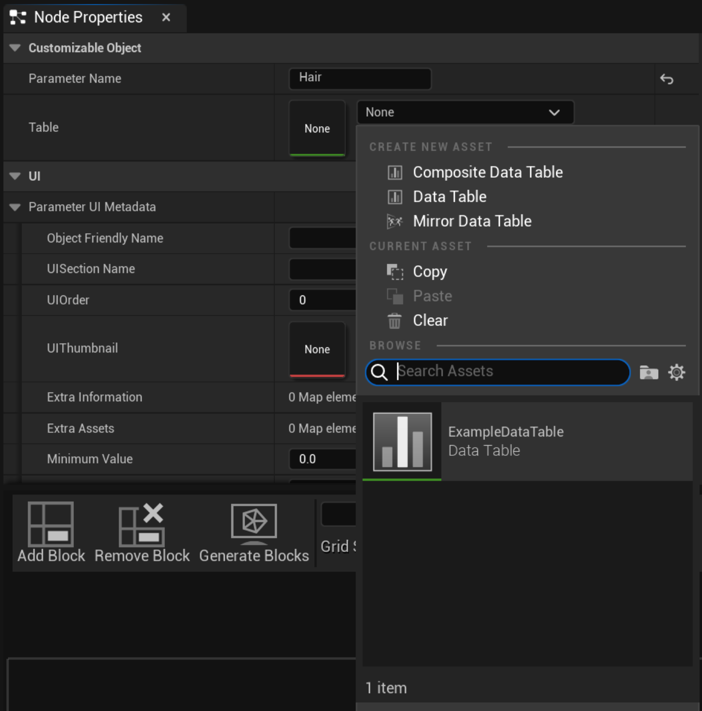
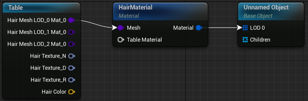
We will see how the node refreshes automatically after select the Data Table and our mesh pins appear.
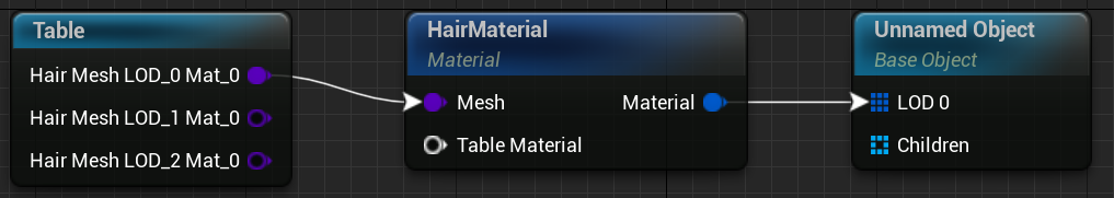
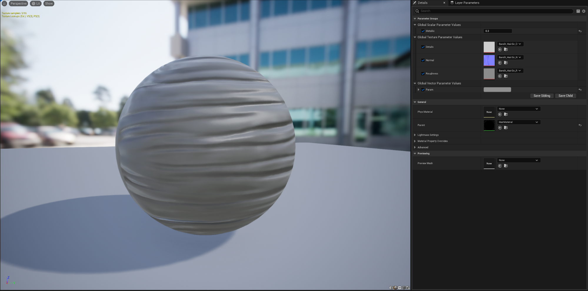
Now we can connect the first LOD pin to the Material Node and connect the Material Node to the Base Object Node. We will select the material "HairMaterial" for our Material Node and then we will compile our Customizable Object.
Results
Texture, Colors and Float Variations
We can see in the results of the previous example that there are some visual artifacts in the Greek and Sir meshes. This is because we are using the same textures (Roughness, Normal, Details) for all the meshes and we should not. With the Table Node we can also create texture variations. To do so, we are going to create three new Texture 2D variables (Soft Object References) in our struct, one for each texture of the material (Roughness, Normal, Details). The default values would be: "Bandit_HairBackwards_D", "Bandit_HairBackwards_N", "Bandit_HairBackwards_R". We will also add a color variation to distinguish each type of hair. To do so, we will have to create a Linear Color variable and we will let the black color as default.
Each new variable has created a new column in our Data Table, let's fill each row with the corresponding textures and colors. For the backward hair we will use the default values. For the greek hair we will us a brown color and the following textures: "Bandit_HairGreek_D", "Bandit_HairGreek_N", "Bandit_HairGreek_R". For the Sir hair we will us a white color and the following textures: "Bandit_HairSir_D", "Bandit_HairSir_N", "Bandit_HairSir_R".
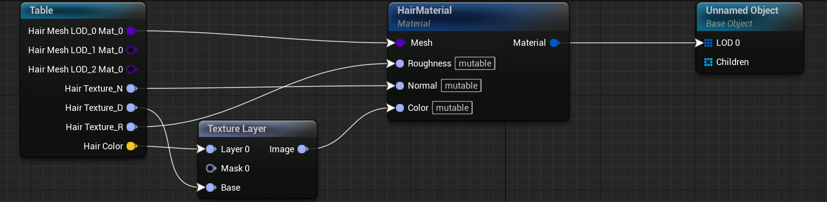
If we refresh our Table Node our new pins will appear.
Let's connect these textures to our Material Node and compile. For the color parameter of the Material Node we will generate a texture by linking our color parameter and the Texture_D to a Texture Layer Node.
We could also use a float variable to control some float parameters of the material, like the metallic parameter.
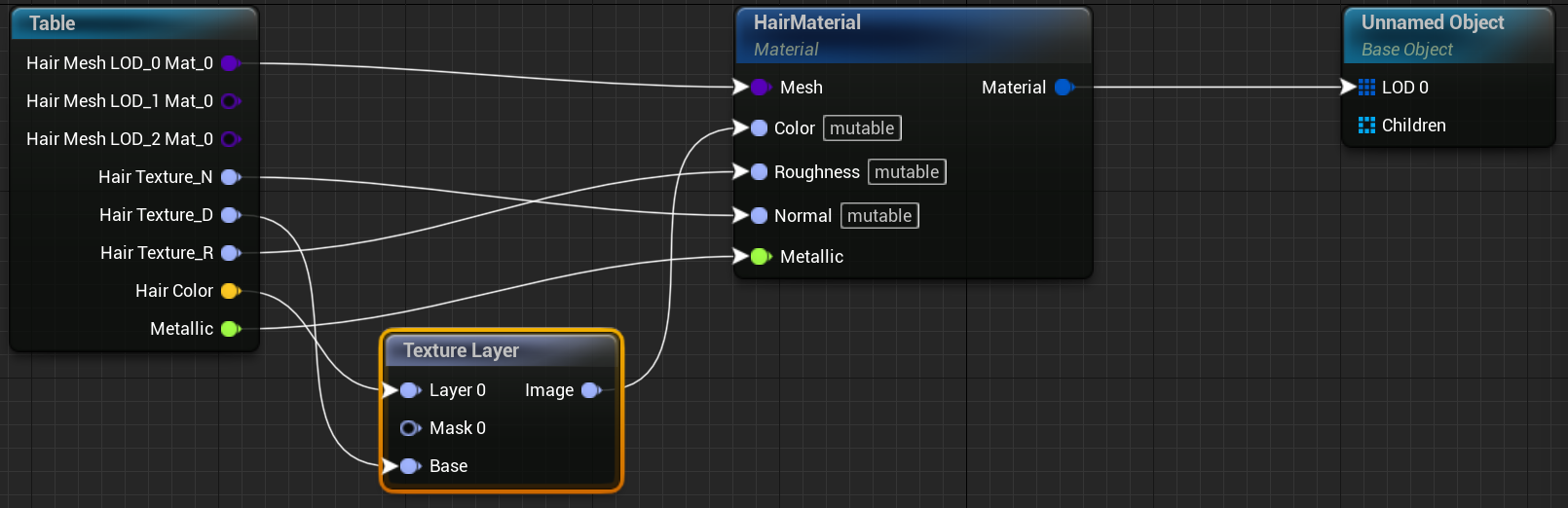
[!Note] We can convert a Mutable Texture to an Object Texture using the pin viewer or by right-clicking the Texture pin we want to change. This also works to convert an Object Texture back to a Mutable Texture.
Results
Using Material Instances as Presets
We can use material instances to clean a little bit the graph and have better control of the variations. To do so, we are going to delete all the textures, floats and color variables from our structure. Then, we will create a material instance variable (Soft Object Reference). We are going to name it "Hair Material". However, before selecting a material instance, we have to create them. We will create three material instances from our material "HairMaterial": "HairMaterialBackwards", "HairMaterialGreek" and "HairMaterialSir". In each of this instances we will modify the parameters to match the values from the last example.
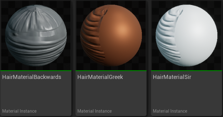
Now that we have our material instances, we have to select a default value (we will use the "HairMaterialBackwards") for our Structure and then, fill the values of our Data Table rows. Once we have all set up, we will have to refresh our Table Node. All the texture pins will disappear and a Material Pin will appear. Link this material pin to the Table Material pin of the Material Node and compile.
[!Important] All the instances of the row should be instances of the same material. If we need to use instances that have a different parent, we have to check the option Disable Table Materials Parent Check (Compile Options section). If we check that option we have to be sure that the material parameters that are going to be modified have the exact same name in all the parent materials.
[!Important] The reference material of the Table Node must have the same parent than the material set in linked Material Node.
Results
Animation Instances, Animation Slots and Animation Tags
We can select which animation instance, an animation slot and animation tags we want to use for each Skeletal Mesh row. To indicate which animation properties will use each skeletal meshes of a column, we have to create three new variables in our Structure: an UAnimInstance, which has to be a Soft Class Reference, an Integer variable and a UGameplayTag.
NOTE: We won't see new pins in our Table Node because these variables do not need a pin to work.
Once we have added these new variables, we can fill the information in the Data Table. Then, to indicate which animation instance, slot index and tags uses a skeletal mesh, we have to use the Table Node properties tab. In the "Animation Properties" section we will see that if we select a mesh column in the "Mesh Column" parameter, three new comboboxes will appear. In this comboboxes we can select the columns that contains our information. These comboboxes are type specified so, for example, the option "Animation Blueprint Column" will only show columns of type UAnimInstance. Each Skeletal Mesh of the column will use the Animation Instance, Animation Slot and Animation Tags of its row.
[!Note] We can have more than one column of each type in our Data Tables.