COGO Tools: Drawing Lines - anthonyblackham/GIS-Wiki GitHub Wiki
Many official documents that involve property will have surveys or references to documents with surveys. Some might have sketches or diagrams but there are many that only have a written legal description. COGO tools enables you to map out the written legal descriptions.
Setting the Stage
How you configure COGO Tools largely depends on the type of survey you are trying to map. Generally it falls into two categories.
- Center Line
- Area
A survey describing a center line will typically be described something like "Being a strip of land six (6) feet in width extending three (3) feet on each side of a center line..." then it will typically follow the calls until the endpoint then we can just buffer out the centerline the labeled distance to create the final polygon.
A survey describing an area will typically have a point of beginning and then it will follow out its calls and then end right back up at the point of beginning so it is a closed polygon.
Units and Bearings
See ESRI's documentation HERE
Depending on how old the document is and where you are in the world it might describe calls in units of feet, metres, or chains and rods. Generally people nowadays in the United States use a HARN stateplane coordinate system (which is Feet or International Feet) which will also typically match any U.S. CAD based surveys as those are usually in feet as well.
Bearings are also described in a myriad of ways: Polar, North Azimuth, South Azimuth, or Quadrant Bearing. Most of the documents I've seen are Quadrant bearings.
You can change your units through the editor toolbar
- Customize >> Toolbars >> Editor
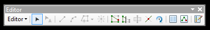
- Click the editor dropdown and select
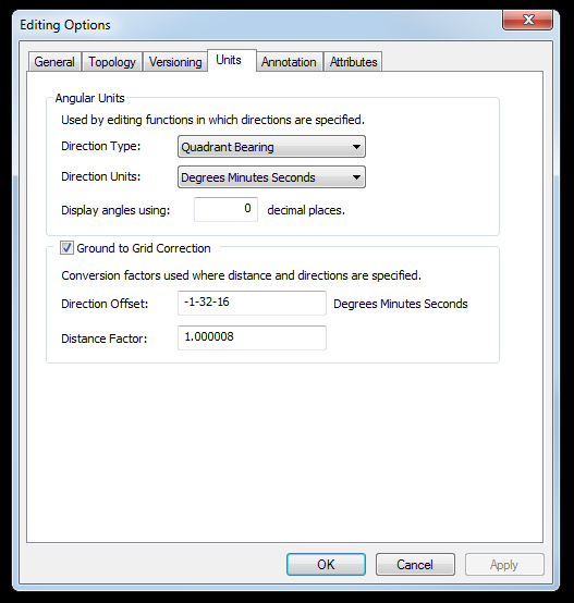
Options - Click on the
Unitstab - Change
Direction TypetoQuadrant Bearing - Change
Direction UnitstoDegrees Minutes Seconds
The example I'm going to be using is in Oregon based on the Oregon Stateplane North Coordinate System (EPSG 2913) with a line feature class
The Legal Description
The following is taken from a typical legal description:
"... assigns a perpetual easement and right of way under and across the following described parcel of land situated in Multnomah County, Oregon being a strip of land six (6) feet in width extending three (3) feet on each side of a center line more particularly described as follows:"
Beginning at a point on the South line of the North 89 feet of Lot 11, PEAKE BROTHERS HOME TRACTS, located in Section 32,
Township 1 North, Range 3 East, Willamette Meridian, said point begin East 22.97 feet from the West line of said Lot 11;
RUNNING THENCE South 84 Degrees, 35 Minutes, and 35 Seconds East 91.67 feet; THENCE South 6 Degrees, 32 Minutes, and 45 Seconds West 65.52 feet;
THENCE South 3 Degrees, 24 Minutes, and 15 Seconds East 57 feet, more or less, to a point on the South line of Lot 10
The legal description has a lot of words, so lets simplify it into just the calls:
N 89-58-53 E 22.97 (the bearing was generated from the property line of my parcel data)
S 84-35-35 E 91.67
S 06-32-45 W 65.52
S 03-24-15 E 57.00
Sometimes the hardest part about a legal description is finding the basepoint, once the basepoint has been found, drawing out the calls is a simple enough task. I was able to find a GIS dataset of the county parcels along with a pdf assessor map that shows me the neighbourhood and lot listed in the legal description. For the purposes of this exercise the basepoint is [7698024.236, 681995.698] equivalent in lat long is LAT: 122°28'0.72"W LONG: 45°31'13.782"N
Drawing a Traverse
Assuming you have your respective feature class created with the correct coordinate system we can now get started
- Add COGO toolbar: Customize >> Toolbars >> COGO
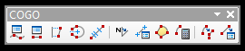
- Select the traverse icon

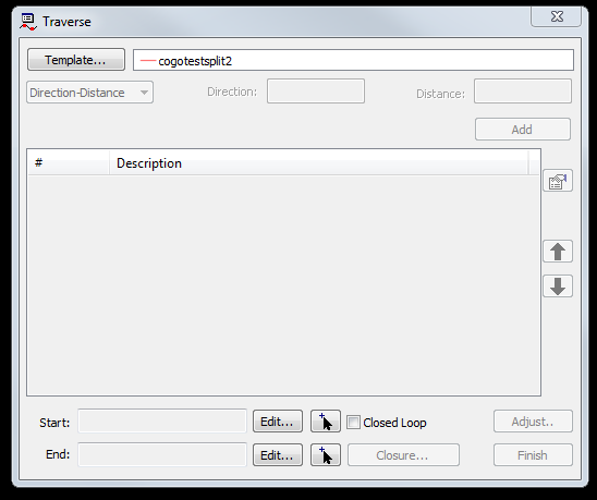
- Select your basepoint (You can click on a location on a map or type in coordinates)

Then we start by typing in our direction and distance for each call (see also ESRI docs. Once we have finished all of the calls it will look something like this:
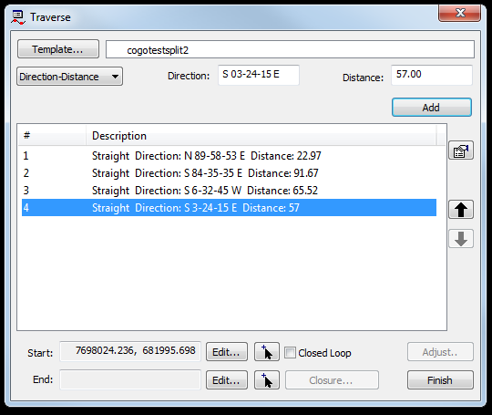
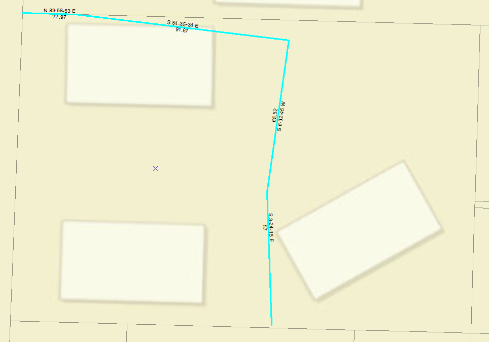
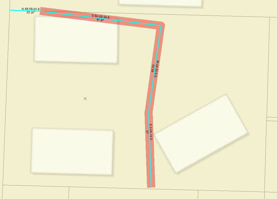
Don't forget we aren't quite finished, since this is a center line and it really is describing a width we need to buffer it out the described 3 feet on either side:
Save Traverse
We can also right click and save as a text file for future reference if we need to reload it, otherwise you can just click finish and it wills save your feature.
The saved traverse text file looks something like this traverse.txt
DT QB
DU DMS
SP 7698024.236 681995.698
DD N89-58-53E 22.97
DD S84-35-35E 91.67
DD S6-32-45W 65.52
DD S3-24-15E 57
DT: quadrant bearing, DU: degrees, minutes, seconds, SP: starting point (x,y), DD direction/distance (FT) You can also right click in the traverse window and load the above text file
Load Traverse From Sketch
If you want to generate a traverse based on something that you have drawn you can select your feature, right click and select edit vertices, then within the traverse window you can right click and select load traverse from sketch and it will generate calls for all of the lines. This is by no means a replacement for an actual survey but it can help give you context.