kicad export frame - andreika-git/hellen-one GitHub Wiki
How to export a frame from Kicad?
If you created a Kicad project for a new Hellen-One Frame and didn't use any existing projects as a template, then you'll need these instuctions to setup Kicad properly. You can use one of our open-source frame examples as a reference for your project:
First of all, let's use the name "gerber" for the folder to store all exported files, including gerber and NC drill files, schematics in PDF, BOM and CPL in csv, and 3D component models in VRML (WRL).
- Open the schematics editor and specify the schematics export settings (File->Plot) as follows:
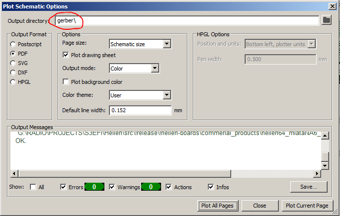
Please notice the "gerber" folder name. Press "Plot All Pages" to save the schematics in PDF file inside "gerber" folder.
- Also add a new field to the script list for BOM export settings (Tools->Generate BOM...):
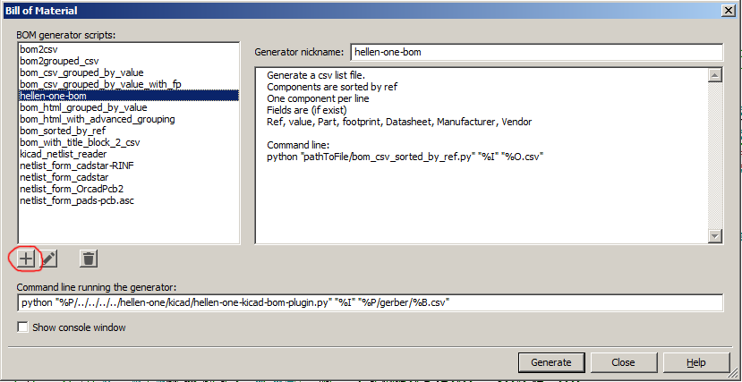
It's important to specify the correct path to the Hellen One folder containing the existing python script (which will be used to export BOM in the specific format). You can use the relative path to your project folder, as shown on the screenshot. Also please notice the "gerber" folder name in the parameters of the script. Press "Generate" to create a BOM file in that folder.
python "pathToFile/hellen-one-kicad-bom-plugin.py "%I" "%P/gerber/%B.csv"
- Then open the PCB editor and make sure you prepared the PCB project correctly:
-
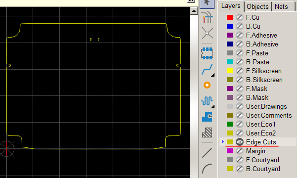
Create a closed border for your frame on the "Edge cuts" layer:
-
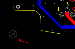
Set the origin points to the left bottom corner of the frame. It should be perfectly aligned with the border lines on the "Edge cuts" layer:
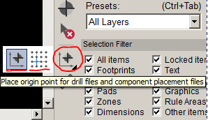
You should see the red crossing with a circle in the corner:
- Now set the Gerber export settings (File->Fabrication Outputs->Gerbers...):
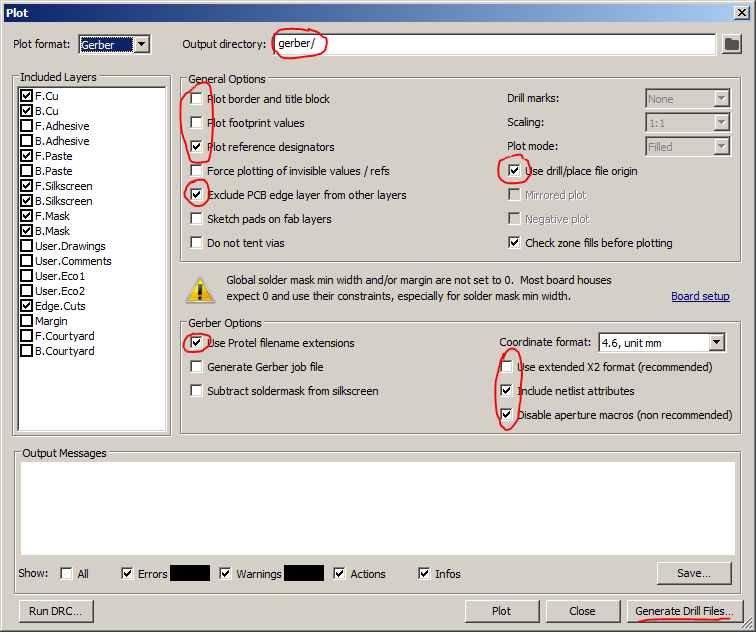
Press "Plot" to save the gerber files.
- Also check Drill settings and generate the files (File->Fabrication Outputs->Drill Files...):
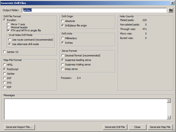
Press "Generate Drill File".
- Then change the "Component Placement" settings and generate the CPL files (File->Fabrication Outputs->Component Placement...):
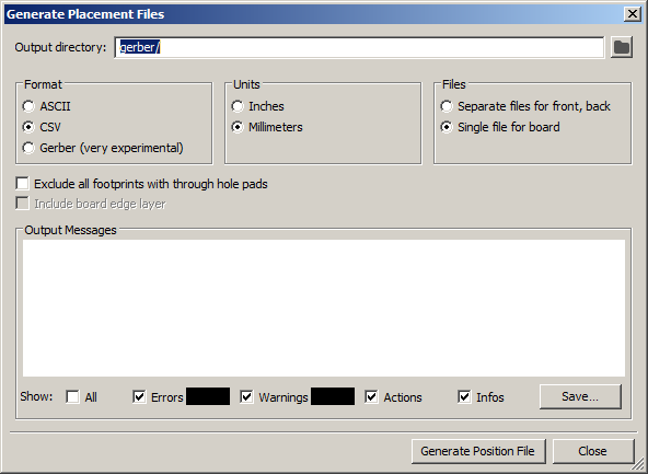
Press "Generate Position File" to save the CPL file in .csv format.
- Finally, open the VRML export settings (File->Export->VRML...):
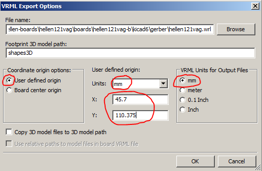
Make sure to specify the correct file path to the gerber/hellenXXXyyy.wrl (the file name should already match the frame name, you should just specify the "gerber" folder to store the file). Also it's important to specify the correct coordinates for the origin. It should match the board origin which has been set earlier. You can find the exact numbers inside the .kicad_pcb file under the names "aux_axis_origin" and "grid_origin".
- Take a look inside the "gerber" folder. You should see the following file list:
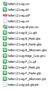
The real file names in your folder should match the name of your frame project (.gbrjob file is optional).
- Check the results.
If you see a disrupted board image, then maybe you may want to specify an image offset: