vB7 Main Board - alanbjohnston/CubeSatSim GitHub Wiki
This archived page is for building the vB7 main board. The latest version of the instructions for the v1.0 board is here.
To assemble the Main board, you will need these tools:
- Soldering iron and solder
- Hot glue gun (helpful)
- Small Philips screwdriver
- Small flathead screwdriver
- Needle nose pliers
- Side cutters
- Wire strippers or a blade
- Heat gun or hairdryer
Main Board Instructions
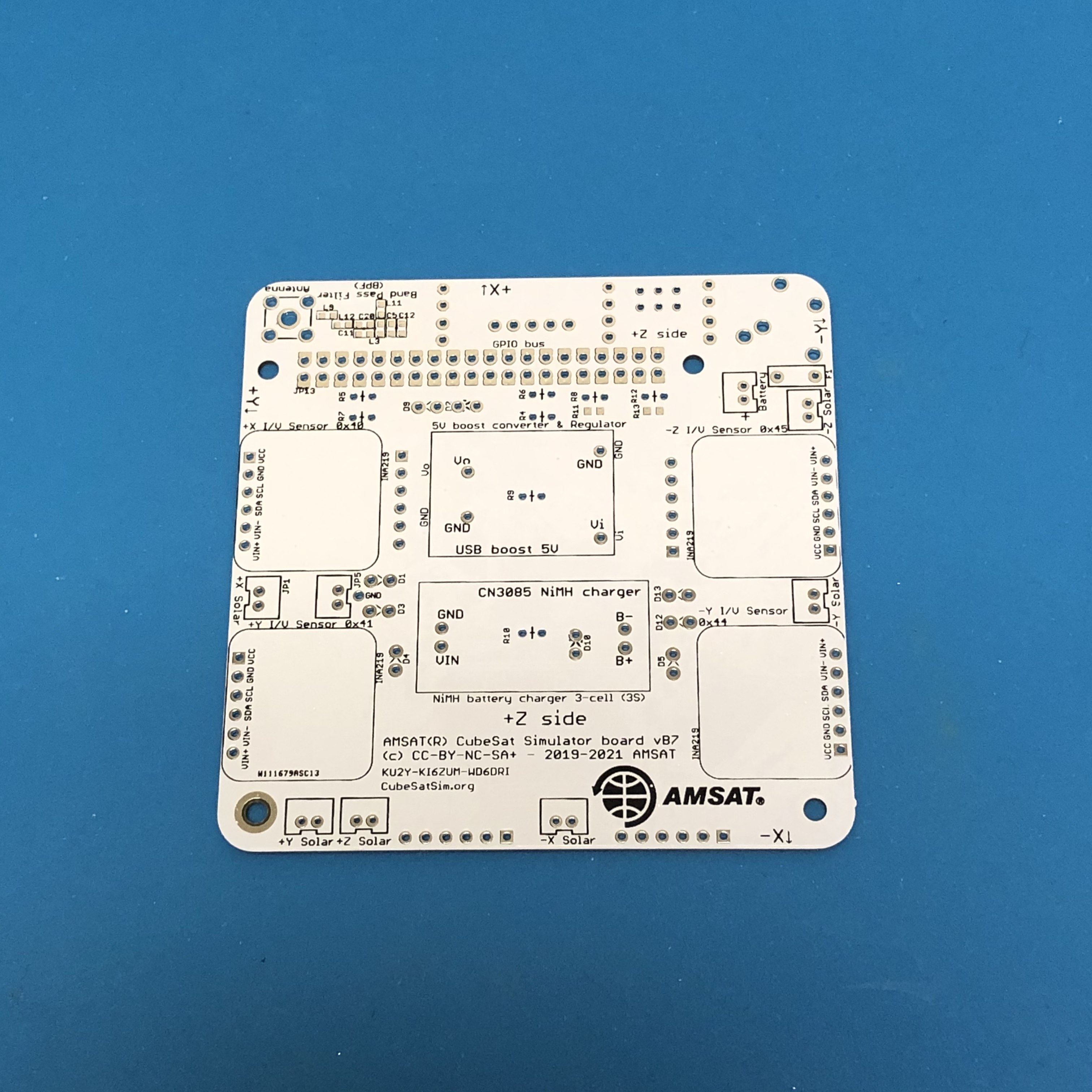
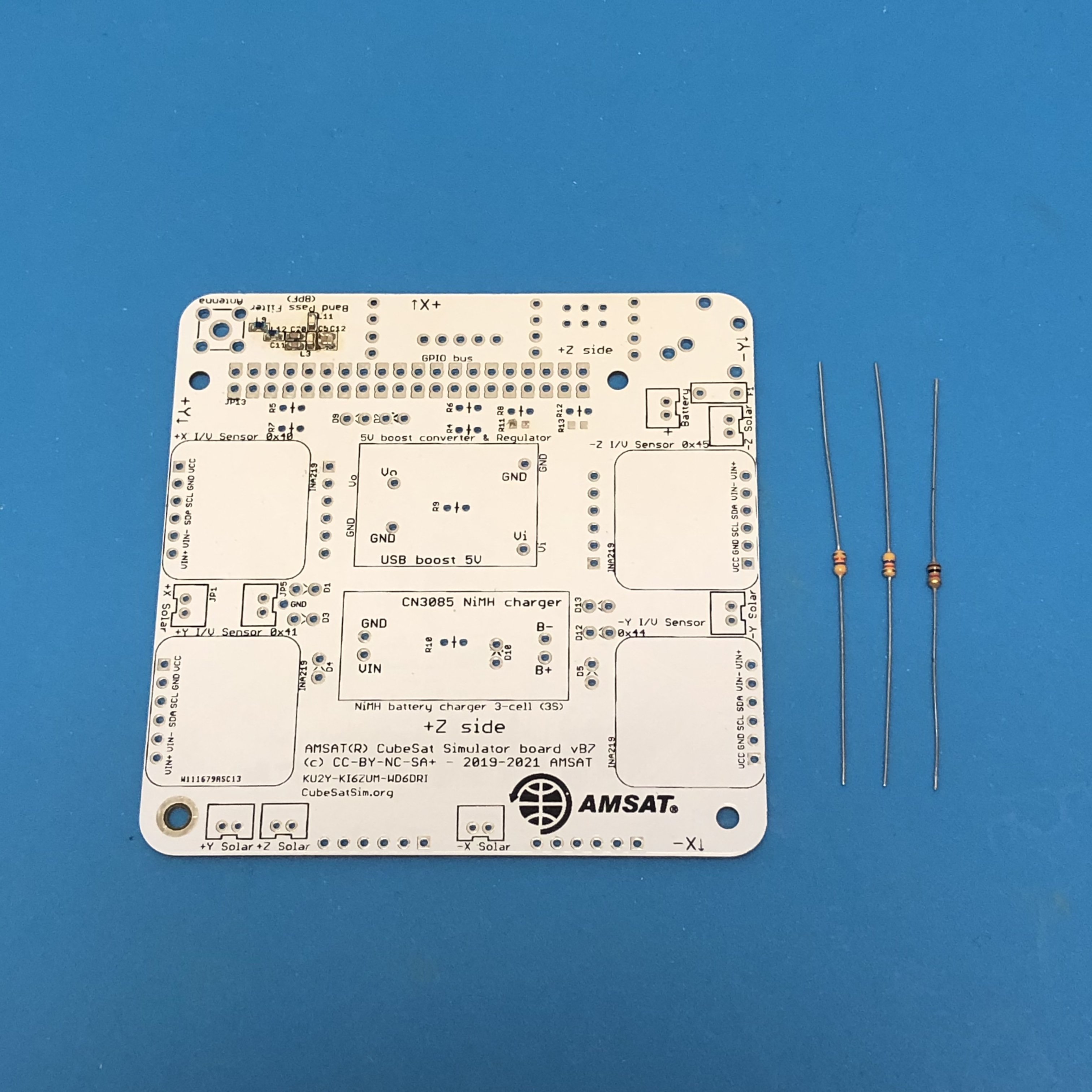
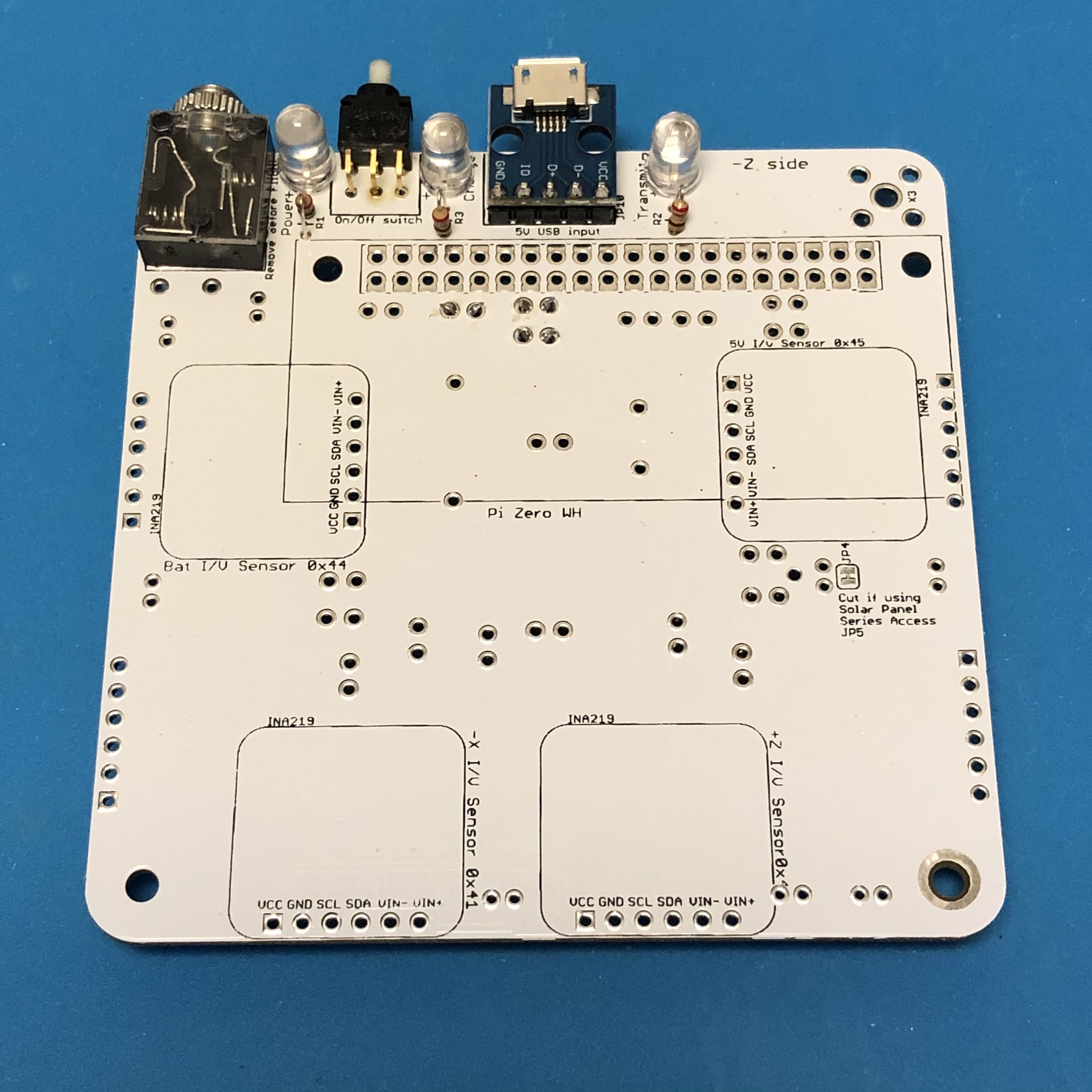
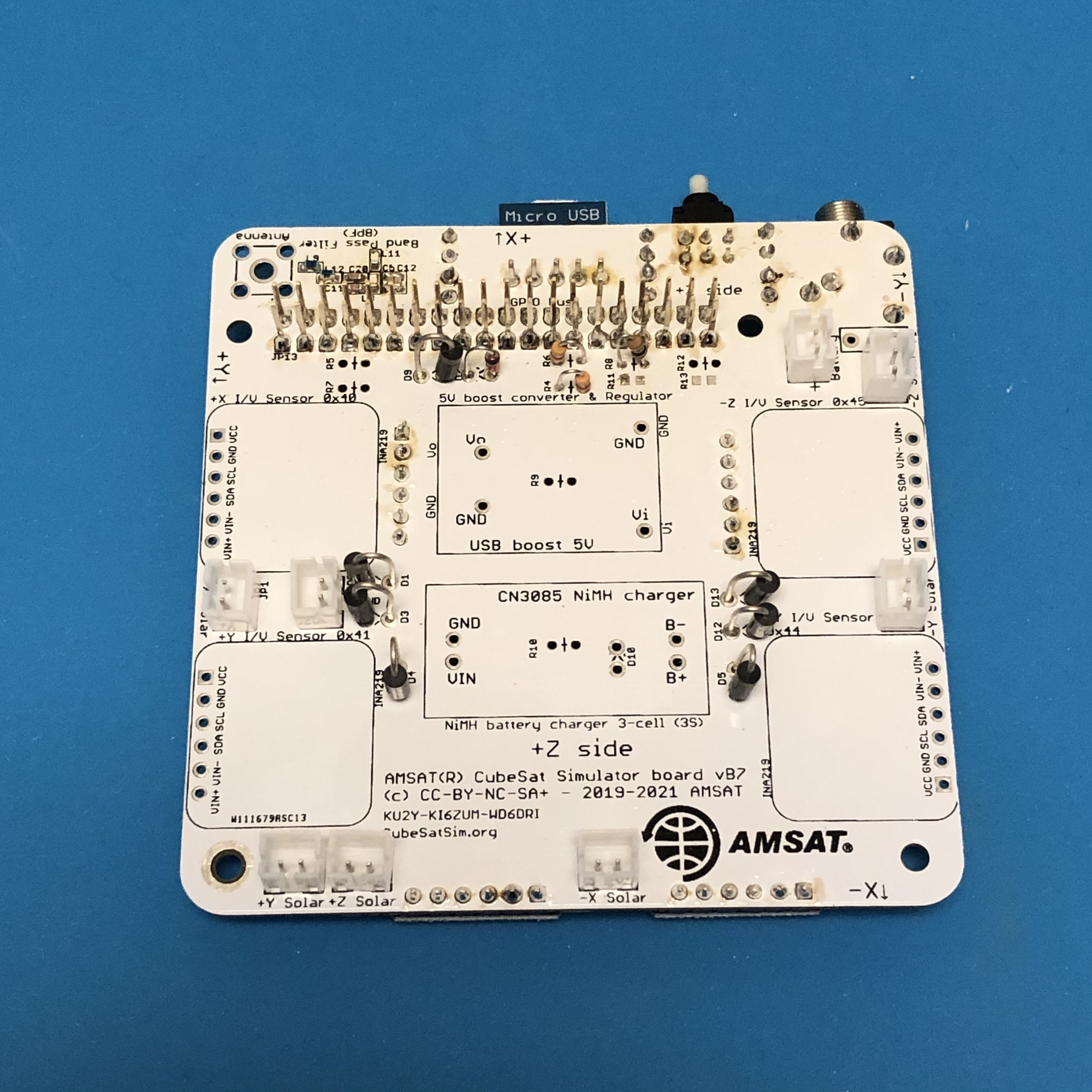
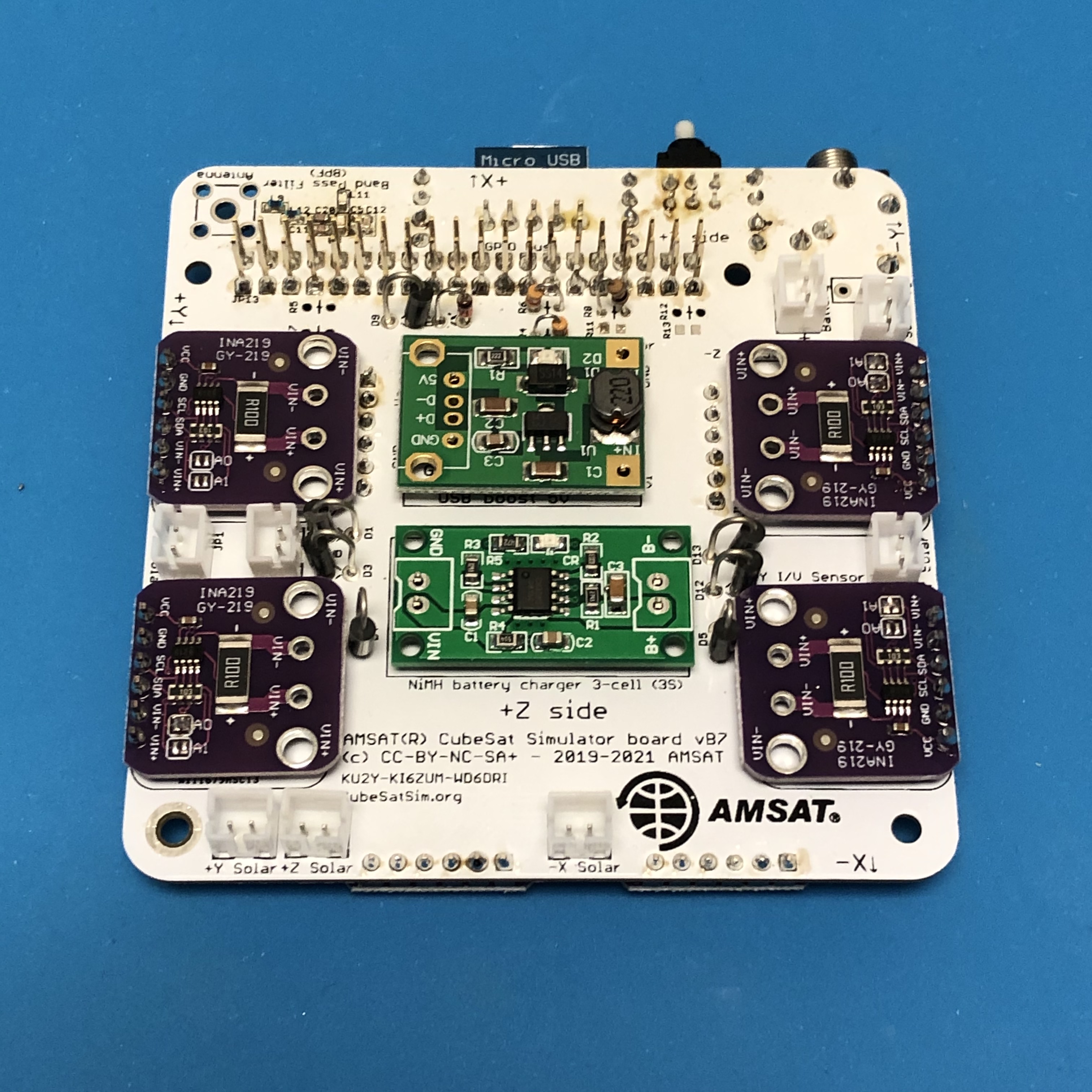
The PCB has components on both sides. This is the top of the PCB, with the AMSAT logo.
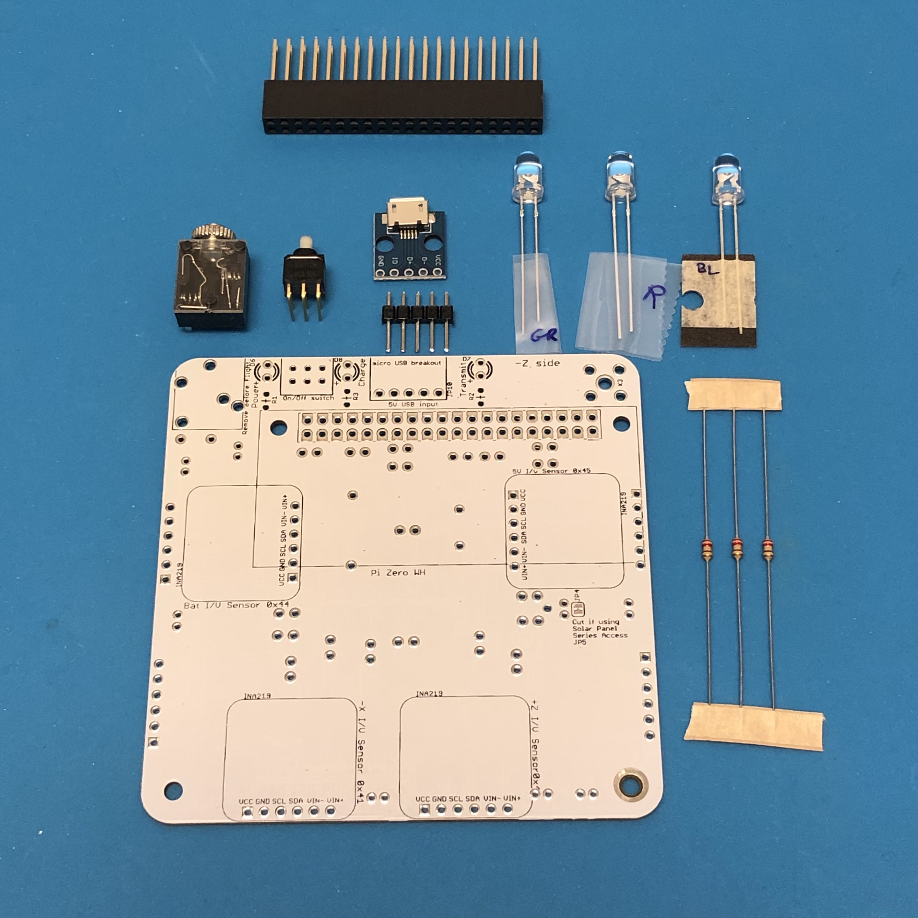
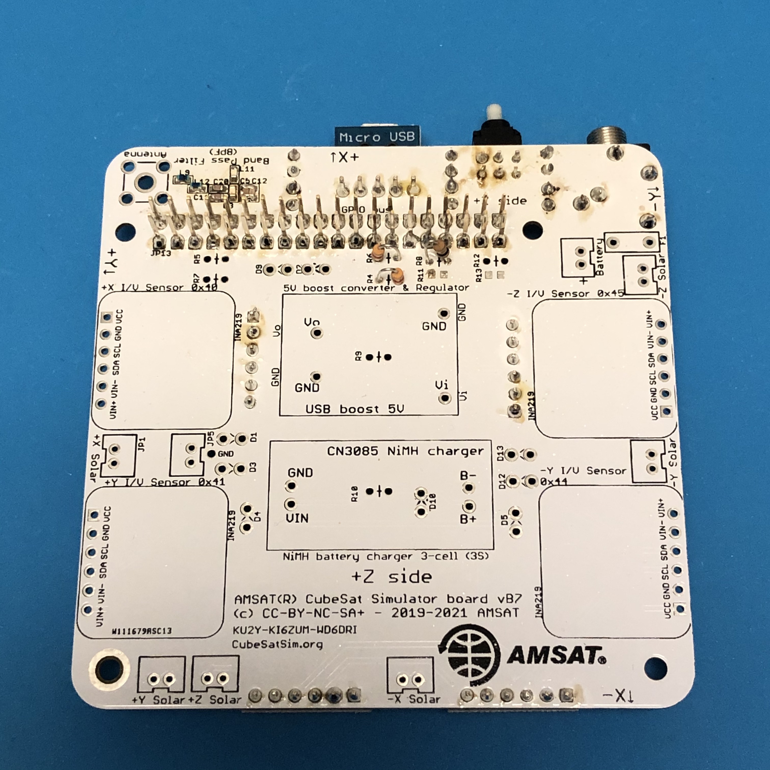
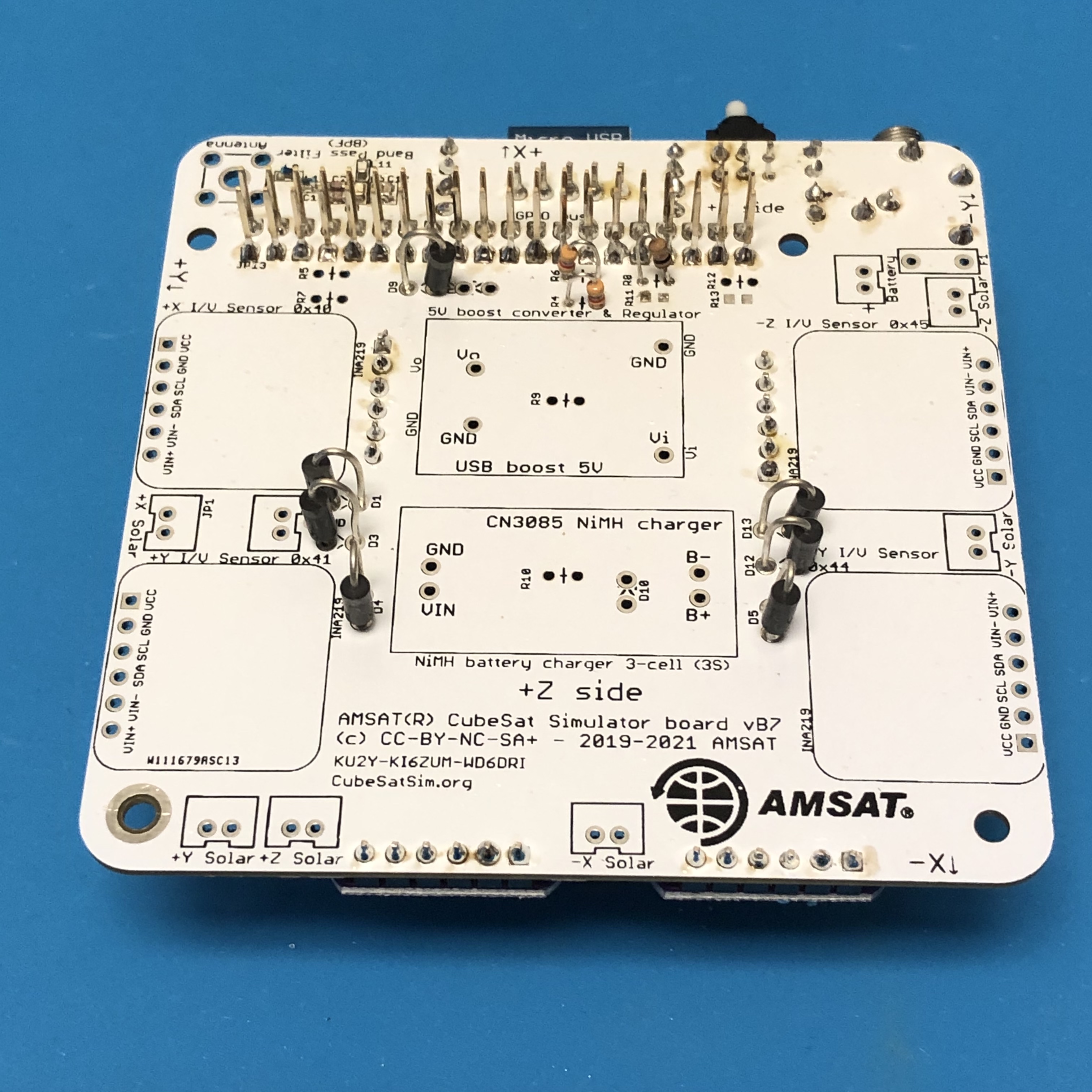
This is the bottom of the PCB.
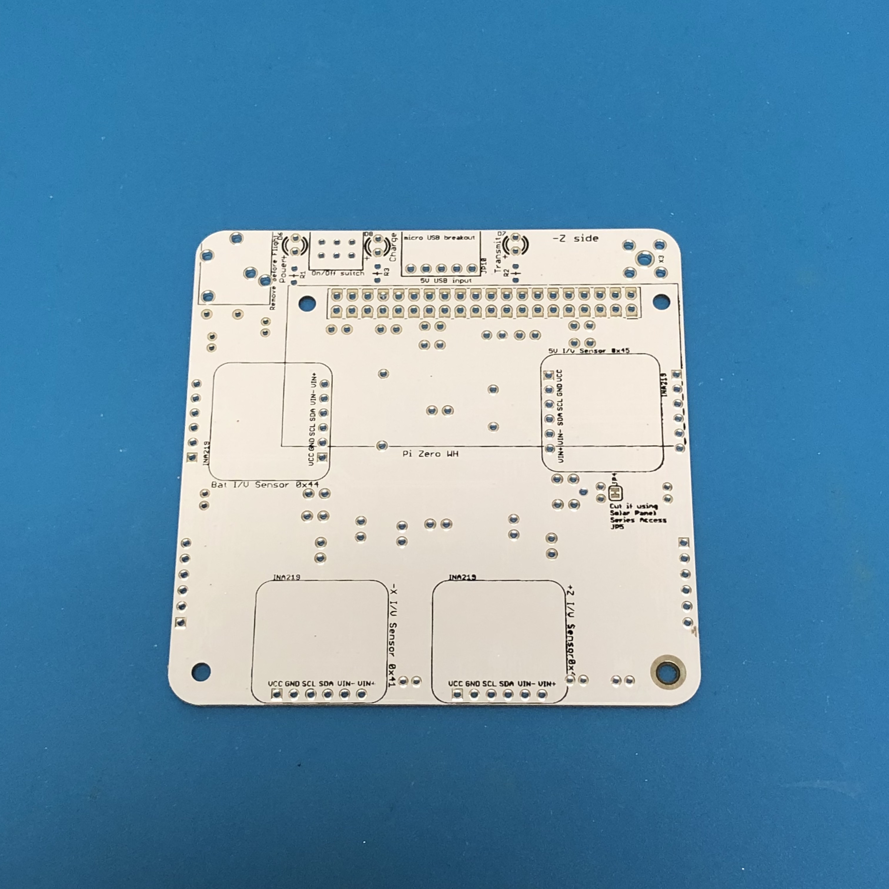
The silkscreen markings indicating which side to mount the parts.
Before any components are soldered onto the board, the Surface Mount Device (SMD) components for the Band Pass Filter (BPF) must be soldered, if they aren't already soldered on. Here is a closeup of the SMD components after they have been mounted:
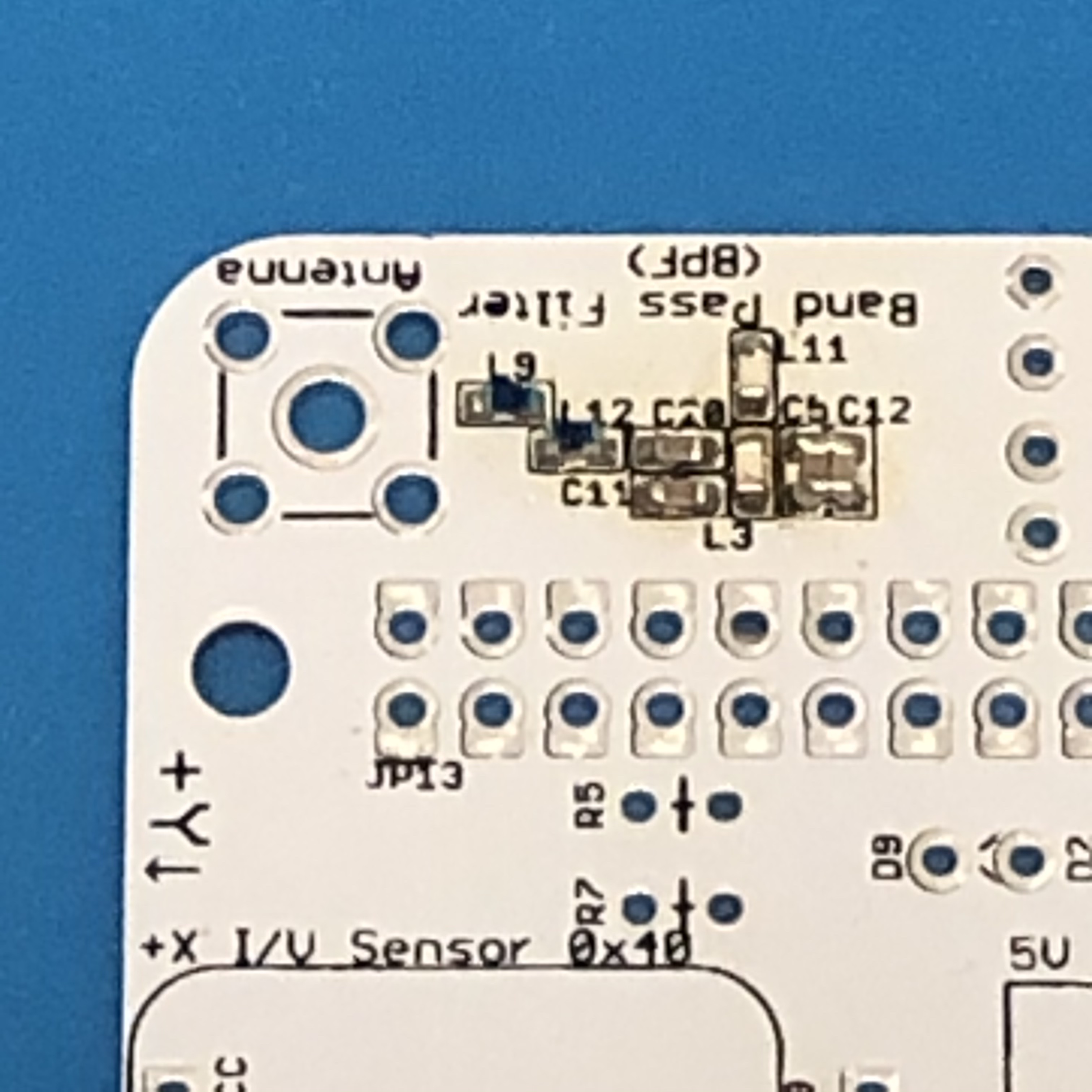
If you don't have the ability to do SMD soldering, you can instead use an external Band Pass Filter with SMA connectors. For example, this BPF works quite well https://www.amazon.com/gp/product/B07R8Y1PM4/
The instructions for the tape measure monopole or dipole are in the Board-Stack instructions.
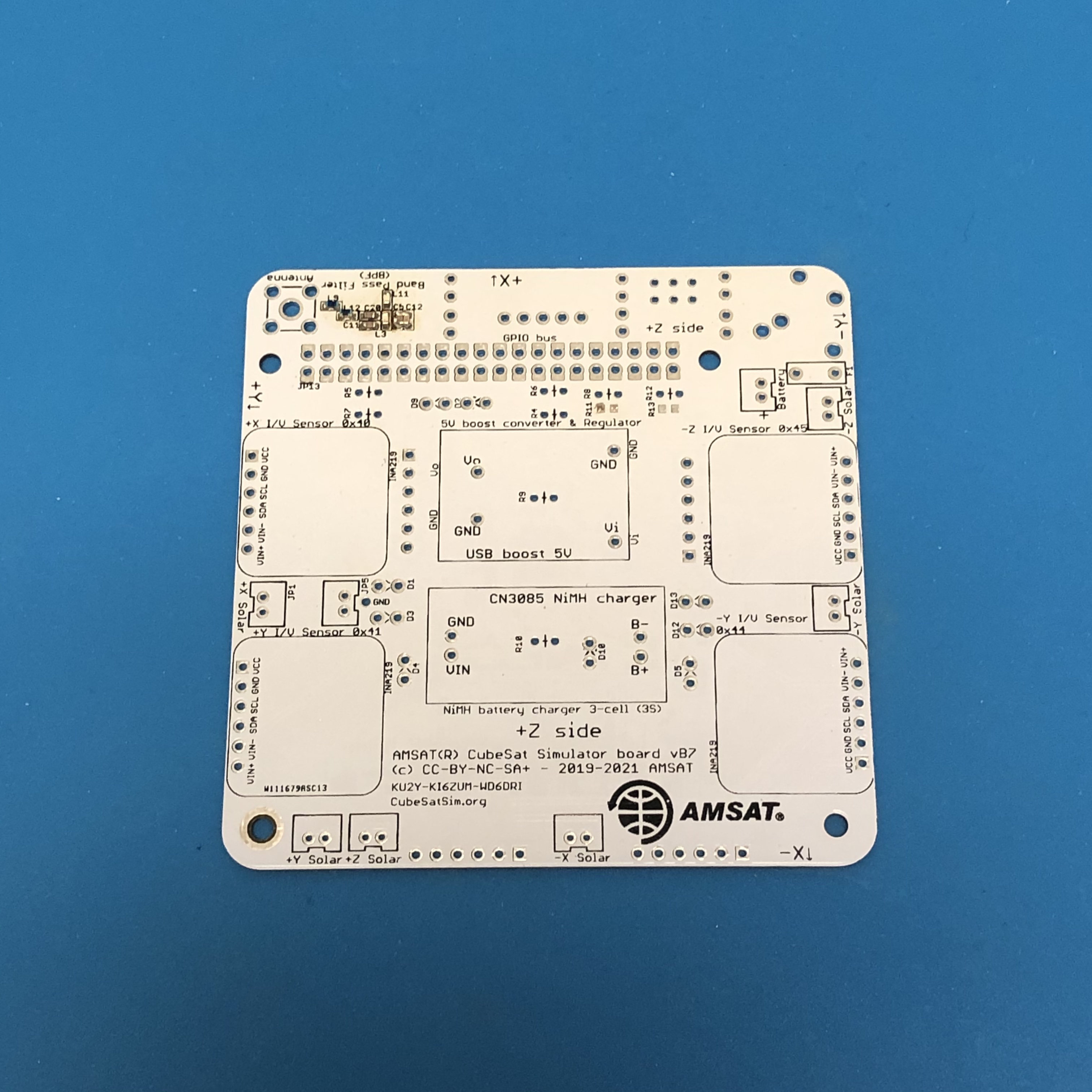
Here's the board with the SMD components soldered in:
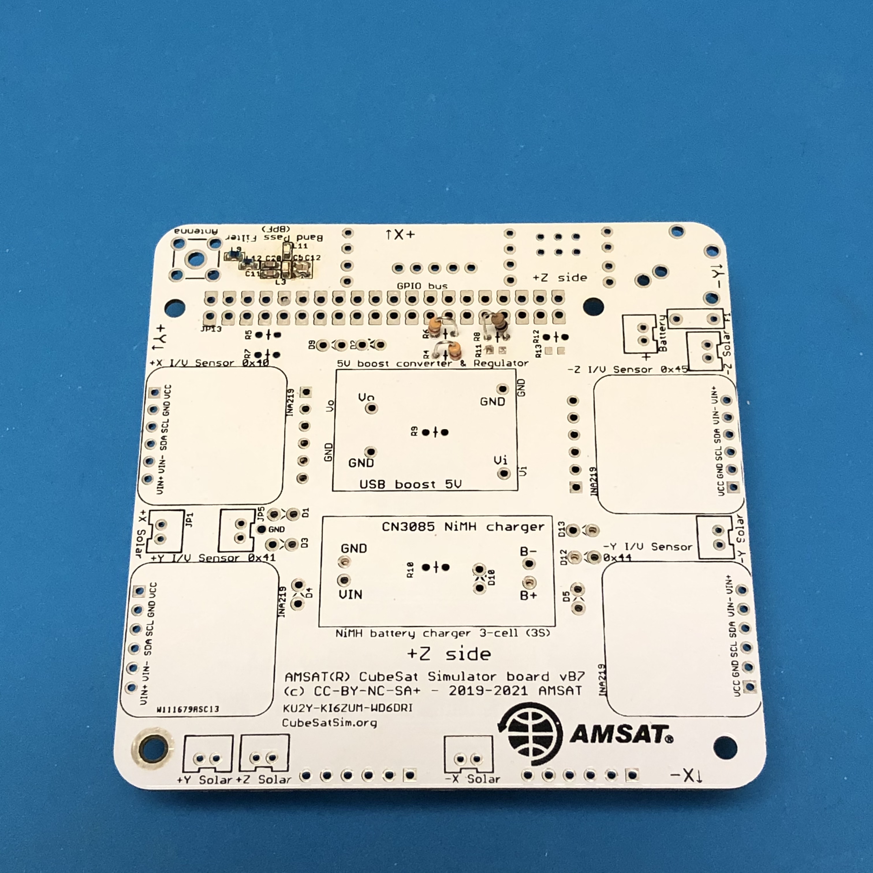
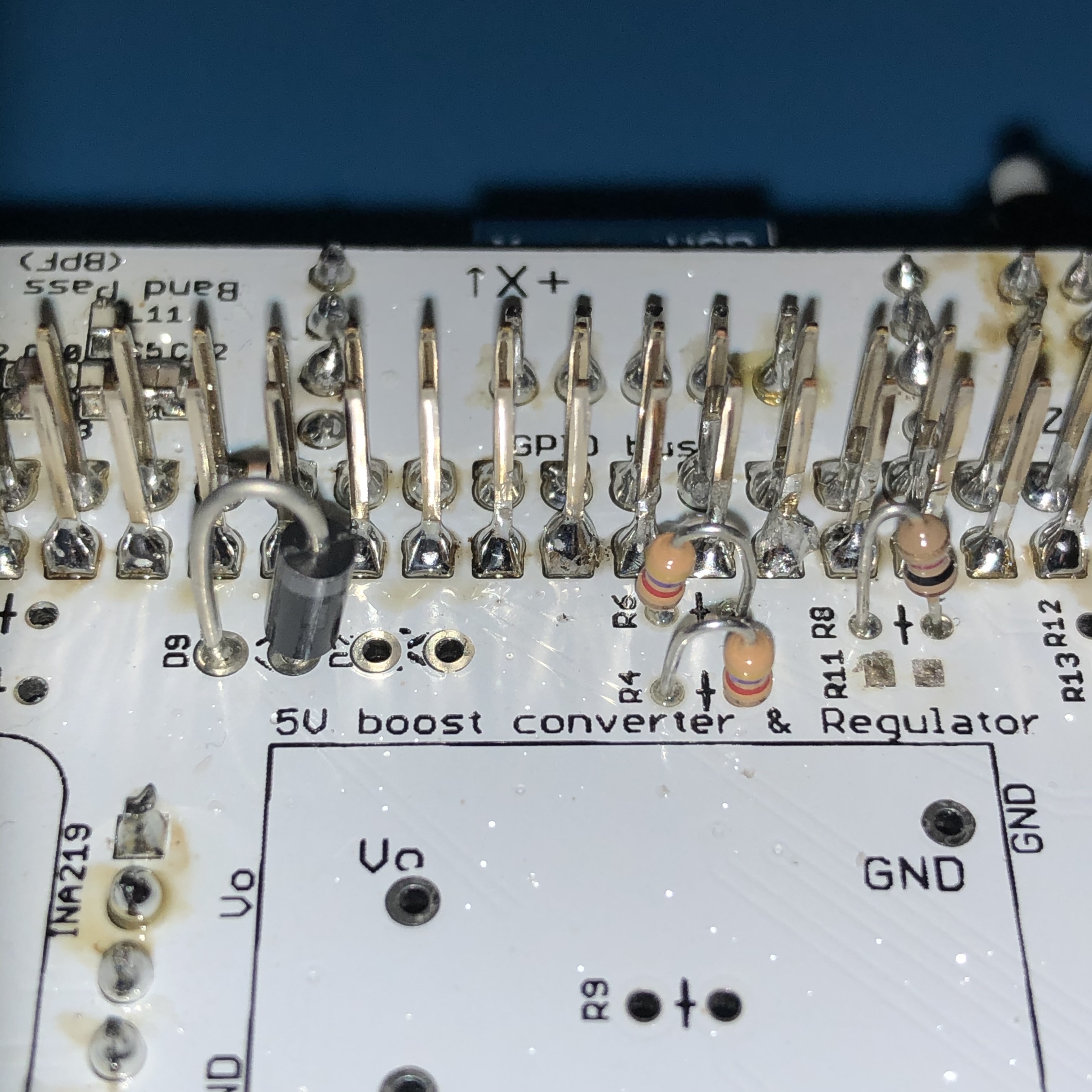
The first step is to solder the resistors R4, R6, and R8 onto the top of the PCB, as shown here.
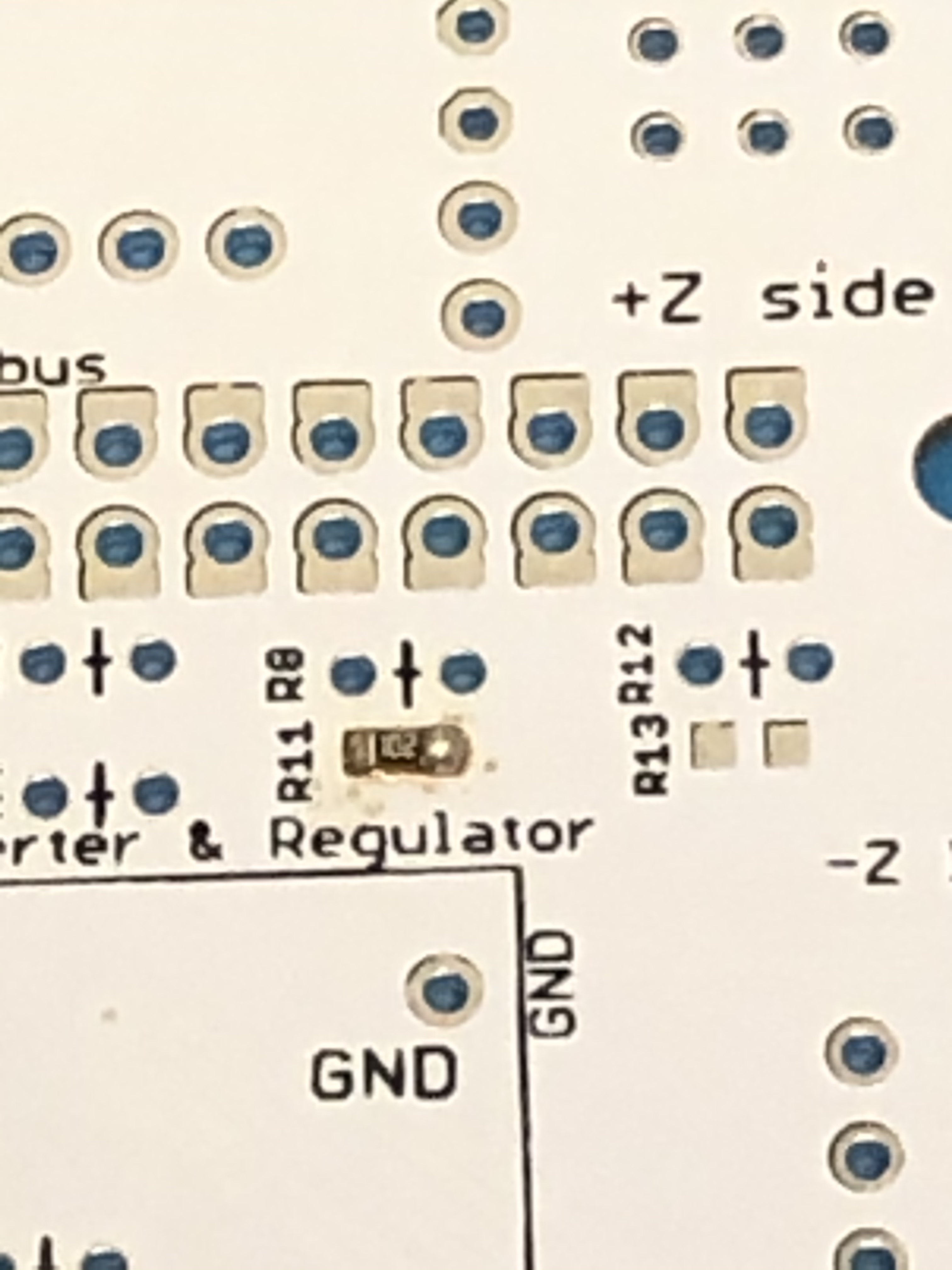
Note that if SMD resistor R11 is installed, R8 should not be installed. Here is R11 installed on the board:
Here is the board after the three resistors are installed:
Note that R5 and R7 should be left unconnected. Next, the pushbutton switch, RBF switch, resistors R1, R2, and R3, the micro USB connector, and then the three LEDs and should be soldered on the bottom of the PCB.
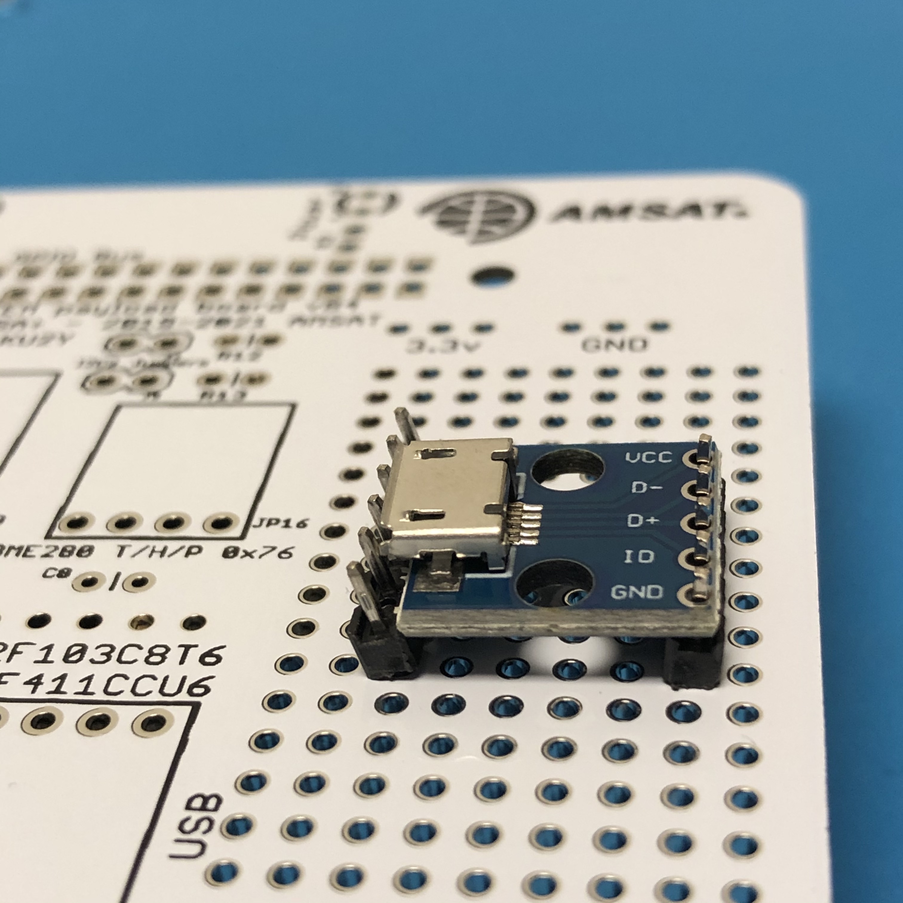
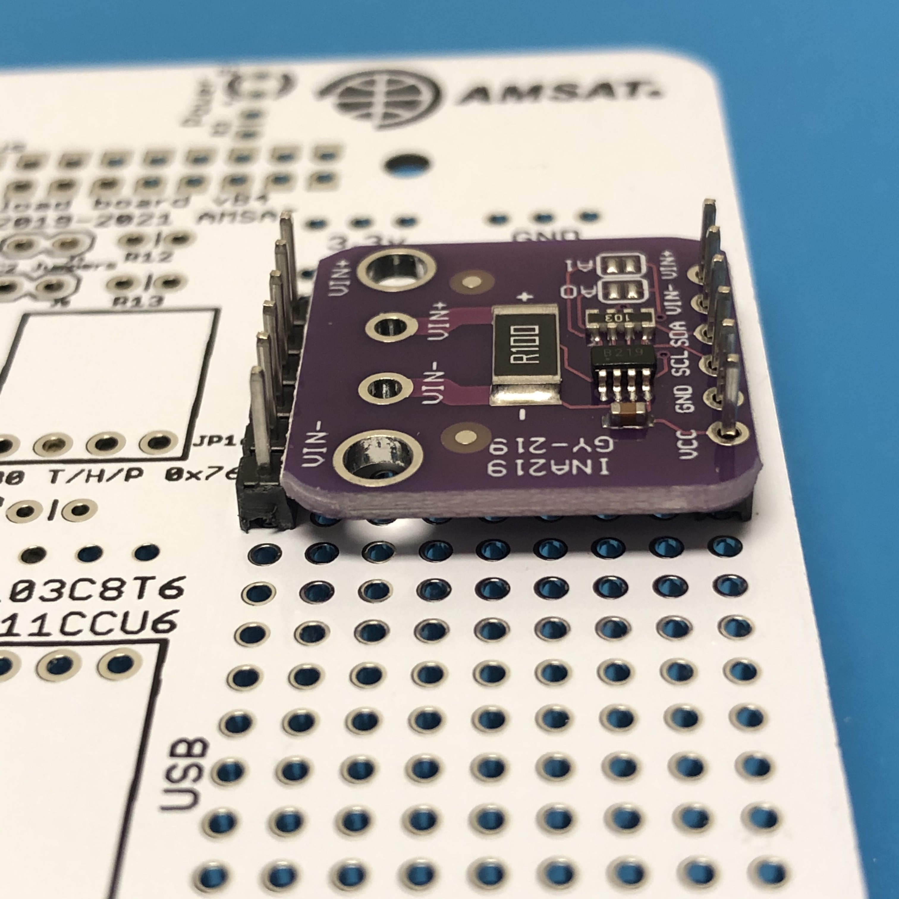
The micro USB board is first soldered to the 1x5 pin header that came with the board. One way to easily solder this straight is to use the STEM Payload board along with a 1x6 pin header from one of the INA219 boards as shown here, allowing the 1x5 pin header to be soldered:
Next, trim the excess length of the 1x5 pin headers
Then, solder the push button switch, the RBF switch (3.5mm audio jack), resistors R1, R2, and R3, the micro USB header, and the three LEDs. If you are using clear lens LEDs, be careful not to mix up the colors! The longer leg on the LED is the '+' and should be away from the edge of the PCB:
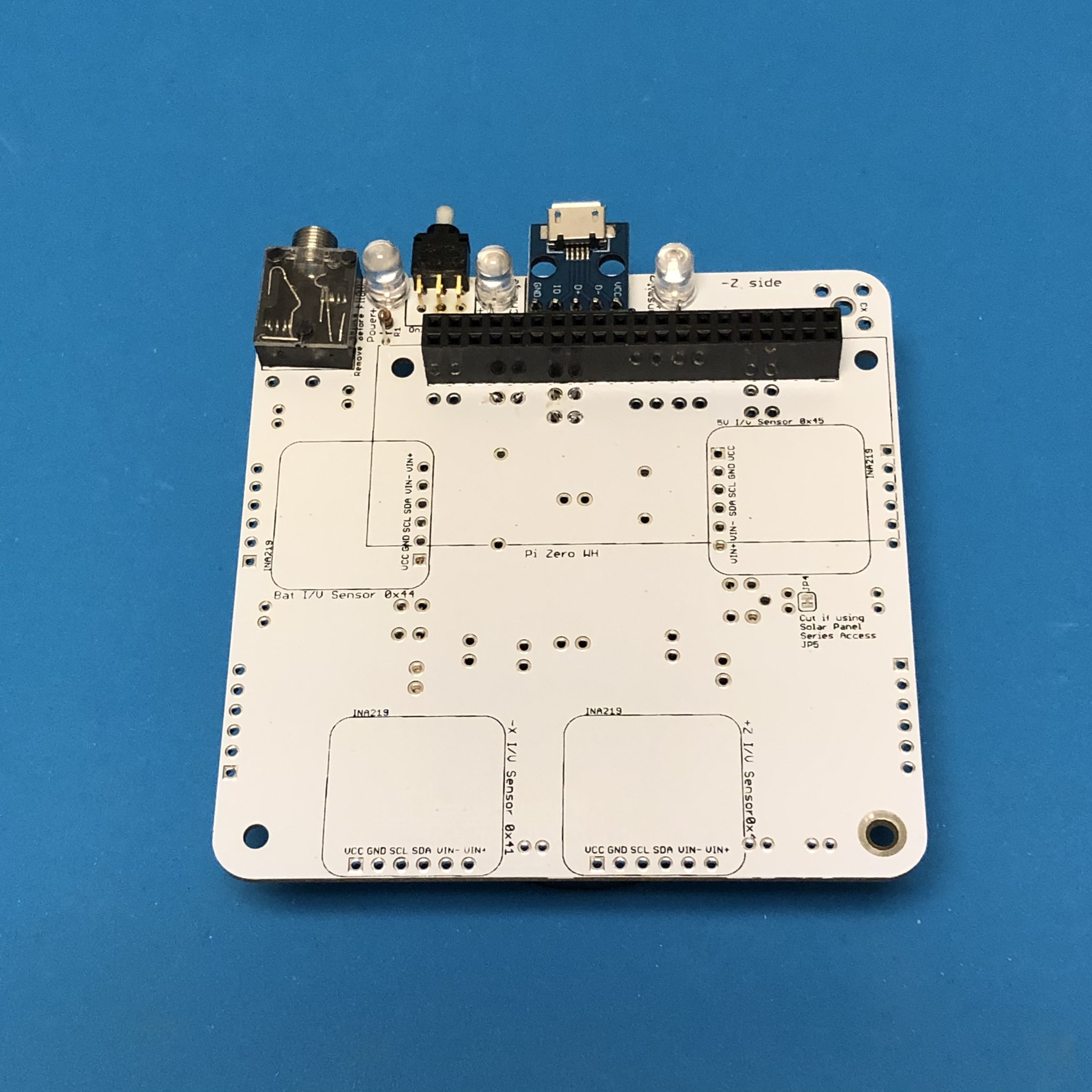
Next, insert the stacking GPIO header on the bottom of the PCB and solder the pins on the top of the PCB. The female side of the connector should be on the bottom of the PCB.
We can now start doing some intermediate tests on the board.
Charge LED Test
For this test, you will need the micro USB charging cable plugged into a computer or a power outlet to supply power. When the charging cable is plugged into the Main board micro USB connector, the red Charge LED will illuminate.
If it doesn't illuminate, check the red LED D8, resistor R3, micro USB connector, or your power cable.
Pi Blink Test
For the rest of these tests, you will need your Raspberry Pi Zero W or Pi Zero, a micro SD card with the CubeSatSim software installed, and the micro USB power cable.
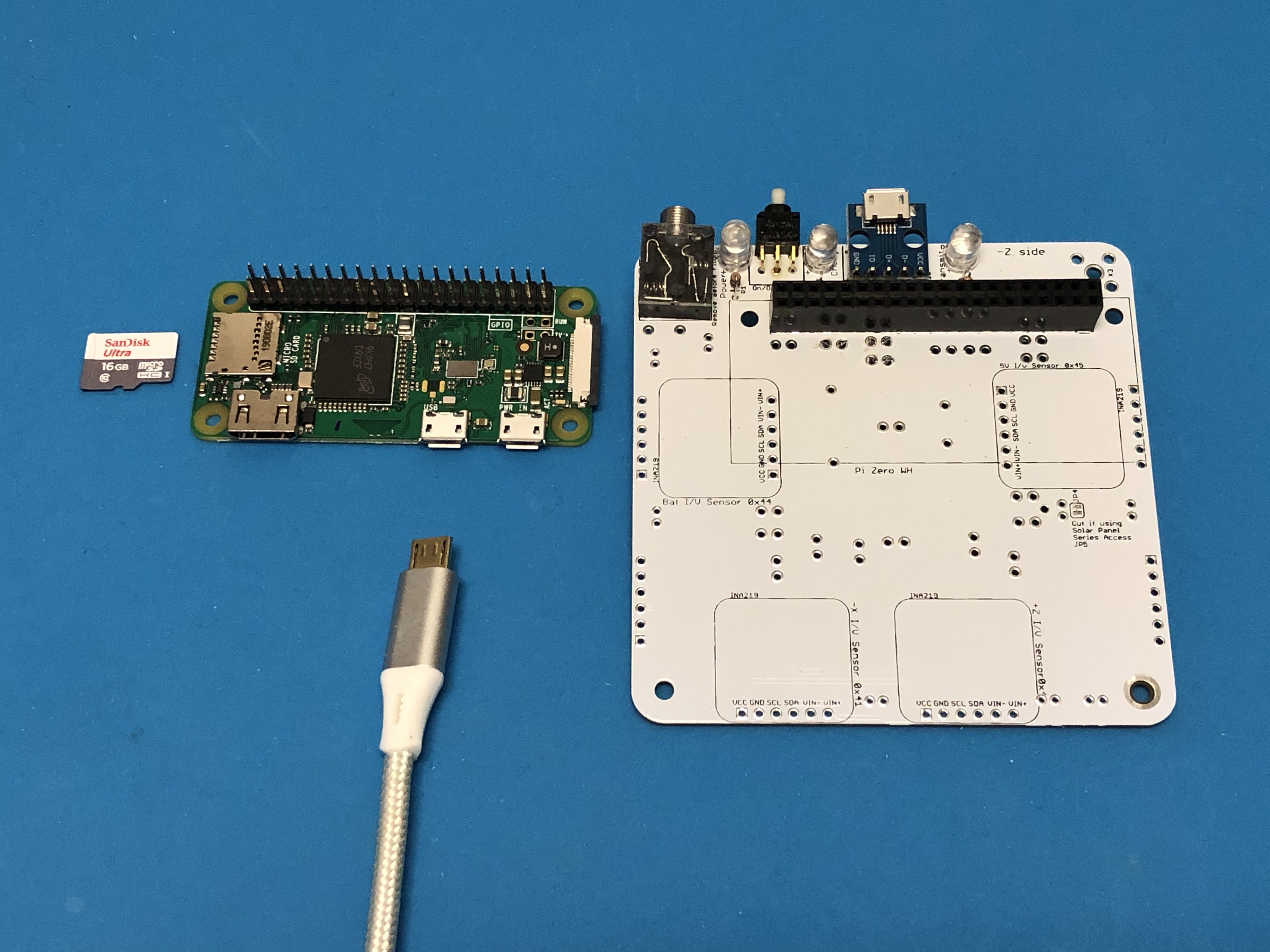
If your Pi Zero W does not have the 2x20 pin header installed, you will need to carefully solder it in.
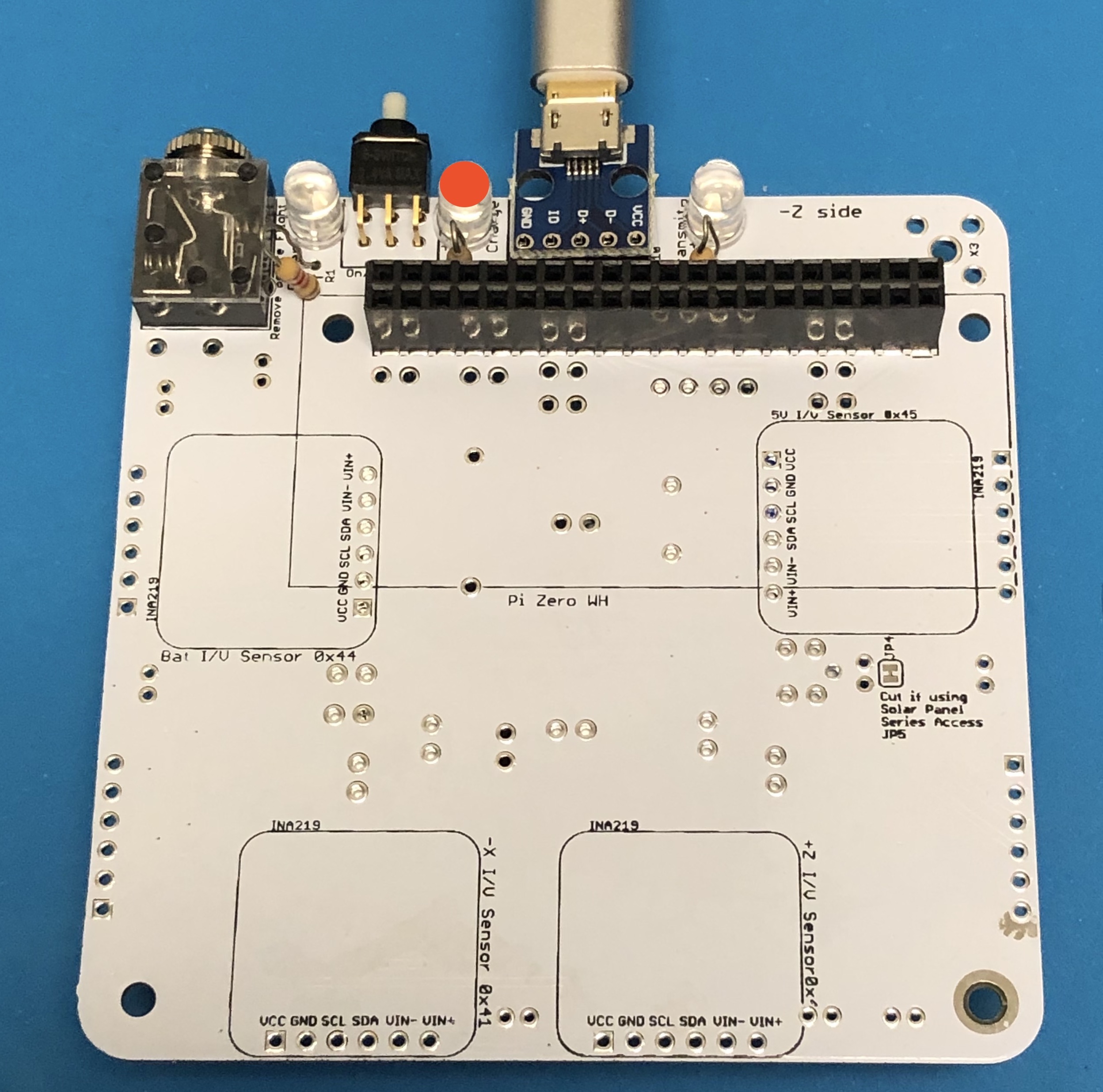
With the Pi plugged into the bottom of the board and powered directly via the Pi micro USB port, the Pi will turn on and the tiny green LED on the Pi will be on or blinking. Note that the LED is on the top of the Pi Zero W board, but you can see it through the lower left mounting hole, as shown here:
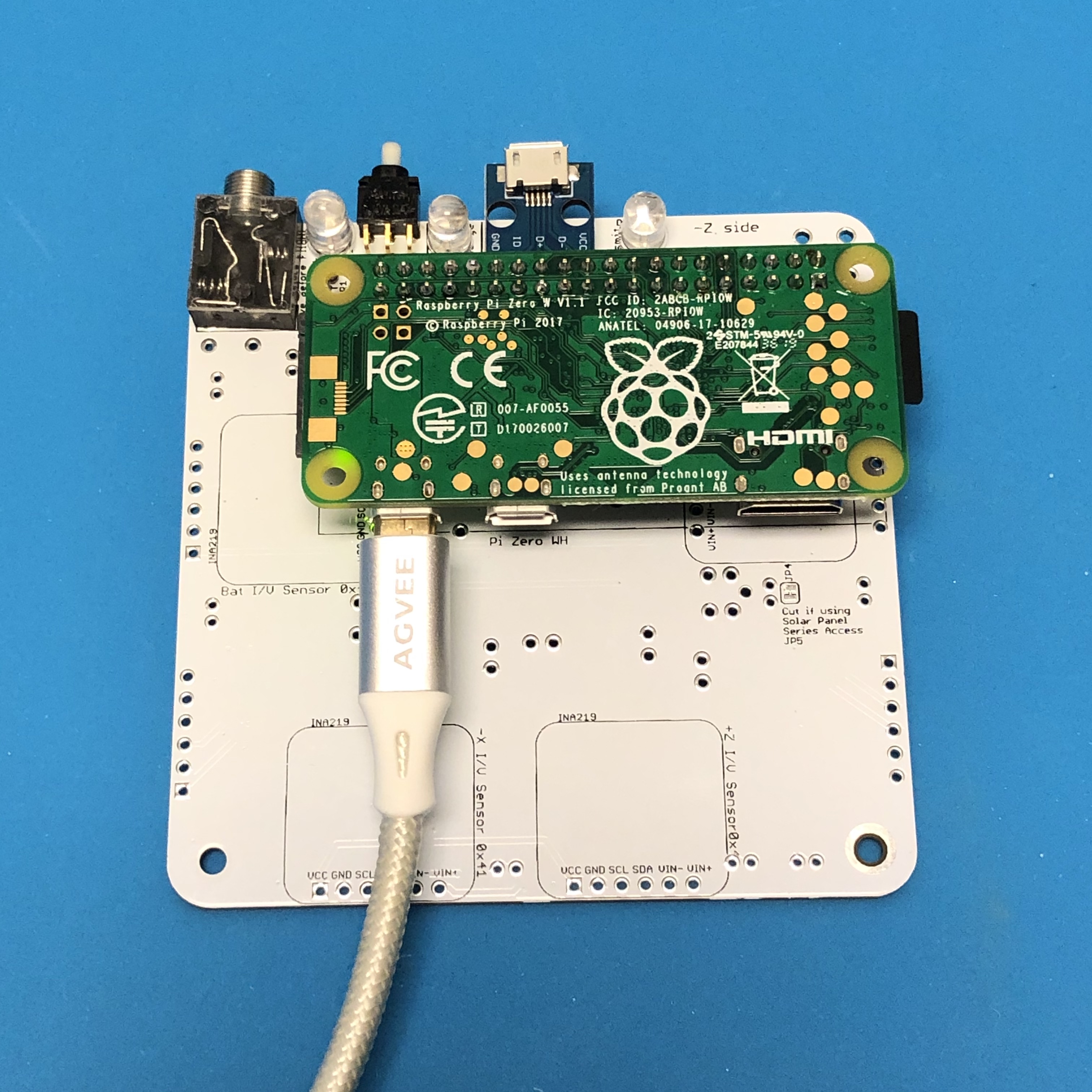
If you don't see this, make sure you have your micro SD card with the CubeSatSim software installed and the micro USB cable providing power.
Power LED Test
With the Pi plugged into the main board and the power cable plugged into the Pi micro USB port, about 30 seconds after booting, the CubeSatSim software will run and turn on the green Power LED.
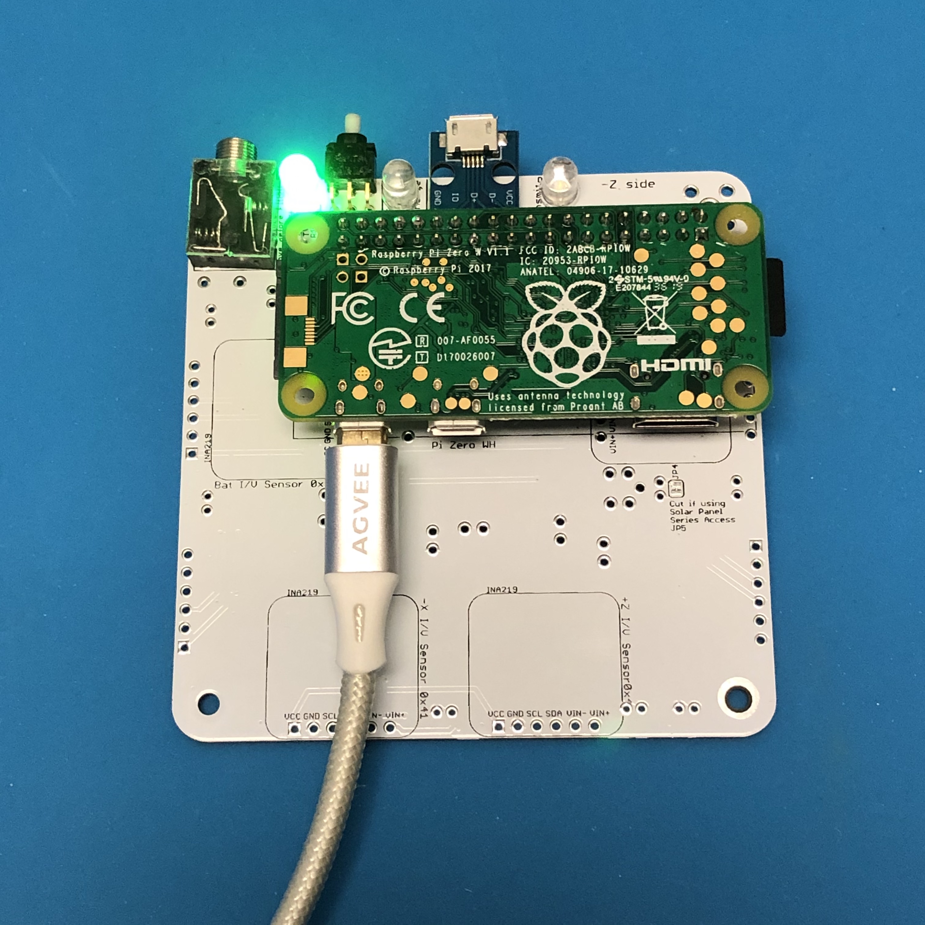
If the LED doesn't illuminate, it might mean there is a problem with the green LED D6 or resistor R1 or that the CubeSatSim software isn't running.
Transmit LED Test
With the Pi plugged into the main board and the power cable plugged into the Pi micro USB port, after booting, the CubeSatSim software will run. When the CubeSatSim is transmitting, the blue Transmit LED will be illuminated, occasionally blinking. This indicates that the CubeSatSim is transmitting.
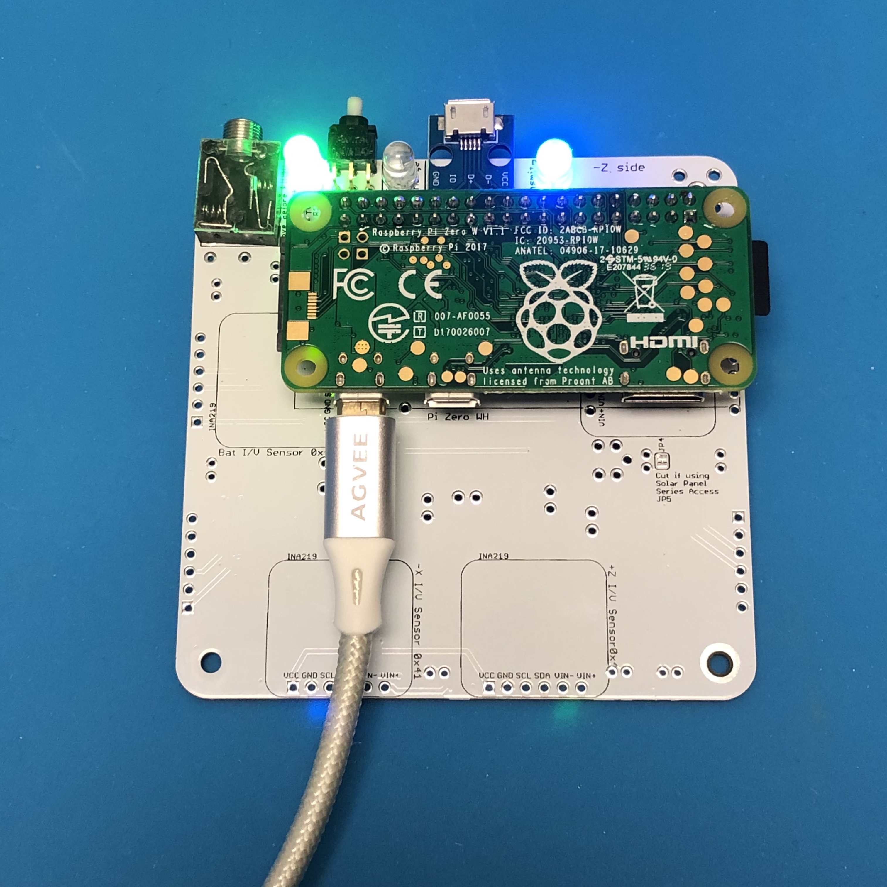
If the blue LED doesn’t illuminate, it might mean there is a problem with the blue LED D6 or resistor R2 or the CubeSatSim software. If it only illuminates once, it might mean that the Band Pass Filter is not detected by the presence of resistor R8 or R11 - check this resistor.
Transmit Test
If the blue LED is illuminated on and off, you can tune your radio or SDR to 434.9 MHz to see and hear an FM signal. Without an antenna, the signal will be weak, but a close by radio will pick it up. If you have your FoxTelem ground station working, you can try to decode frames in FSK mode.
If your blue Transmit LED is illuminated but you don't see a signal, check your antenna on your radio or SDR, and the gain and frequency on your SDR or radio. Or there may be a problem with the CubeSatSim software, in particular the rpitx library.
Push Button Test
With the Pi plugged into the main board and the power cable plugged into the Pi micro USB port, after booting, the CubeSatSim software will run.
- When the push button is pressed and held, the green LED should blink rapidly then stop blinking when the button is released.
- When pressed and immediately released, the Pi should reboot after about 30 seconds.
- When pressed and held until the green LED flashes slowly, the Pi should shutdown (the green Power and blue Transmit LEDs will go out, then the tiny green LED on the Pi will flash rapidly for about 10 seconds then go out). After the Pi is shutdown (no LEDs are on or blinking), you can safely disconnect the micro USB power cable and unplug the Pi from the board to continue the build.
If the green Power LED doesn’t blink, there might be a problem with the push button switch S1 or with the pi-power-button software.
Continuing the Build
If all your test results are "nominal" (expected results), you can continue your build after shutting down the Pi as described in the Power Button Test (by holding the push button until the green LED flashes slowly then releasing) and unplugging the Pi from the board.
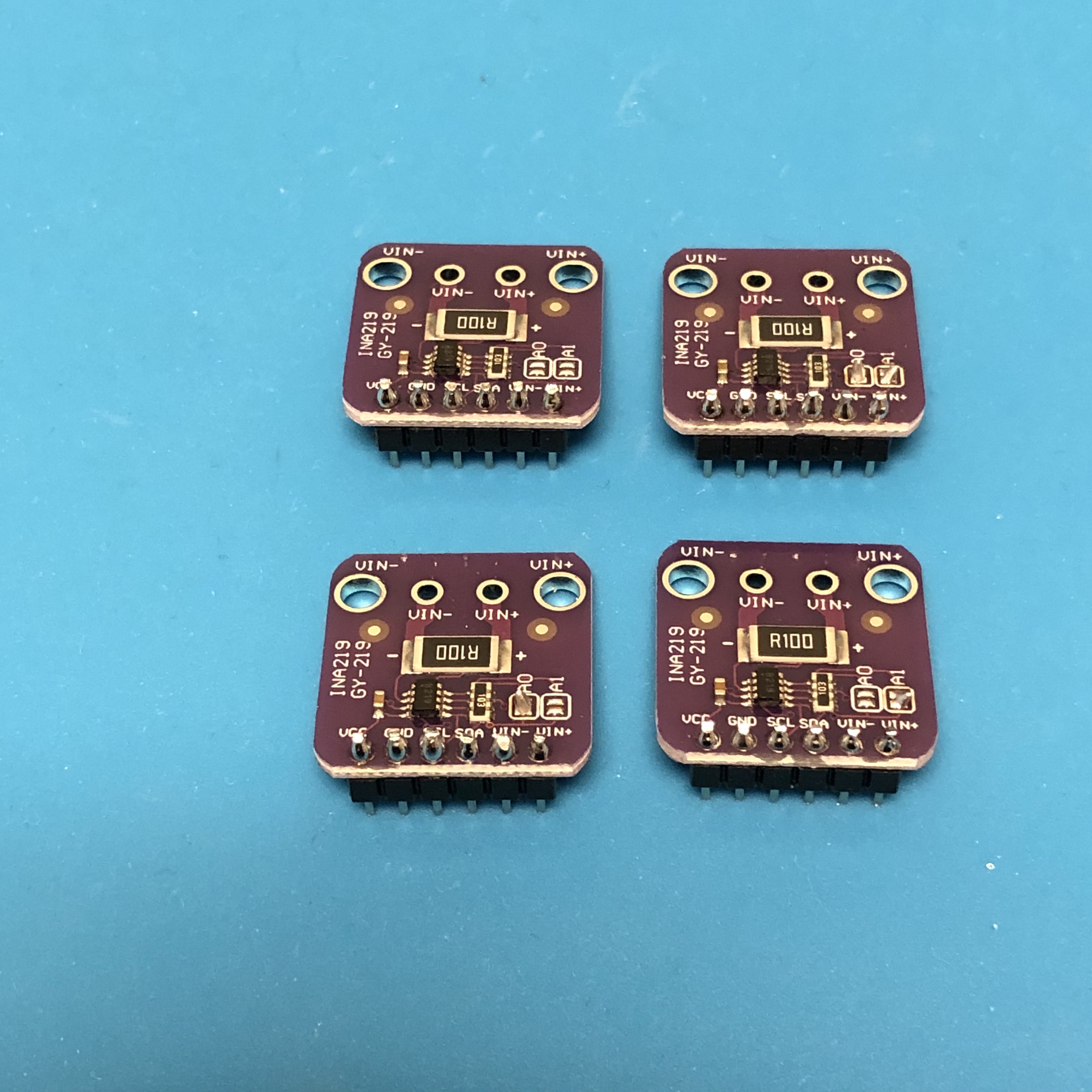
Next, solder the 1x6 pin headers on four of the purple INA219 boards, using the same approach as for the micro USB board:
Trim the excess pin header leads.
Then, set the I2C addresses to all four combinations of solder bridges on the A0 and A1 bridge pads. This will give four I2C addresses as follows:
- 0x40 (no bridges)
- 0x41 (A0 bridged only)
- 0x44 (A1 bridged only)
- 0x45 (A0 and A1 bridged) as shown:
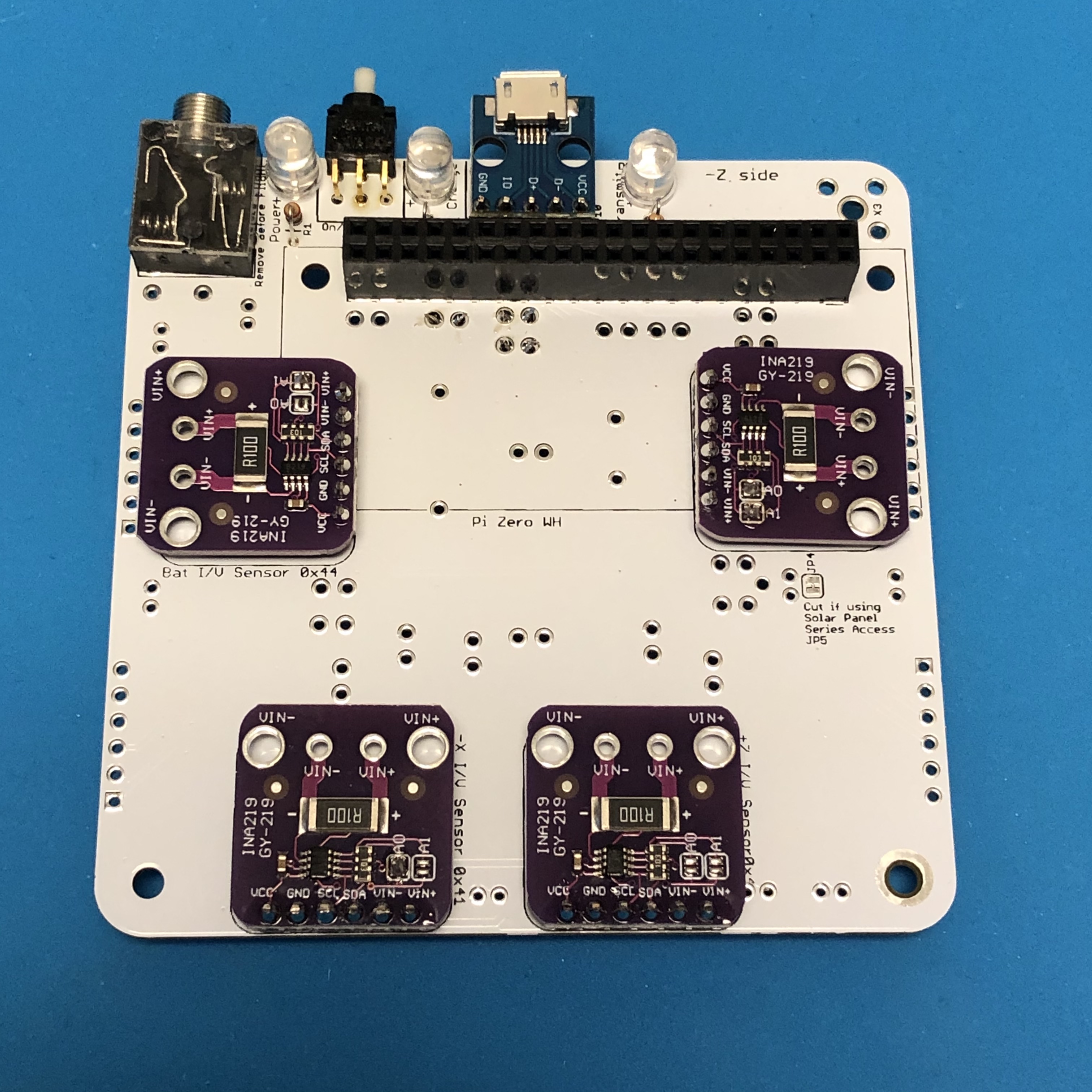
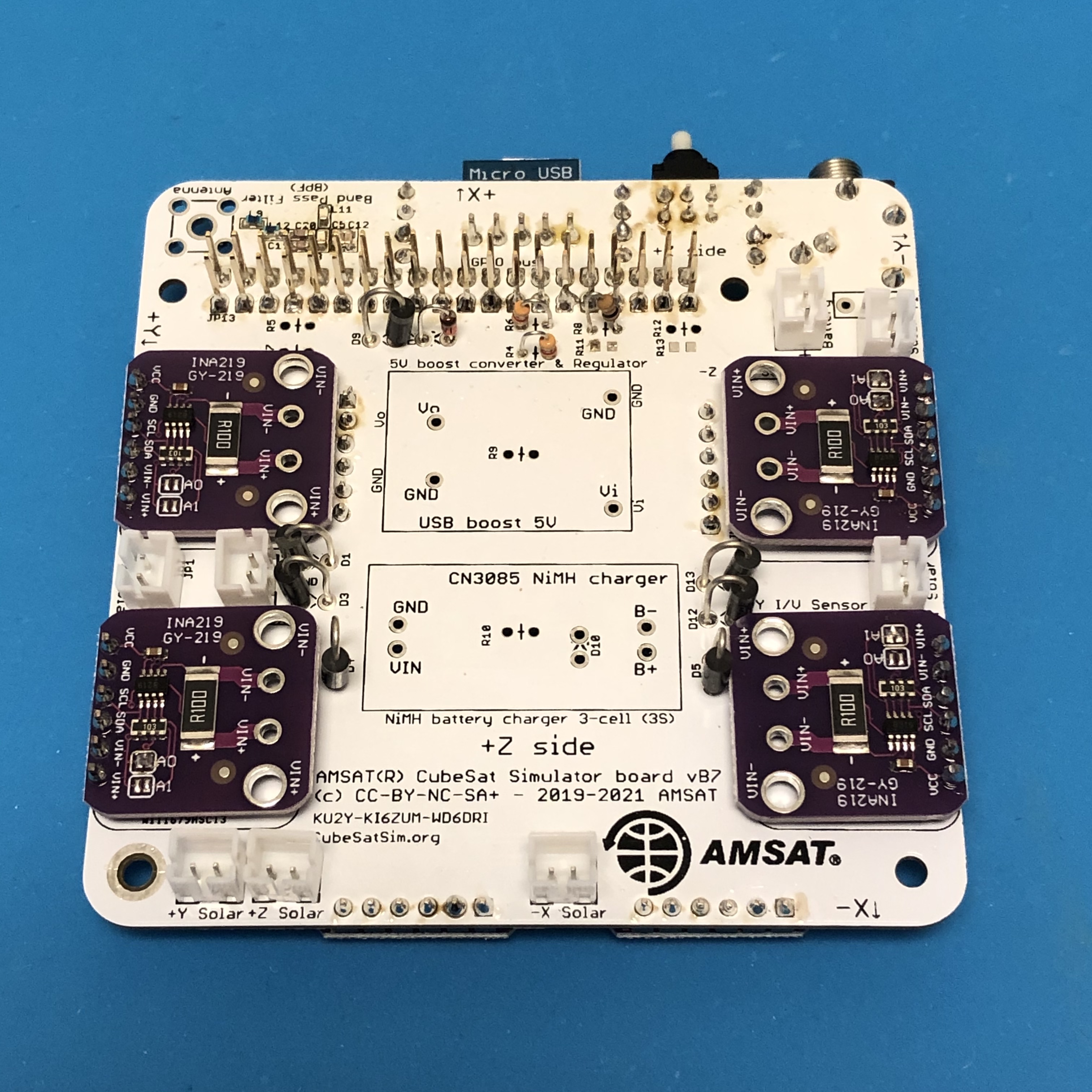
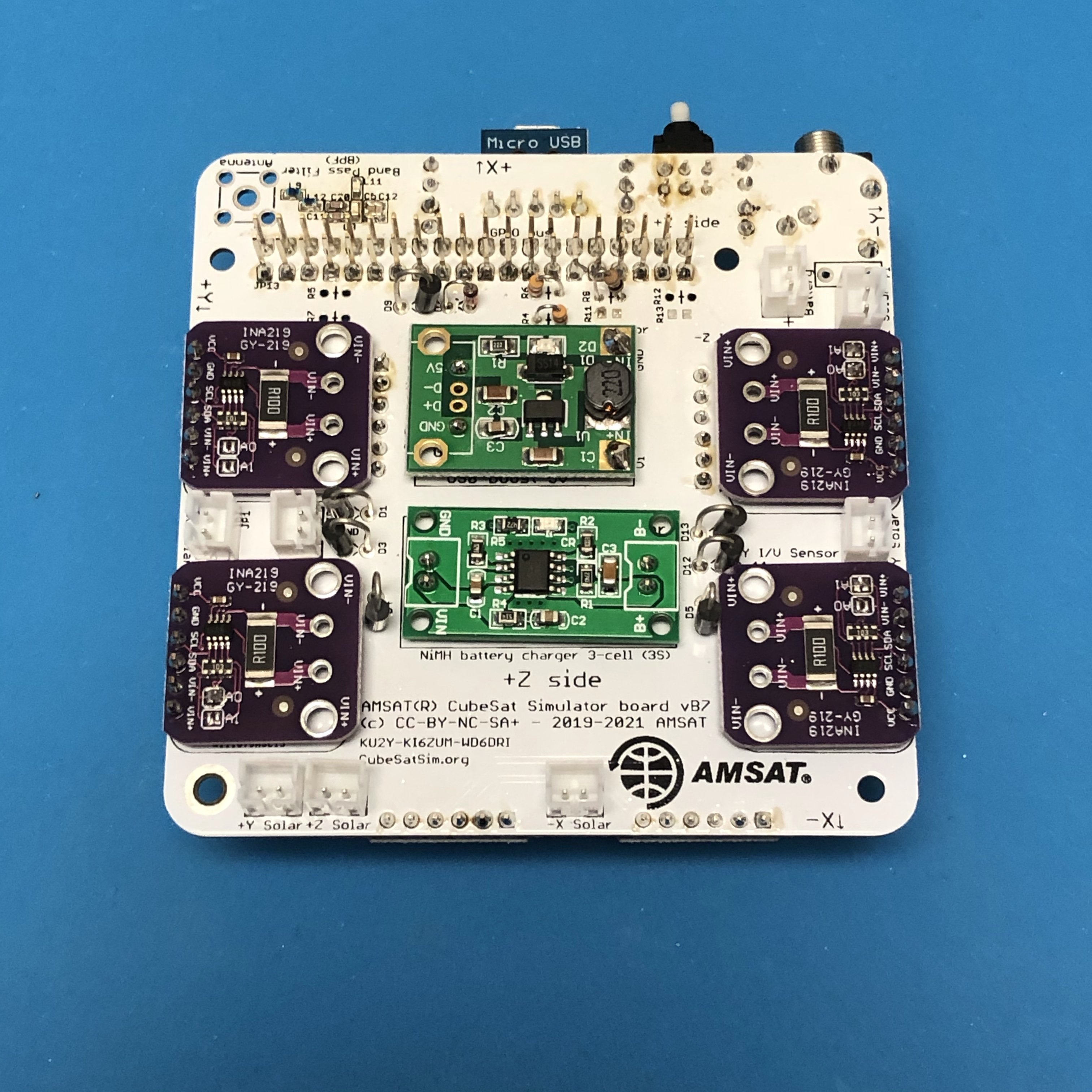
The four INA219 boards should be soldered onto the bottom of the PCB - the correct address for each one is labeled on the PCB:
This completes the bottom of the PCB. The top of the PCB will look like this:
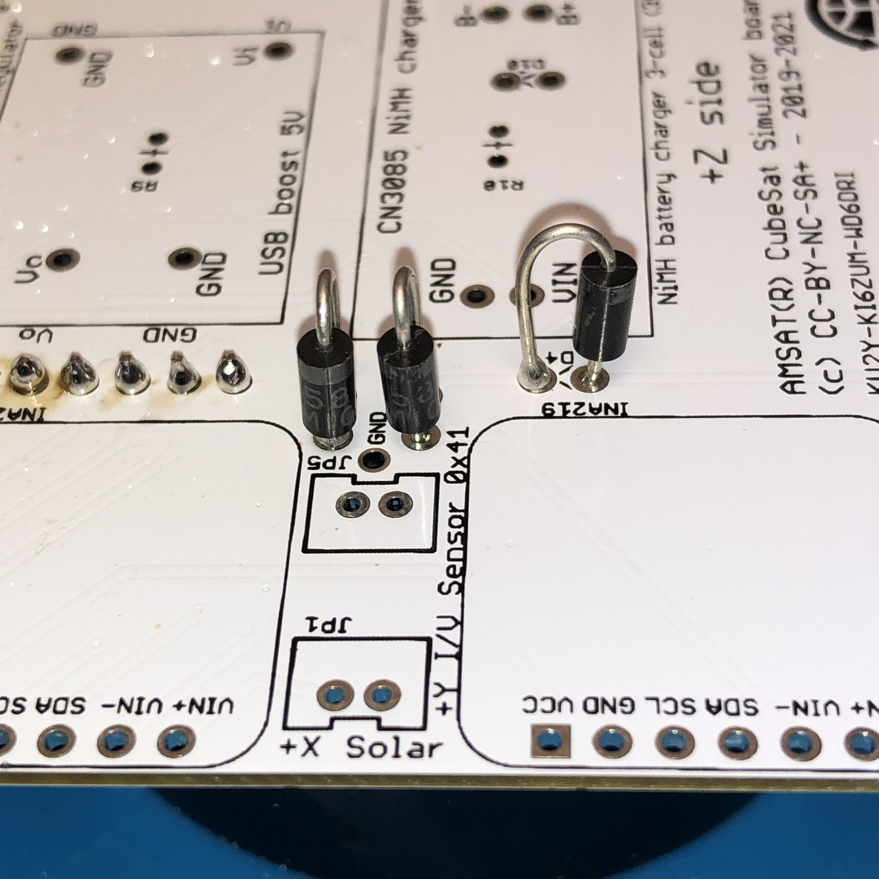
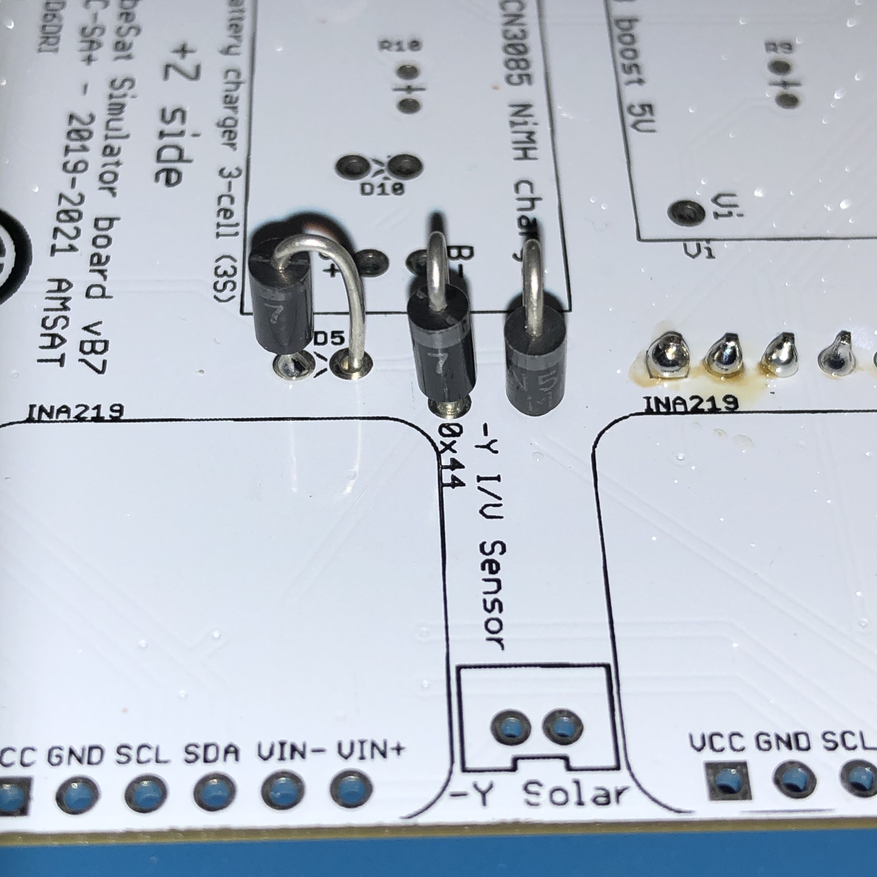
Next, solder the 7 1N517 diodes D1, D3, D4, D5, D9, D12, and D13. Pay attention to the polarity of the diodes, and particularly the placement of D5, D12, and D13 so they do not get in the way of the -Y INA219 board. DO NOT install a diode in D2. With all 7 diodes soldered in, the board looks like:
Here is a closeup showing the correct polarity:
Next, solder the 8 JST 2.0 connectors (note: JP5 is optional and can be left off), and the zener diode D2. The zener diode D2 and the diode D4 from the STEM Payload board look similar, but the zener D2 will have "5V1" written on it (since it is a 5.1V zener diode) while the diode D4 from the STEM Payload board will have "41" and "48" written on it (since it is a 1N4148 diode).
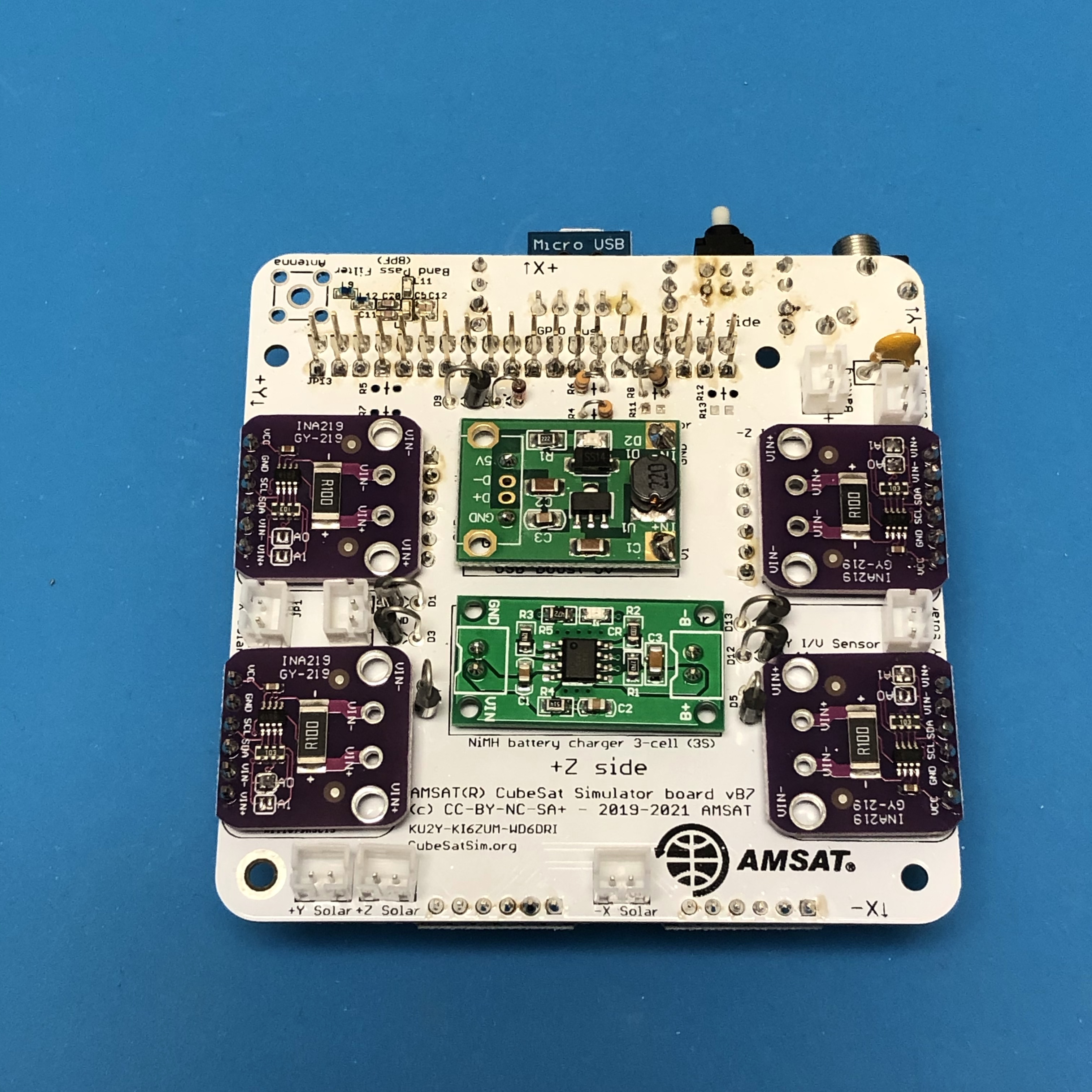
Then, prepare four more INA219s, setting the four possible addresses as before. Solder them in, paying attention to the labels on the PCB:
Next, you should build your Battery Board.
Battery Board Instructions
The Battery Board stacks on top of the main board. Two stacking headers are used to give sufficient spacing for the batteries.
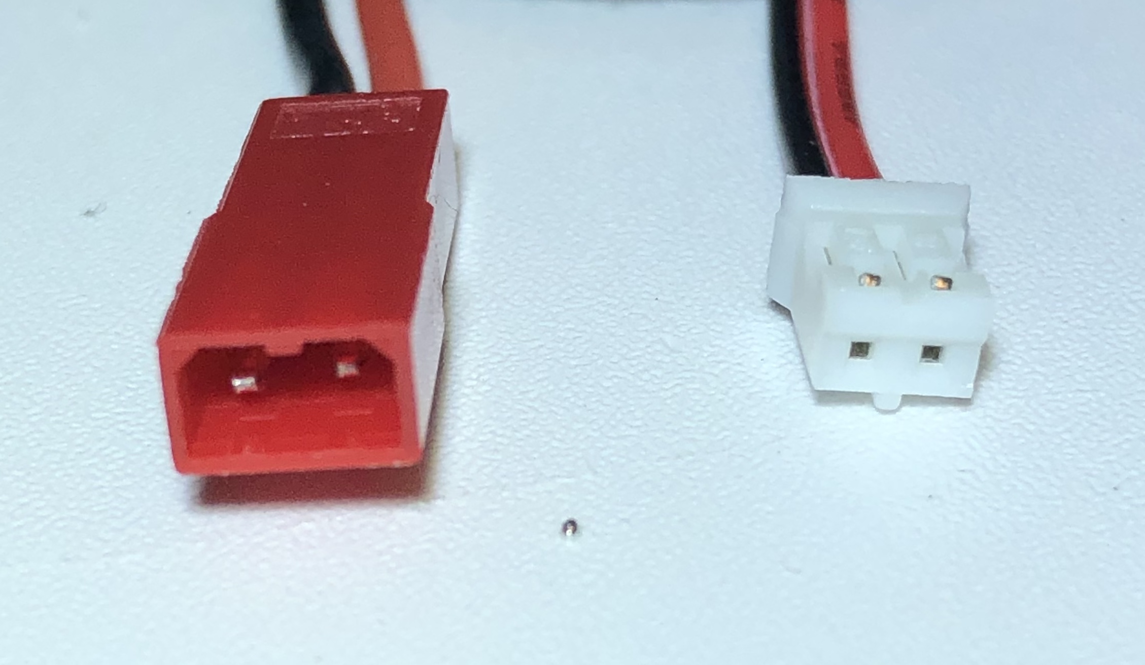
Before using any of your JST connector wires, make sure they have the correct polarity. There is no standard in the industry for red and black, unfortunately, and some suppliers will supply different polarities in different orders. Verify your polarity against this image, and swap if they are reversed:
Either AAA or AA batteries can be used. When doing public demos or events, I would recommend using AA batteries. The CubeSatSim will take over 3 hours to discharge and about the same time to recharge. I'd recommend AAA batteries for classroom demonstrations where you want to see changes in battery voltage right away. The CubeSatSim will discharge in about an hour, and recharge in about the same time.
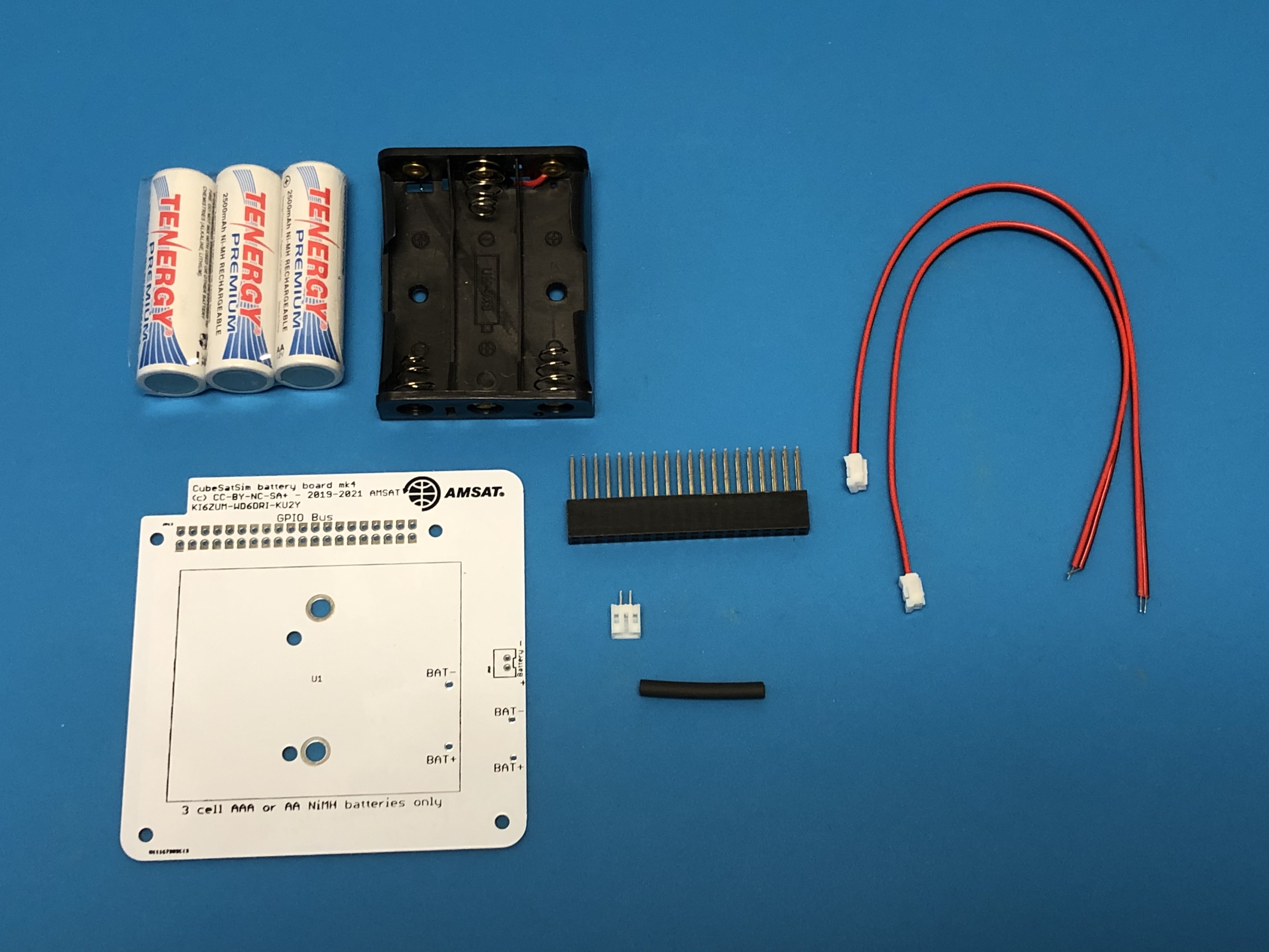
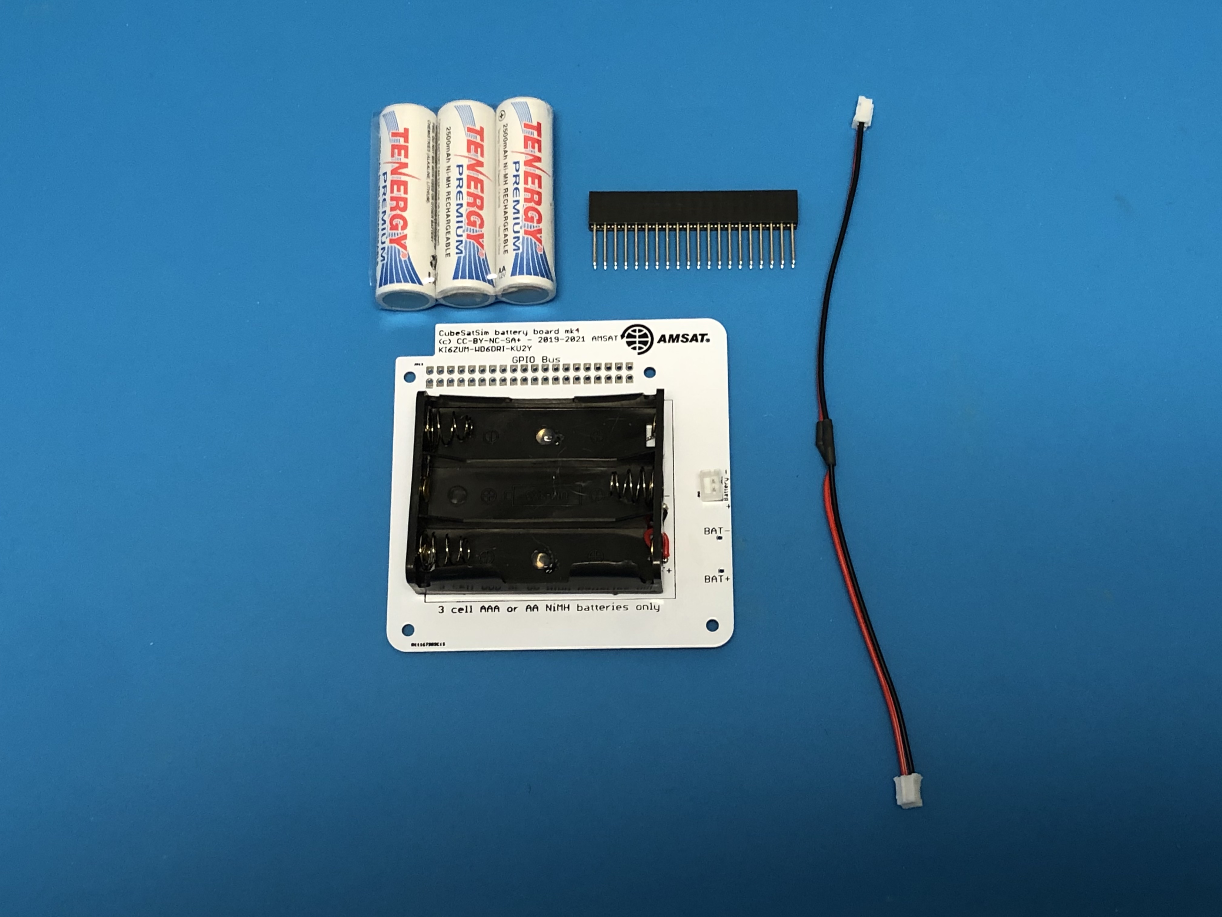
You will need the following parts to make the Battery board: Battery PCB, stacking GPIO header, 3 NiMH cells (either AA or AAA), battery holder (either AA or AAA), two JST 2.0 cables, a JST 2.0 connector, and a piece of heat shrink tube, as shown here:
First make up the micro JST cable (4"-6" long) by soldering the red to red and black to black of the JST 2.0 cables, and covering the connections with the cut in half heat shrink tubing. Next, insert the battery holder and JST 2.0 connector onto the top of the PCB and solder:
Then insert the stacking GPIO header on the bottom of the PCB and solder. Note that there is no connection on any GPIO header pins to this board. If you just solder two pins on either side (4 pins in total), that will anchor it in place. Soldering all 40 pins doesn't do anything useful.
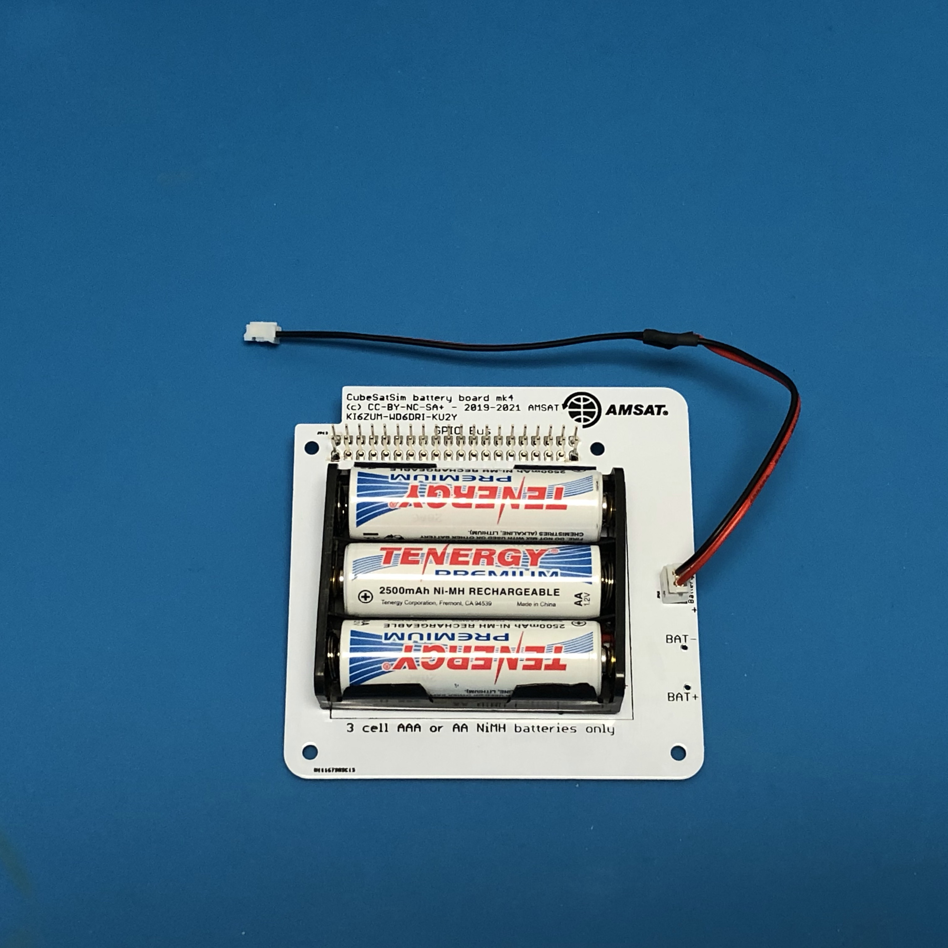
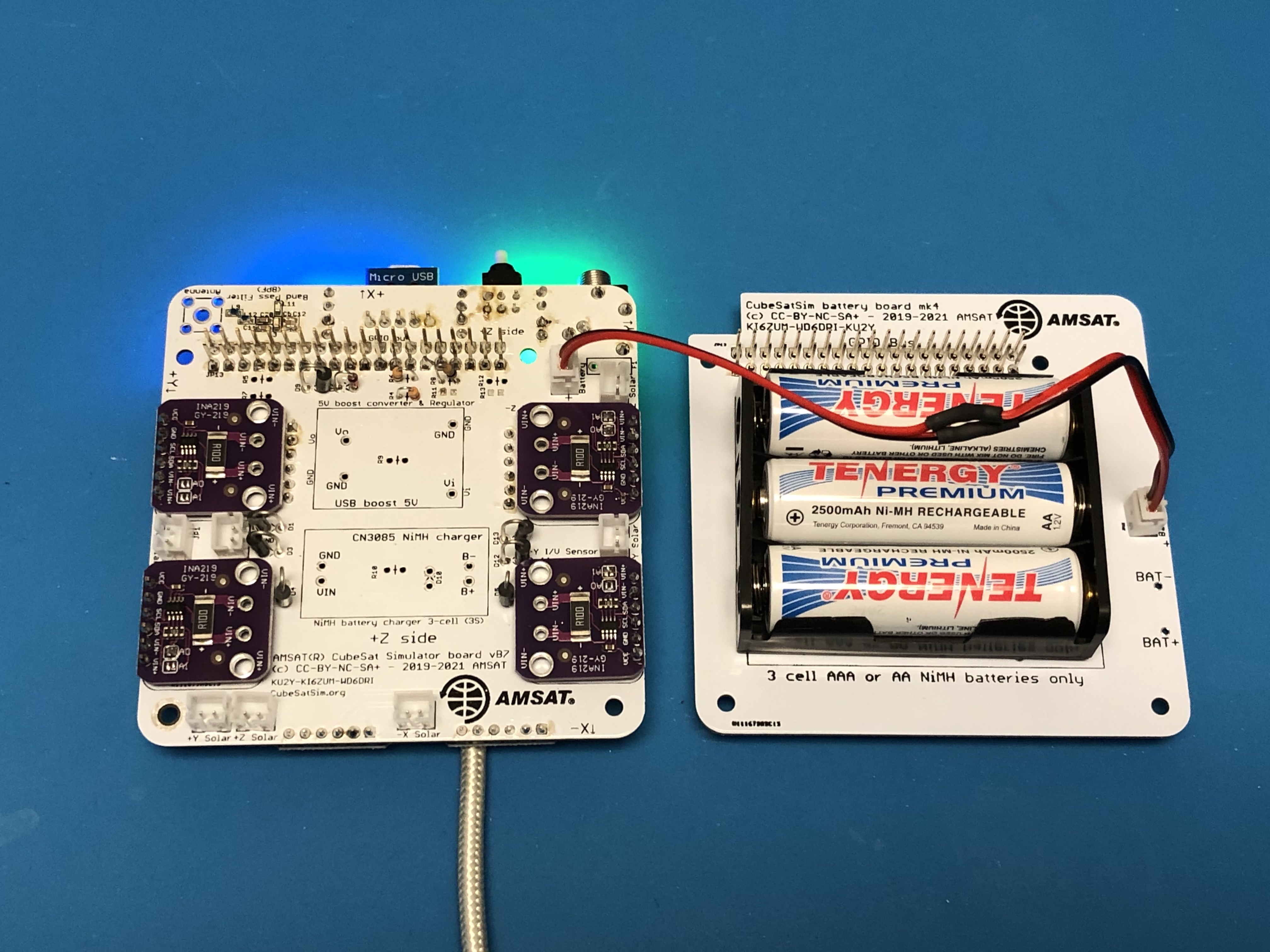
Here is a completed Battery board with AA batteries and the JST cable plugged into the JST connector on the board:
It is a good idea to test your battery polarity using a voltmeter. Use the + and - test points on the board, being very careful not to short them together:
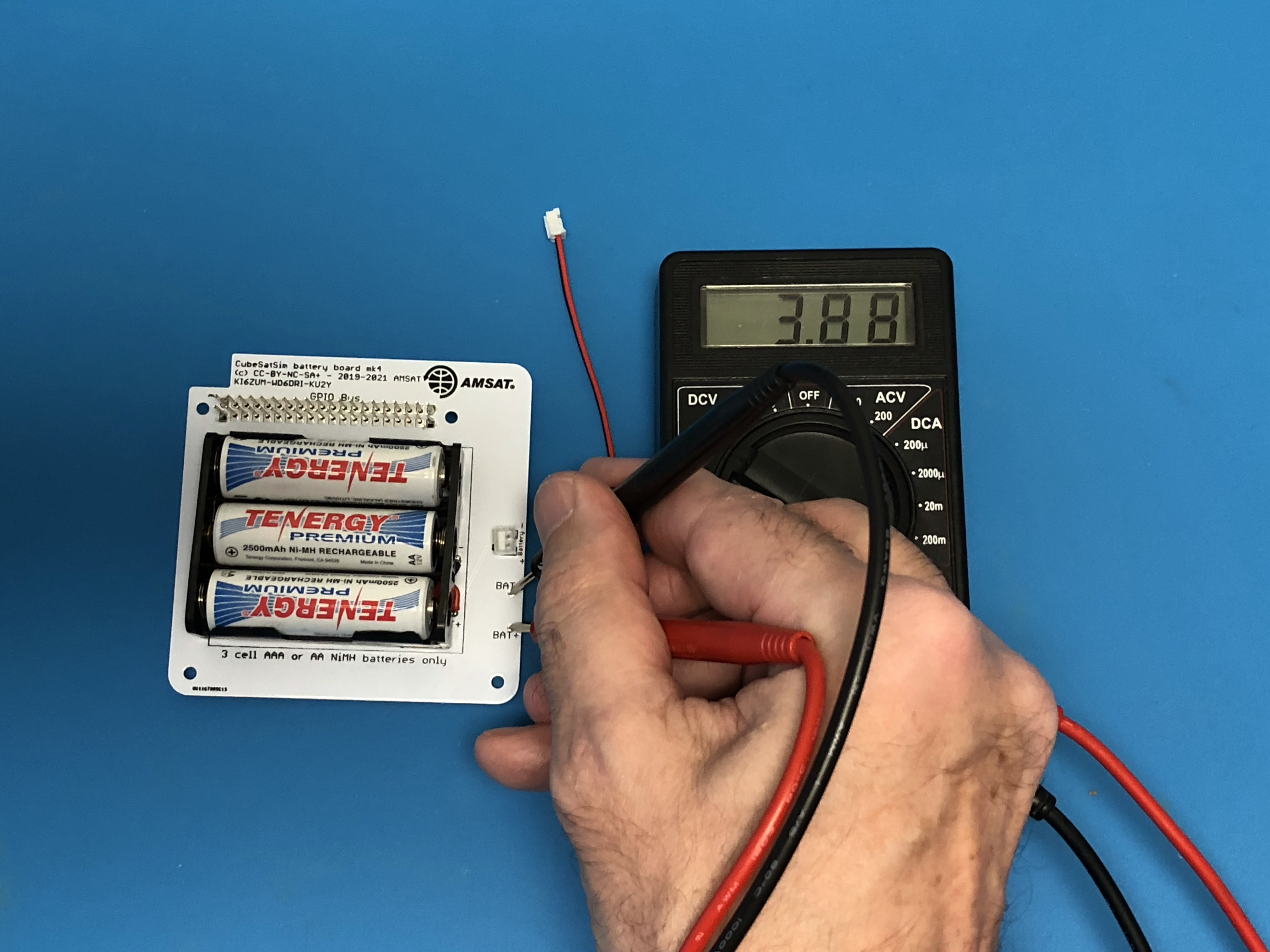
If you read a positive voltage in the range 3V - 4.5V, your Battery board is "nominal" and ready to be used.
5V Bus Voltage Sensor Test
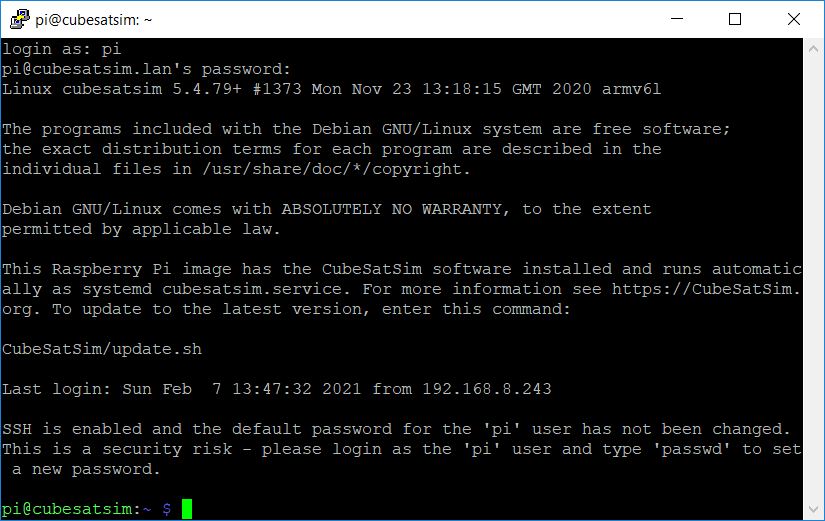
You can now test the INA219 Current and Voltage (I/V) sensors. To do this, you will need to type commands into the command line on your Pi. If you have an HDMI monitor connected via a mini-HDMI to HDMI adapter, and a keyboard connected via a micro USB to USB adapter (OTG cable), you can type the commands on the keyboard. If your Pi is on your WiFi network, you can SSH into the Pi and login. If you have a Pi Zero, you can SSH via the USB cable. You will see this:
Plug the Pi into the main board and connect the power cable to the Pi micro USB port. After booting, the CubeSatSim software will run. If you have installed the 5V Bus I/V Sensor, you can test it after logging in and opening a terminal window and typing:
CubeSatSim/telem
You should see a non-zero voltage for each I/V Sensor that is installed and a voltage close to 5V for the Bus as shown below. The current will read zero since you are powering the Pi directly, not through the Main Board:
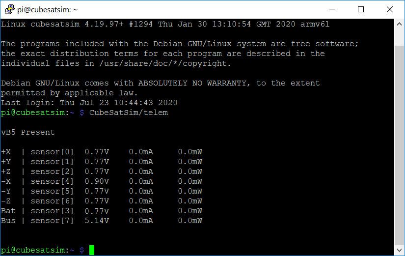
If you don’t get a voltage, there might be a problem with the 5V Bus I/V Sensor such as the wrong address setting. If you get any errors displayed, there might be a problem with the I2C bus. Check the resistors R4 and R6. Also, check the addresses of your INA219 boards. The 5V board is on the bottom of the PCB on the top right side, which should have the address 0x45.
Battery Voltage Sensor Test
If your Battery Board is built, you can test the Battery I/V sensor. In the terminal window type:
sudo systemctl disable cubesatsim
This will stop the CubeSatSim software so that the Pi will not be automatically shutdown if your battery voltage is low. Next, shut down the Pi by typing:
sudo shutdown now
Once the Pi is shutdown, plug the battery connector into the Main board and press the pushbutton to start it up again.
The green and blue LEDs will not illuminate since the CubeSat software isn't running. You will have to log back into the Pi again. Open a terminal window in the Pi and type:
CubeSatSim/telem
and you should see a non-zero voltage for each I/V Sensor that is installed and a voltage for the Battery between 3V and 4.5V. For example, this shows all six I/V Sensors installed and a battery plugged in.
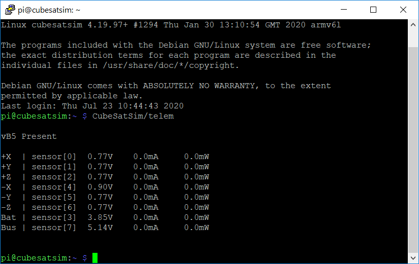
The current will read zero since you are powering the Pi directly, not through the Main Board. When you are done testing, restart the CubeSatSim software by typing:
sudo systemctl enable cubesatsim
The software will start the next time the Pi turns on.
If you don’t get a voltage for your battery, there might be a problem with the Battery I/V Sensor which is on the bottom of the board on the top left with address 0x44. Or, there might be a problem with your Battery Board such as an incorrect wiring or polarity, or a battery cell popped out or reversed.
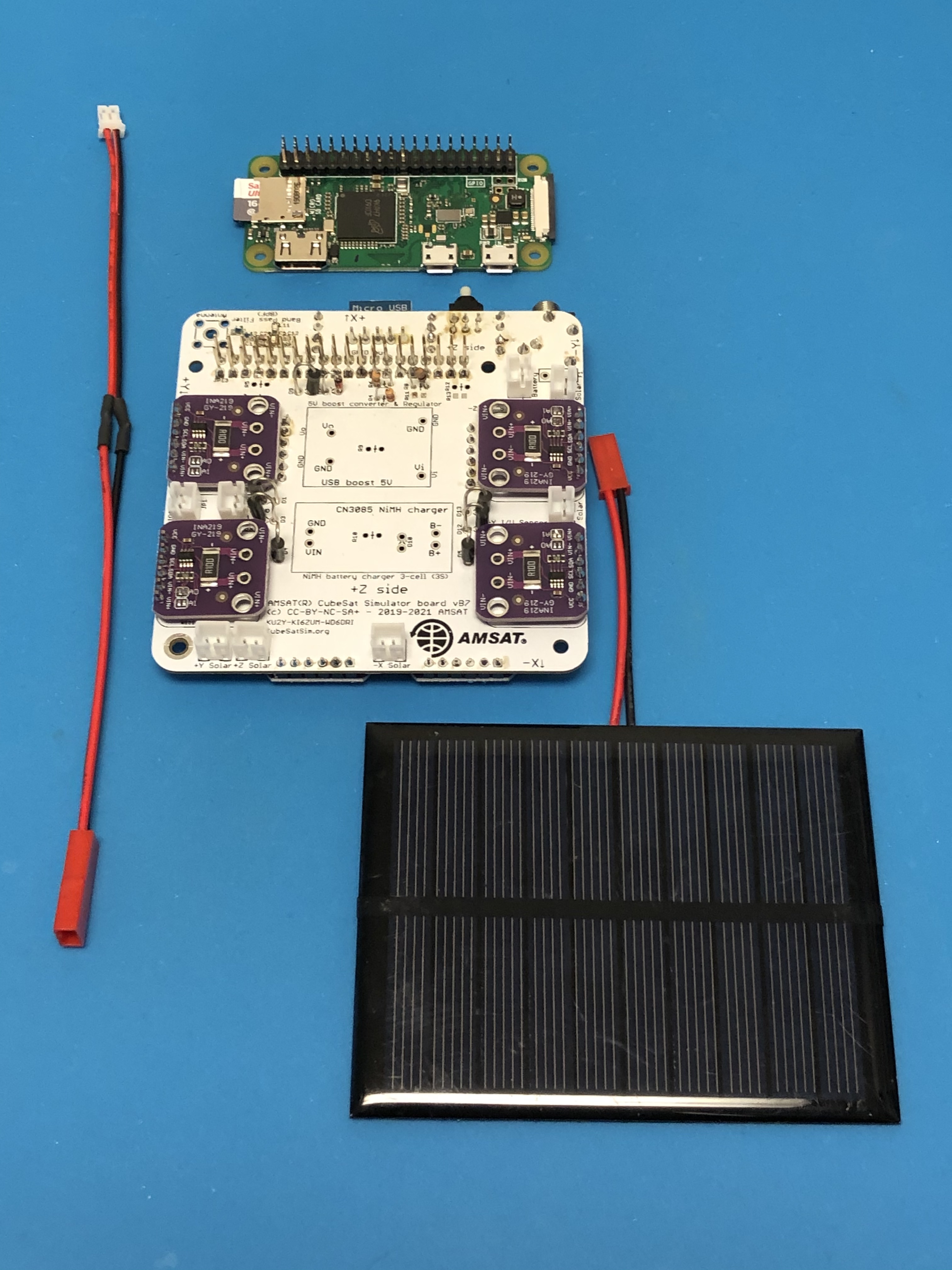
Solar Panel Voltage Sensor Test
To test the solar panels, you need to have at least one solar panel and cable soldered up. You will need your Pi with the micro SD card with the CubeSatSim software, your Main board, a Solar Panel and JST cable (a JST 2.0 cable soldered red to red and black to back to a JST RCY cable). The Battery board can be either plugged in or unplugged.
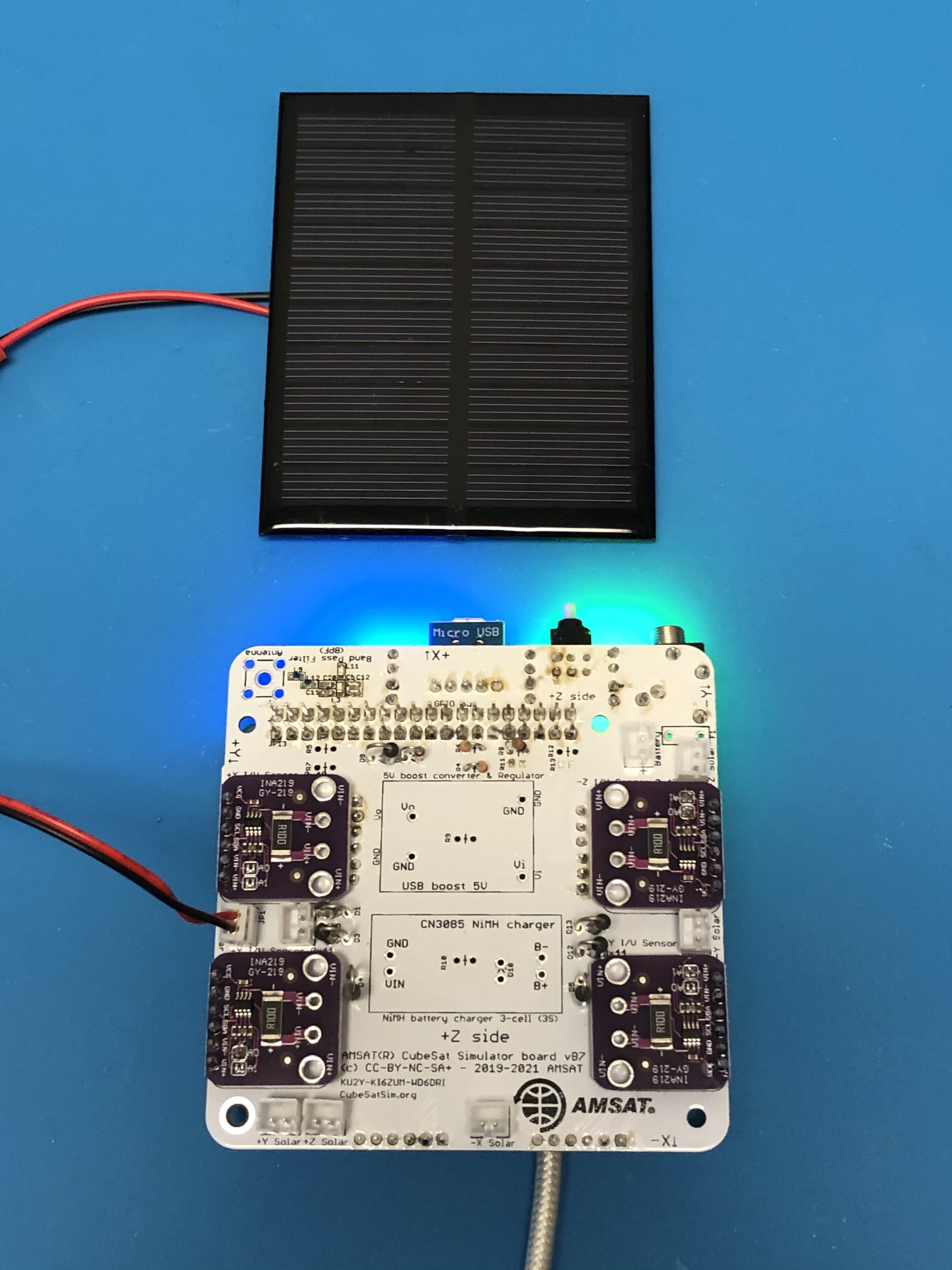
With the Pi plugged into the Main board and the power cable plugged into the Pi micro USB port, after booting, the CubeSatSim software will run. Plug the Solar Panel into the JST cable and plug the cable into the Main board into the +X Solar JST connector (left side of PCB):
Open a terminal window in the Pi and type:
CubeSatSim/telem
and you should see a non-zero voltage for each I/V Sensor that is installed. If you have a Solar Panel plugged into an I/V sensor and it is illuminated, you should see a voltage greater than 2V. For example, this shows only the +X I/V Sensor installed and a Solar Panel plugged into it:
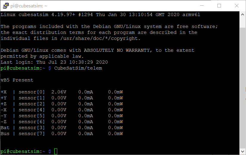
If you don't see a voltage for the +X Solar Panel, check the wiring on your solar panel and make sure it is plugged into the +X Solar JST connector.
And this time with the solar panel under stronger illumination:
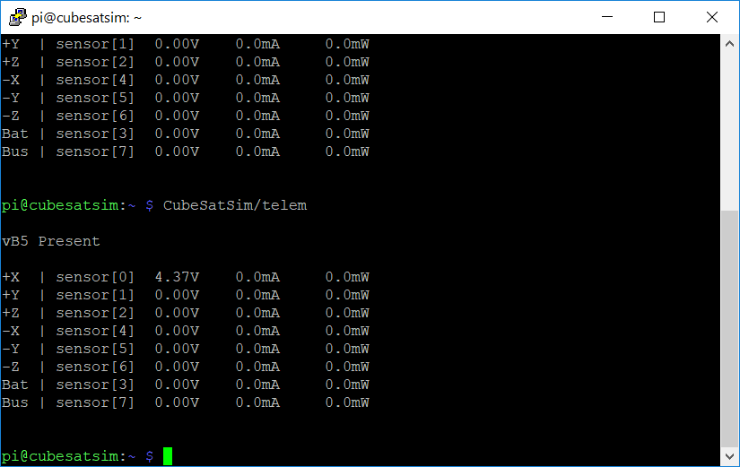
You can move your solar panel connection around to all the connections to test them such as -X, +Y, -Y, +Z, and -Z.
If you see an error displayed, the I2C configuration on the Pi might be incorrect. If you don’t get a voltage, there might be a problem with the I/V Sensor such as the wrong address setting.
If you have your Ground Station running, you can restart your CubeSatSim by pressing and releasing the pushbutton. When you start the DUV telemetry decoding in FoxTelem, you can see the individual solar panel voltages in the Health tab.
Finishing the Main Board - Battery charging circuit
Cut four individual pin headers and two 1x2 pin headers, and insert in the board (do not solder yet) for the 5V boost converter board and NiMH charger board as shown:
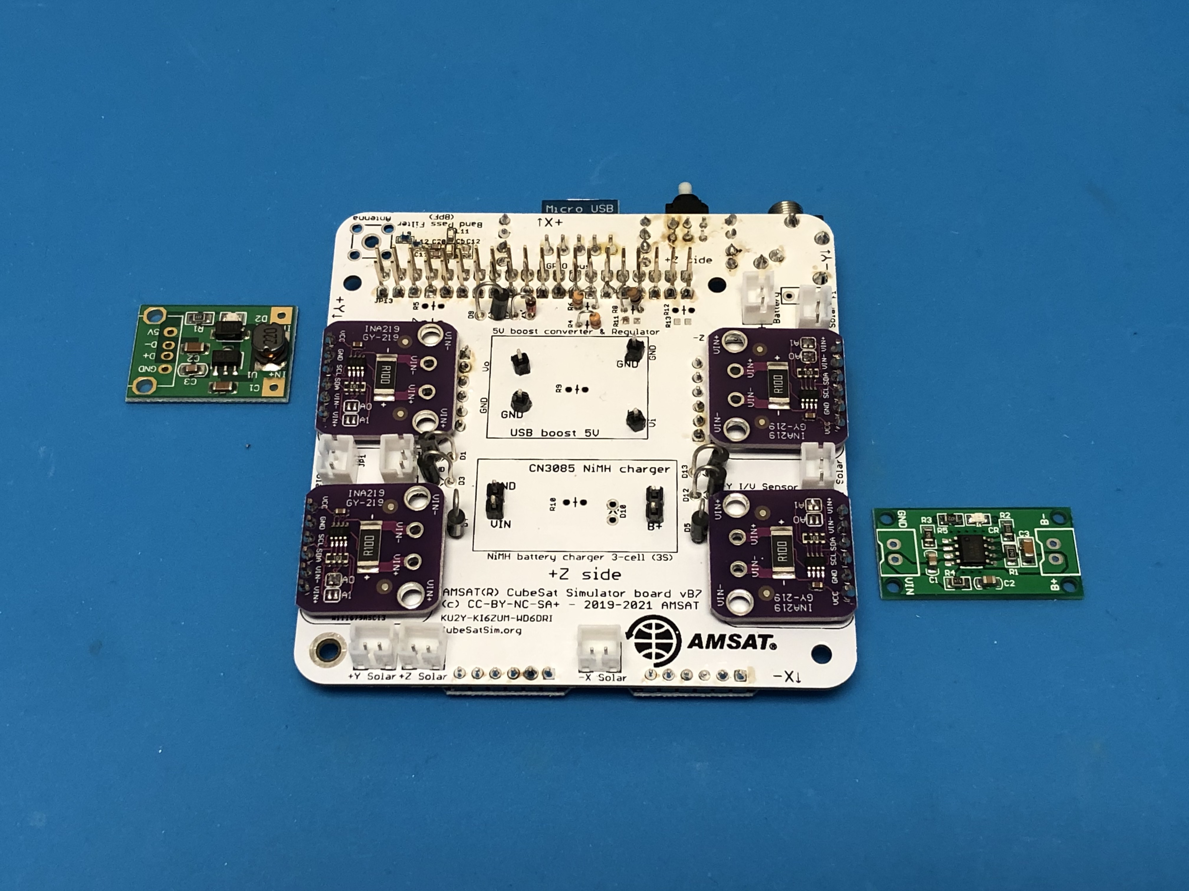
Then, place the 5V boost converter board and NiMH charger board on the pins:
Solder the top of the pins:
Then turn the board over and solder the pins to the bottom of the PCB. Insert and solder in the PTC resettable fuse F1 near the top right of the board:
The bottom of the PCB should look like this:
The main PCB is now complete!
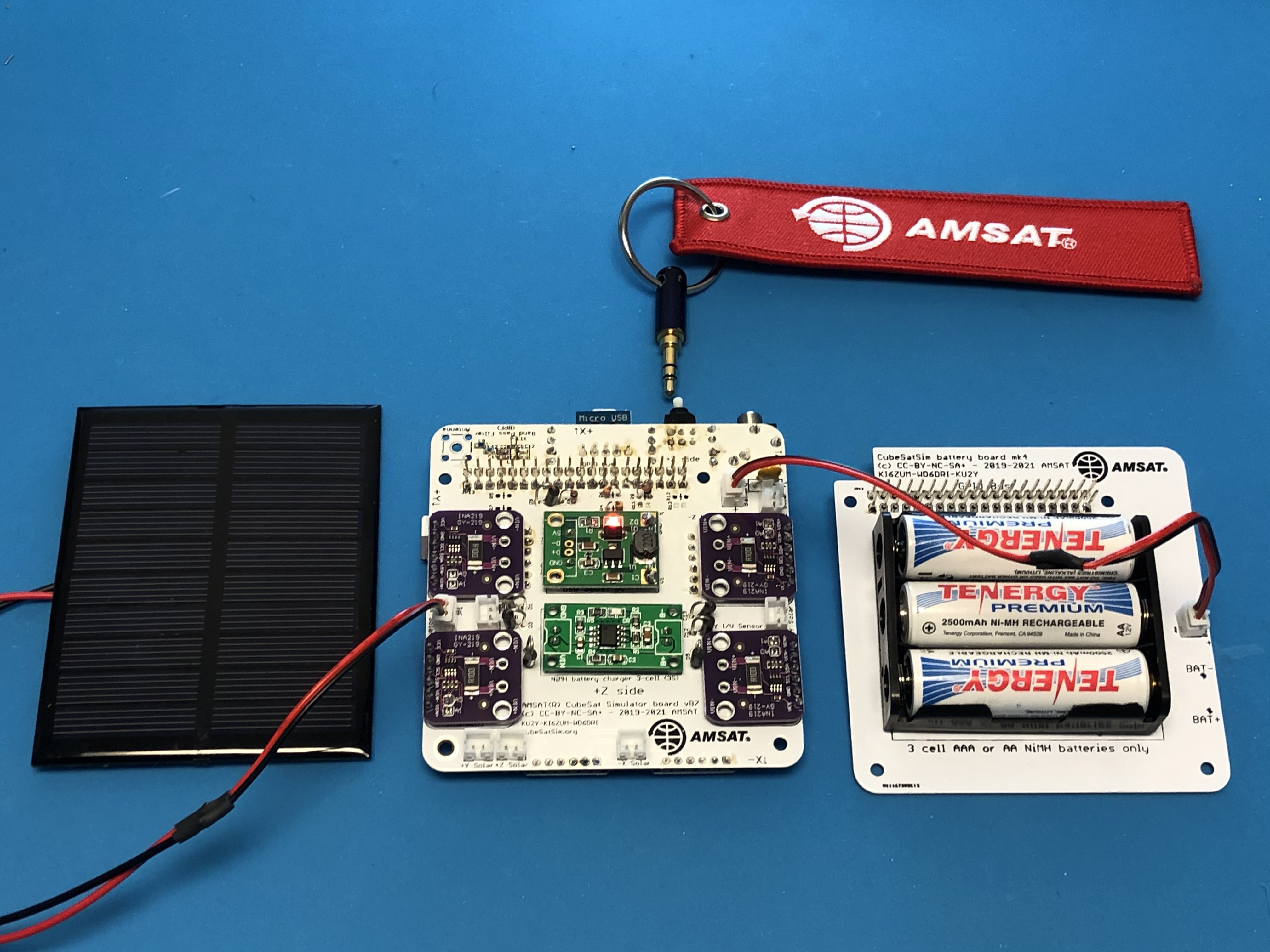
For these tests, use an arrangement known as a "Flat Sat" where the various CubeSat boards are connected side by side instead of stacked so you can get access to everything.
Running on Battery Test
The CubeSatSim will now run on a charged battery (battery voltage higher than 3.2 V). Removing the RBF pin will turn on the CubeSatSim. A single red LED will illuminate on the 5V Regulator board, as shown here:
If the CubeSatSim does not turn on and the red LED doesn't illuminate on the 5V Regulator board, make sure the PTC F1 is soldered in correctly and the RBF switch is soldered in and the RBF pin is removed. Also make sure the battery voltage is greater than 3.2V and the battery JST cable is plugged into the Main board and the Battery board.
Charging Test
When you plug in the power cable to the Board micro USB port, the red LED will illuminate and a small red LED will illuminate on the Battery Charging Board.
In FoxTelem, the Battery Voltage will jump up and the Battery current will be negative, indicating the current is flowing into the battery to charge it. If the battery is discharged, this could be around 300 mA, or less than 100 mA for a fully charged battery.
If you don’t get charging or the red charging LED doesn’t illuminate, there might be a problem with the Charging Board or your USB charging cable or outlet.
Solar Panel Current Sensor Test
In FoxTelem or using telem command line, verify that each Solar Panel (+X, -X, etc) generates current under sunlight or halogen illumination.
If no current flows, make sure the Solar Panel is getting good illumination from the sun or a lamp. An LED lamp will need to be positioned very close to the solar panel to generate a current. A low solar panel voltage (around 2V) can be generated from ambient light, while a direct lamp illumination is needed for a higher solar panel voltage (around 4V).
RBF Switch Test
Shutdown the CubeSatSim by pressing and holding the pushbutton. Insert the RBF pin. Verify that pressing the pushbutton does not start the CubeSatSim with the RBF pin inserted. Verify that removing the RBF pin makes the CubeSatSim turn on.
If removing the RBF pin does not start the CubeSatSim, make sure the battery is connected and not fully discharged. Make sure the Pi is plugged in and has a programmed micro SD card. If the RBF pin inserted does not prevent the CubeSatSim from starting, check the installation of the RBF switch.
Results
If your CubeSatSim has passed all these tests, congratulations, the status of your CubeSatSim is “nominal” :-)
Note: For a spacecraft, “nominal” means fully functioning with no anomalies or problems.
Next, build the STEM Payload Board.
Then you are ready to put the Board Stack together.