vB4 Arduino Payload - alanbjohnston/CubeSatSim GitHub Wiki
Building the STEM Payload Board
This is the archived instructions for building and testing the vB4 STEM Payload board. The latest instructions for the v1.0 STEM Payload board are here.
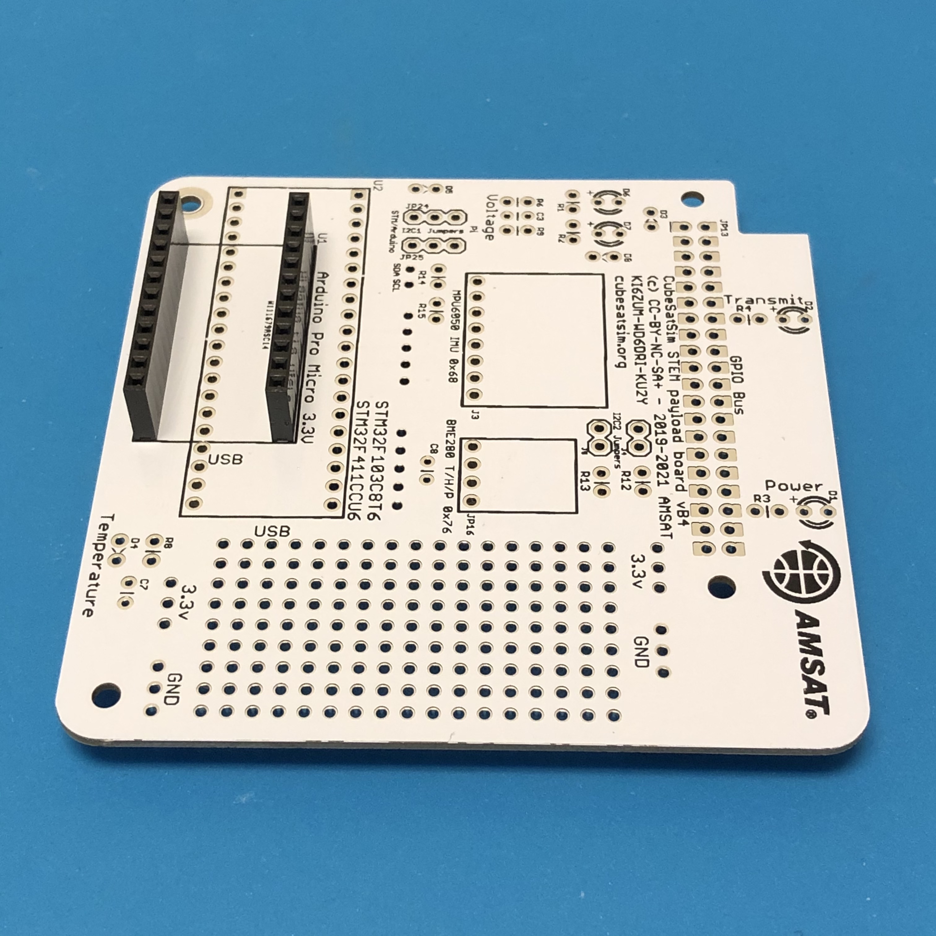
These instructions are to build and test the STEM Payload board. You can get the STEM Payload board at the AMSAT Store.
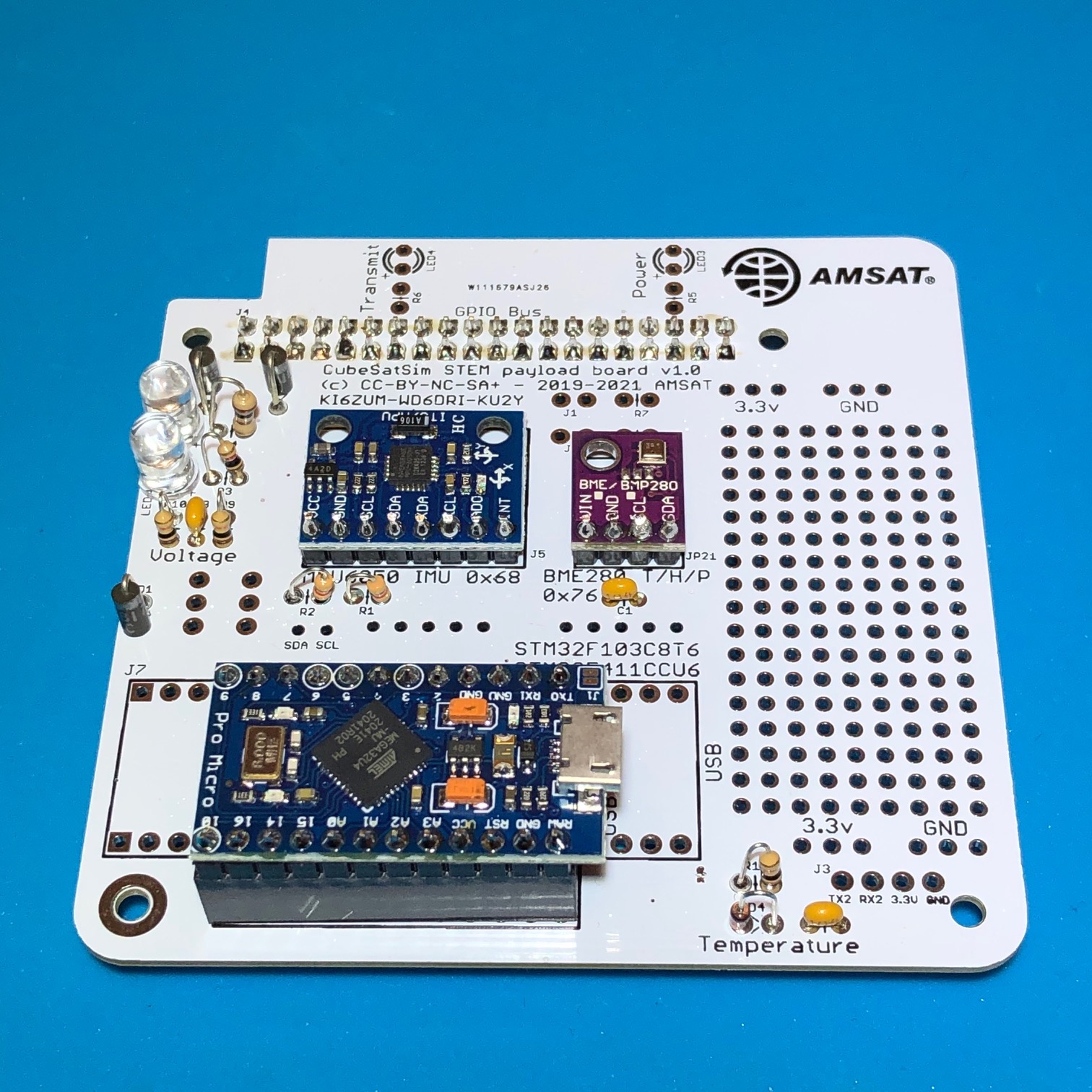
This is the STEM Payload PCB Board along with the SparkFun Pro Micro board and the STM32 "blue pill" board.
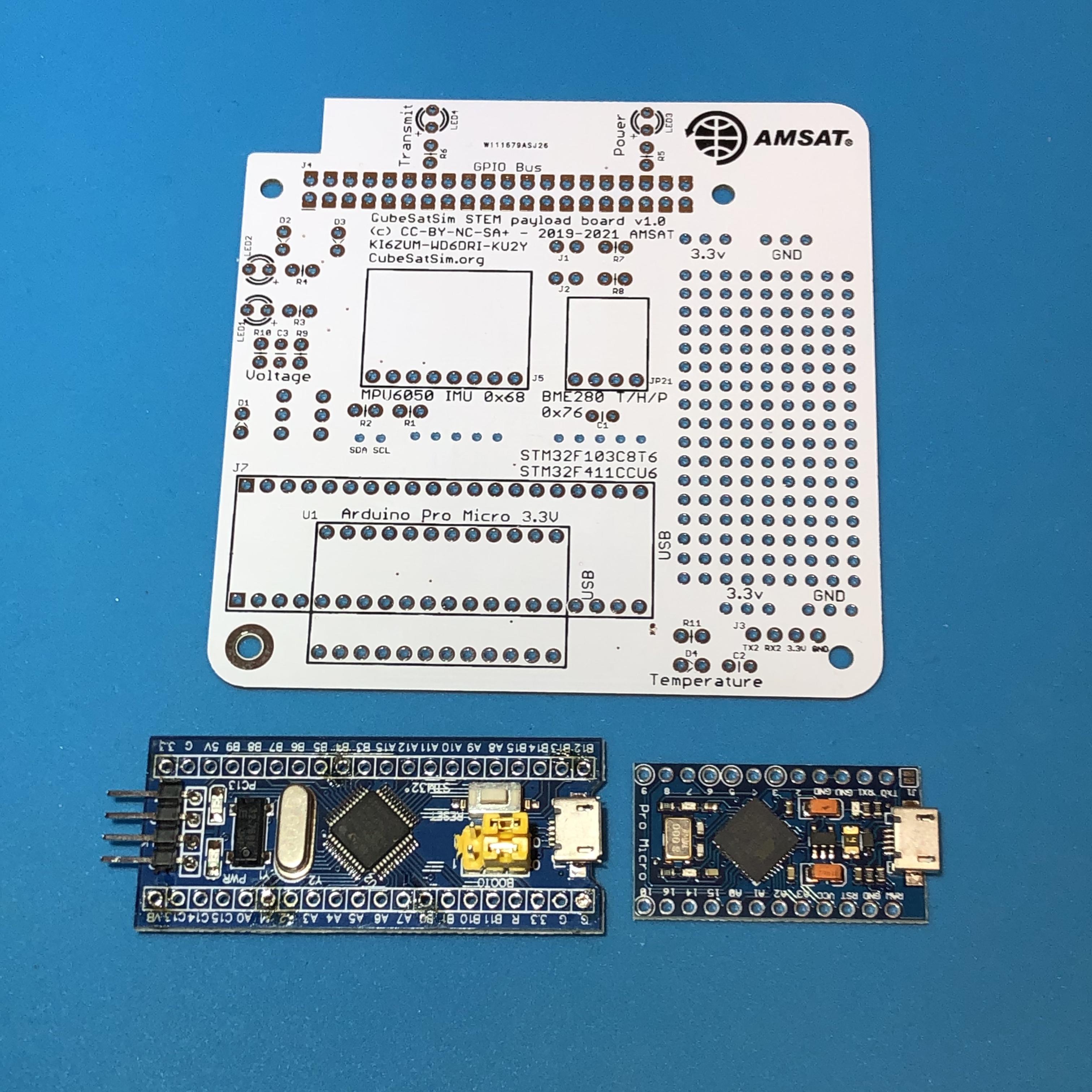
The STEM Payload Board can use either the Sparkfun Pro Micro microcontroller or the STM32F103C8T6 microcontroller, also known as a "blue pill". I recommend using the Sparkfun Pro Micro board since it is Arduino compatible and does not need to be flashed, making it a simpler alternative to the "blue pill". Note that the Sparkfun Pro Micro is usually red in color - this is a clone in blue. The "black pill" STM32 board will also be supported in the future.
I strongly recommend using sockets for your Pro Micro or STM32. This way, you can program and test it unplugged from your board. This will help you figure out if any problems are a hardware or software issue.
Here is the basic setup instructions for the Pro Micro board: In Windows, the drivers should automatically install the first time you plug the Pro Micro board in using a micro USB cable. If not, there are instructions here https://learn.sparkfun.com/tutorials/pro-micro--fio-v3-hookup-guide which includes links to download the drivers. This link also has MacOS and Linux instructions, too.
I'd recommend using the Arduino Integrated Development Environment (IDE) application to program your Pro Micro or STM32, although you can use other IDEs too. Download the latest version here: https://www.arduino.cc/en/software
Before you can program your Pro Micro, you will need to install the board files for the Pro Micro. First open the Preferences under File/Preferences and you will see a "Additional Board Manager URLs" text box near the bottom. Copy and paste this URL into the box:
Click OK to save it an exit the Preferences. Next under the Tools menu, mouse over the Board menu item and you should see the Boards Manager listed at the top. Click on it and it will open after a few minutes. At the top, there will be a search bar. Type in Sparkfun and search and you will see a listing for Sparkfun AVR Boards by Sparkfun Electronics. Click Install. When it finished the installation, click Close.
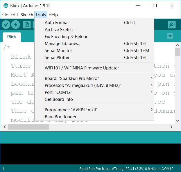
Now when you go under the Tools menu and select Board, you can select Sparkfun Pro Micro, possibly under SparkFun AVR Boards. You also need to select the correct version of the board. We use the 3.3V version of the board - if you look at the bottom of the Pro Micro board, the 3.3V option should be checked. If you accidentally purchased the more common 5V version of the board, you will need to get the 3.3V version. Under the Tools Menu, the Processor option should be set to ATmega32U4 (3.3V, 8 MHz). You will also have to select the Port for the Pro Micro. Here's what it will look like in the Arduino IDE when you are ready to program your Pro Micro (your COM port will likely have a different number):
Now you are ready to program it for the first time. I'd recommend the Blink program to flash the built-in LED on the board. Here it is (works for both the Pro Micro and STM32):
https://github.com/alanbjohnston/CubeSatSim/blob/master/arduino/Blink.ino
After copying this code and Uploading to your board, the LED should blink. Now you are ready to build your STEM Payload board!
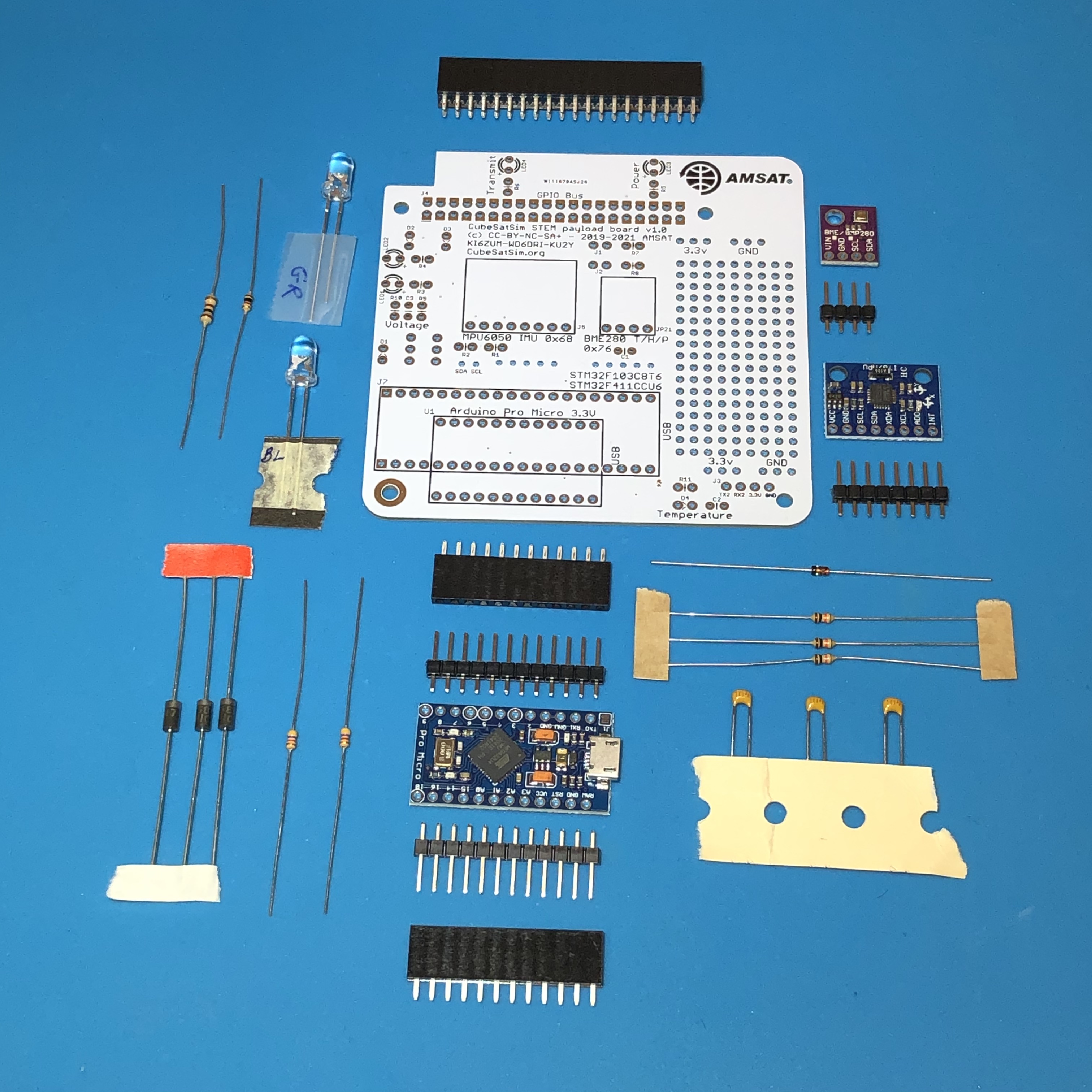
The components are:
- Sparkfun Pro Micro microcontroller (3.3V, 8 MHz version) with two breakaway pin headers (alternatively a STM32F103C8T6 microcontroller mounted with two breakaway headers).
- 1N5817 diodes D1, D2, and D3 to supply power to the Board.
- JP24 and JP25 jumpers made with two 1x3 male pin headers and two jumpers.
- 4.7k Resistors R14 and R15 as pullups for the I2C bus
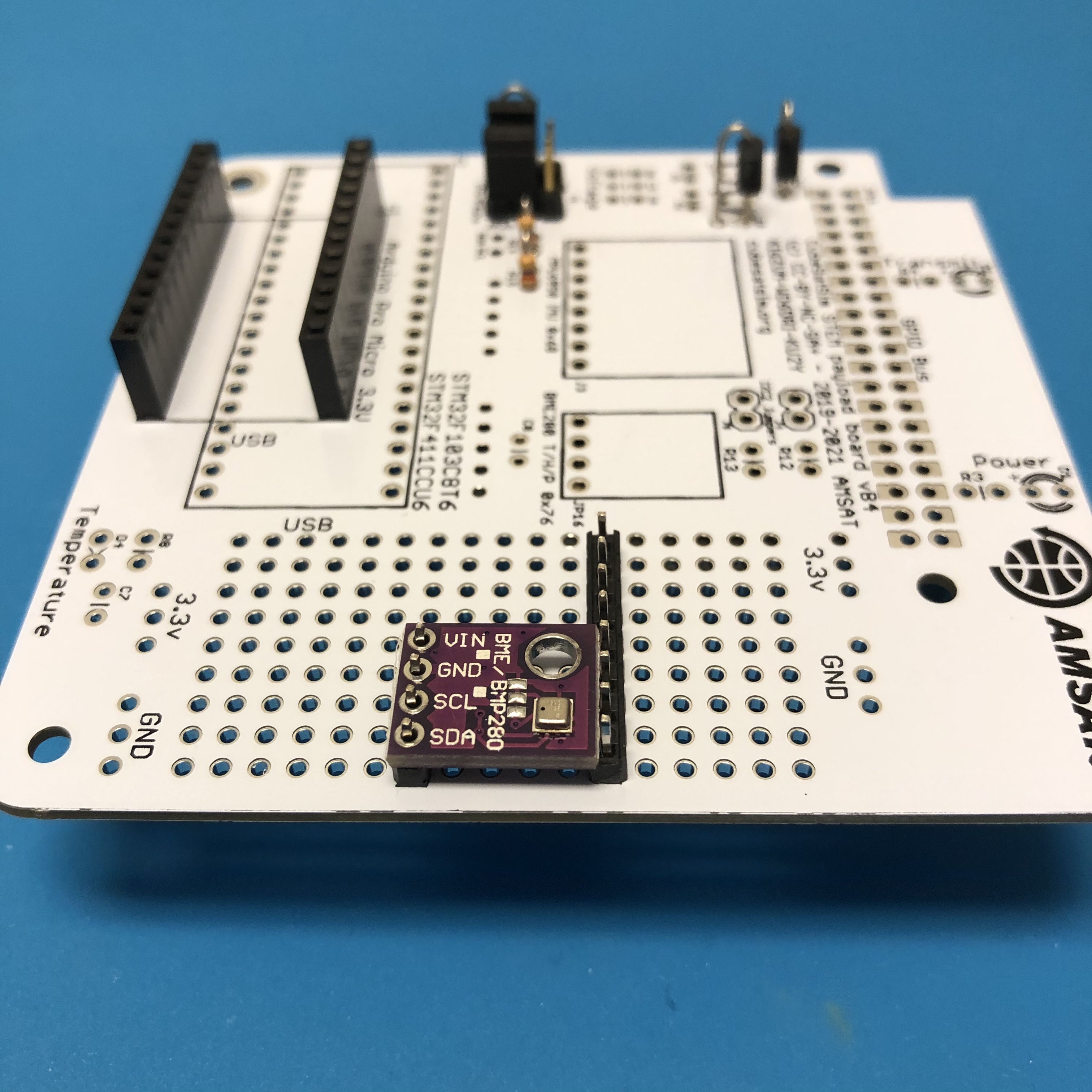
- BME-280 Temperature Humidity Barometric Pressure Sensor (small purple board) with 1x4 pin header
- MPU-6050 (GY-521) 3-Axis Accelerometer and Gyro (larger blue board) with 1x8 pin header
- GPIO female non-stacking connector
The additional components to complete the board are:
- 100nF capacitors C3, C7, and C8
- Diode D4 1N4148 (has "41" and "48" printed on it)
- Green LED 5mm clear lens
- Blue LED 5mm clear lens
- 10k resistors R6, R8, and R9
The complete set of parts is shown here:
Start by mounting the female pin headers for the Pro Micro or STM32. It is important that the spacing and the alignment of the two headers is correct. One way to do this is to use the male pin headers that come with the Pro Micro or STM3s to set the distance, as shown here:
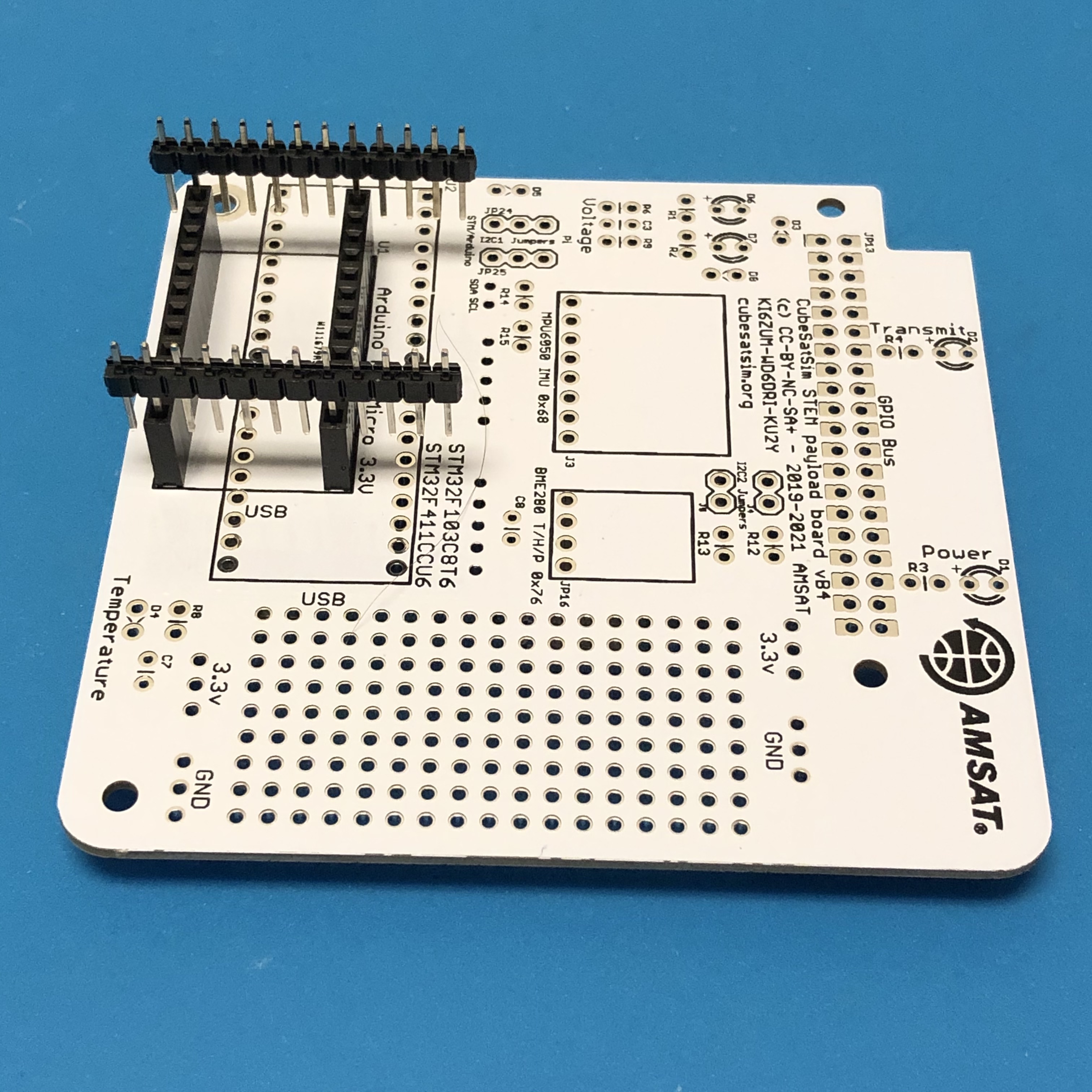
Once the headers are soldered in, they will look like this:
Next, plug the headers for the Pro Micro or STM32 into the sockets, then place the Pro Micro or STM32 on top as shown here:
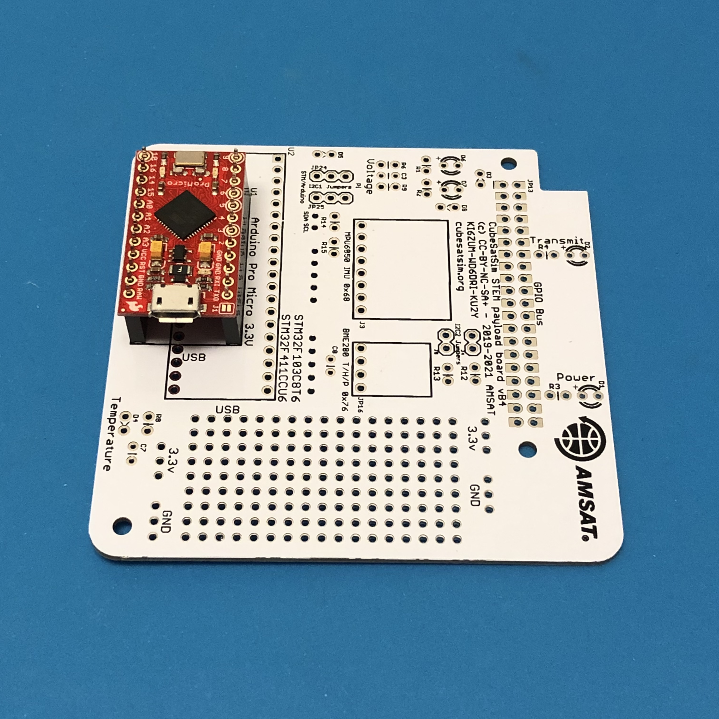
The pin headers then can be soldered onto the Pro Micro or STM32 board. Then, the micro controller can be unplugged while the rest of the components are soldered in.
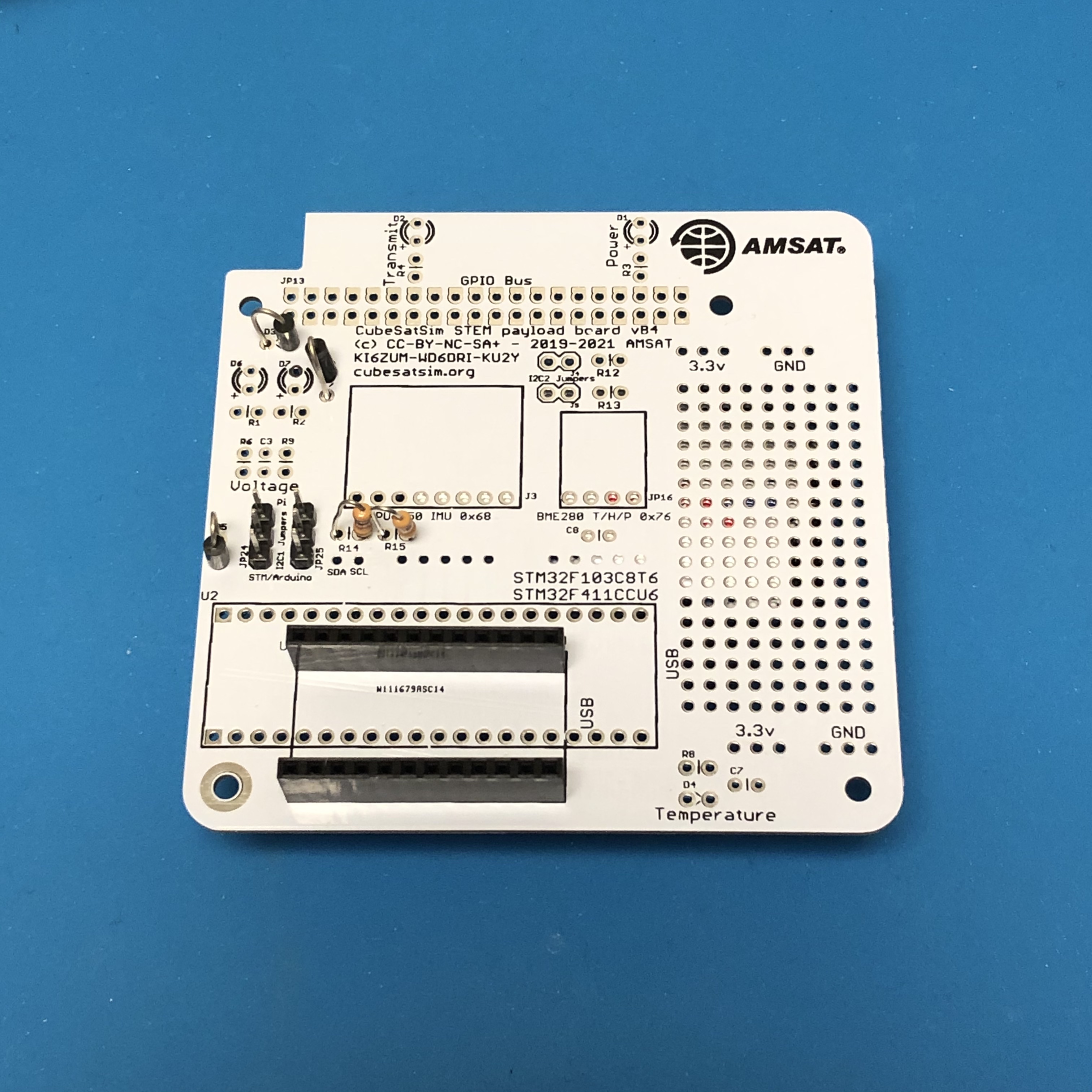
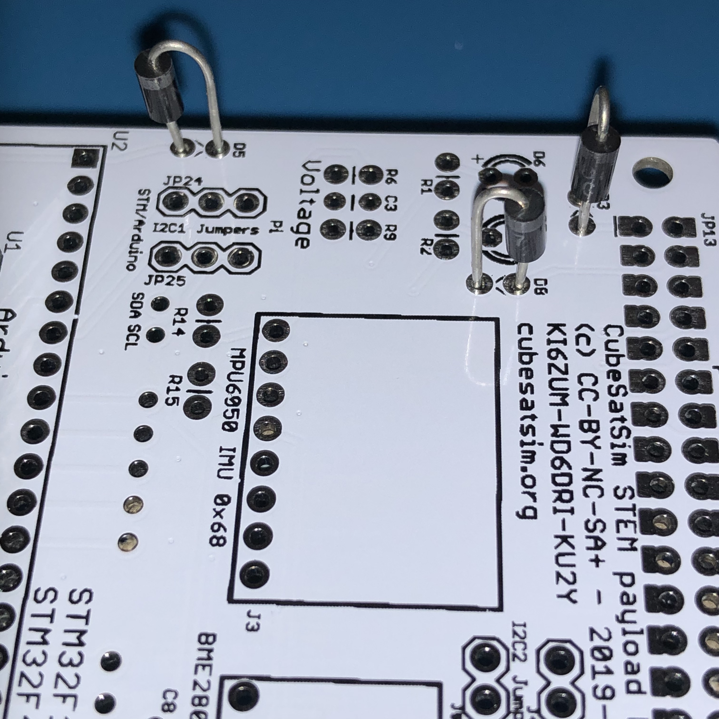
Next, solder the 1N5817 diodes D3, D5, and D8 and the two 1x3 pin headers JP24 and JP25 and the 4.7k resistors R14 and R15:
Make sure the polarity of the diodes D3, D5, and D8 is correct:
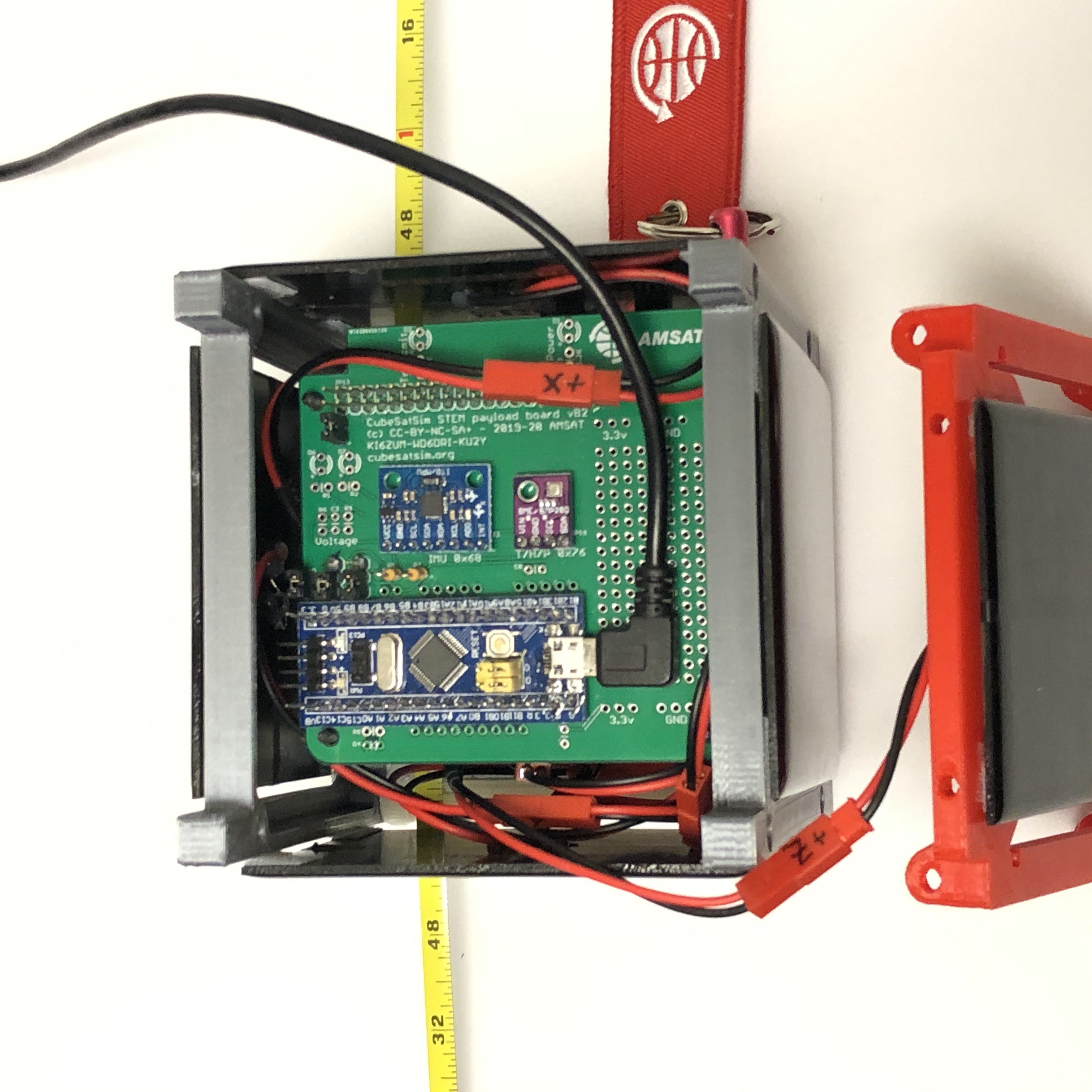
Then, mount the BME280 sensor (small purple board) on the pin header:
The same needs to be done for the MPU6050 Gyro and Accelerometer board.
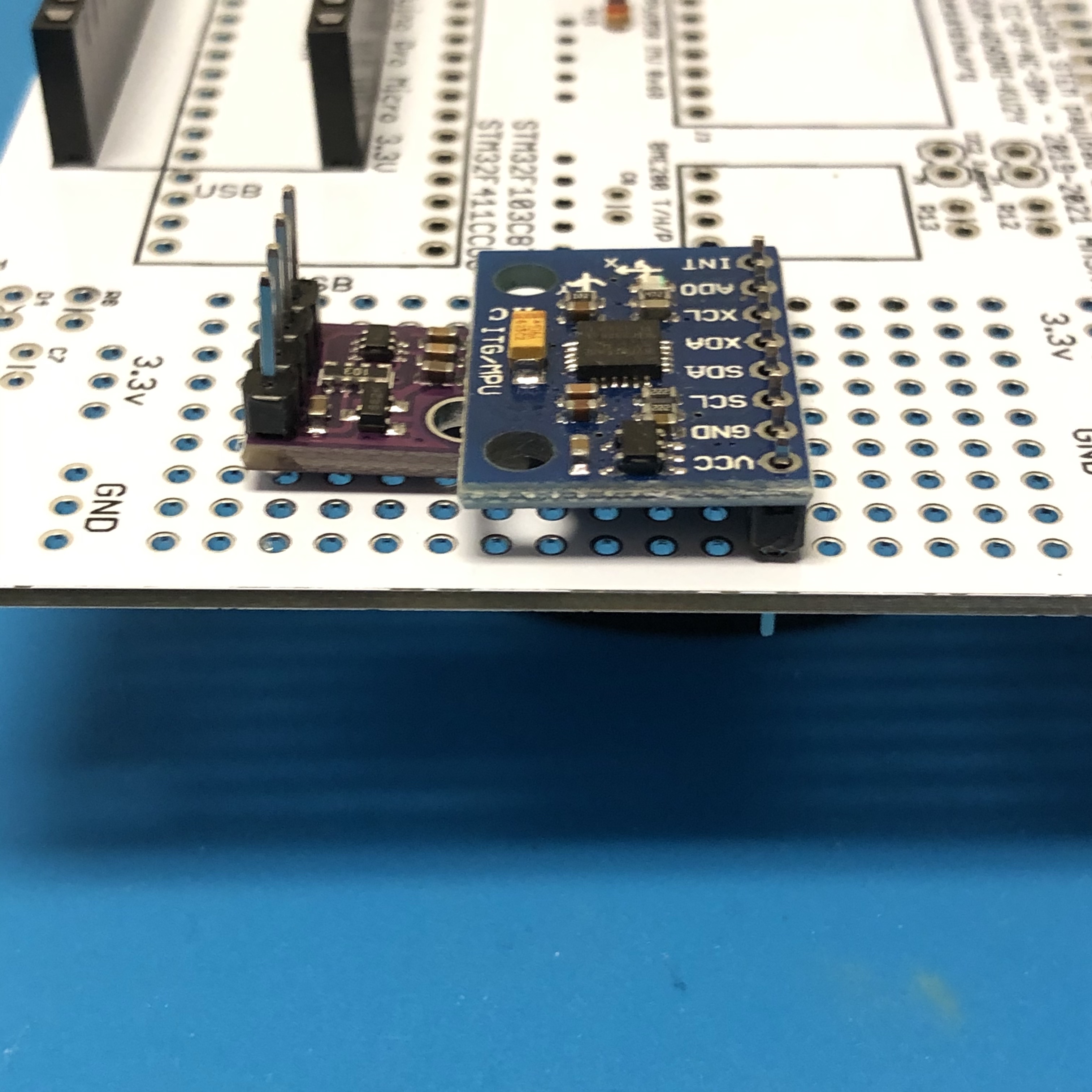
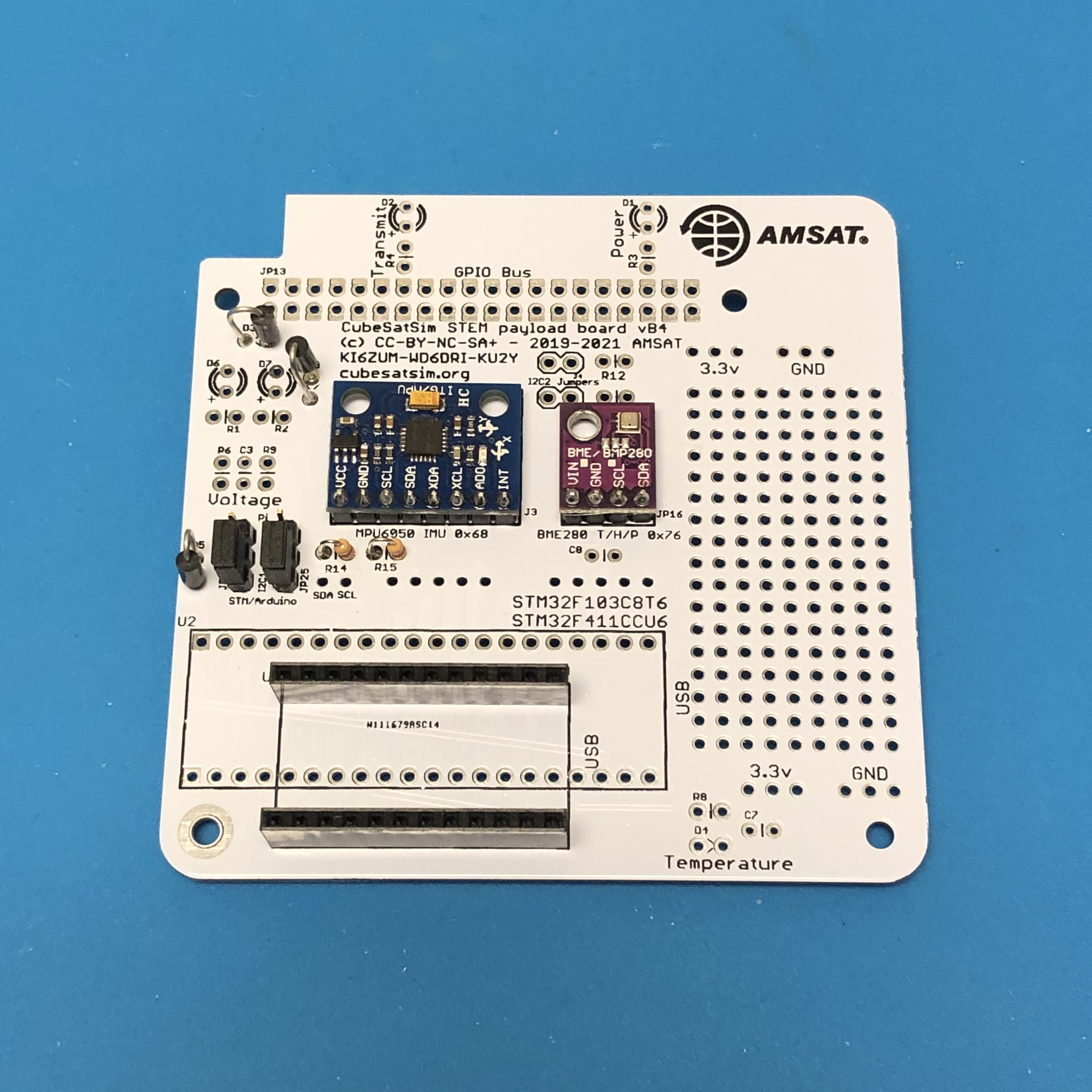
Here are both sensors installed:
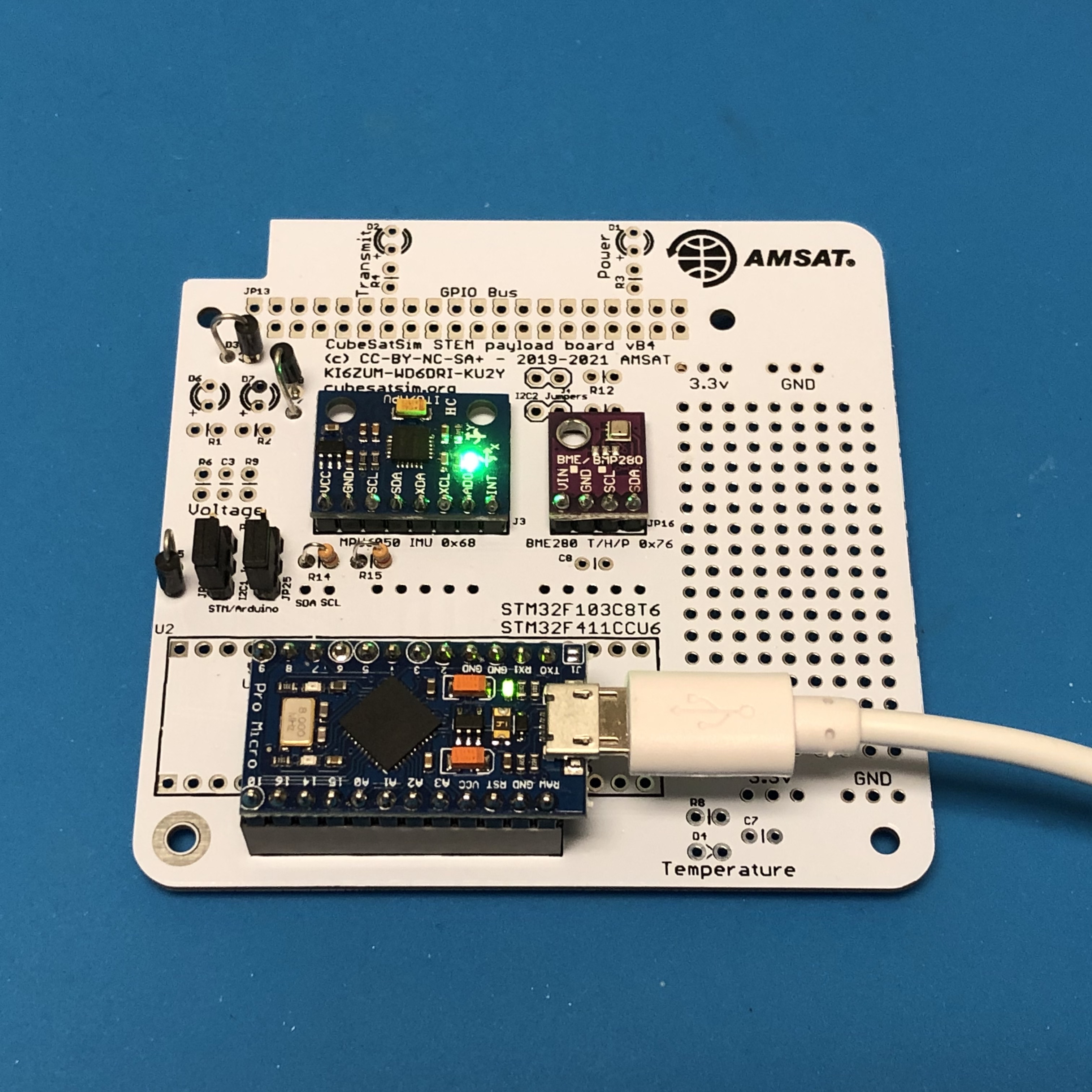
Connecting the micro USB cable to your PC will power the board and you should see a power LED on the Pro Micro and a power LED on the MPU6050 gyro (this photo shows a blue Pro Micro clone):
Payload Sensor Testing
You can now test that the Pro Micro can communicate with the two sensor boards. Here is the code that runs on both the Pro Micro and the STM32:
https://github.com/alanbjohnston/CubeSatSim/blob/master/arduino/Payload_BME280_MPU6050_XS.ino
This code requires several libraries which you will need to install. If you forget to install one or more libraries, you will get error messages saying "No such file or directory".
Open Tools/Manage Libraries and the Library Manager will open after a few moments. In the search box, type bme280 then return and you will see the Adafruit BME280 library. When you mouse over it, it will give a version pulldown menu and an Install button. Select version 1.1.0 and click on Install to install it. It should look like this:
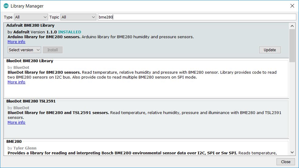
Now type adafruit then return in the search box. A long list of Adafruit libraries will appear. Scroll down to find the Adafruit Unified Sensor library. Mouse over and select version 1.0.3 and click Install to install it. Finally, type tockn then return in the search box and install the MPU6050_tockn library and click Install to install it.
Click Close to close the Library Manager. In the sketch window, click on the Verify icon (checkbox) and it should compile without errors. If you get an error saying "No such file or directory", go back to the Library Manager and make sure you have installed the correct version of all three libraries. Click on the Upload button (right arrow) and the Pro Micro should be programmed to read the sensors.
Once it is done uploading (indicated by the Done Uploading) message at the bottom of the window, open the Serial Monitor by clicking on the magnifier icon in the top right of the window. In the Serial Monitor window, make sure 9600 baud is set in the lower right. Click on the text box at the top and type a ? then click on Send. You should get a response displayed similar to this:
OK BME280 24.89 1003.96 77.61 21.13 MPU6050 -0.85 -2.48 -1.09 0.19 -0.15 1.02 XS 0 0 0.00
The OK is the status response. The four numbers after the BME280 are the temperature in Celsius, pressure in millibar, altitude in meters, and humidity in percentage read from the purple BME280 sensor. The six numbers after the MPU6050 are the X, Y, and Z axis angular rotation in degrees per second and the X, Y, and Z axis acceleration in g. If you get a series of zeros after a sensor, it means it was not successfully read by the Pro Micro. The three numbers after XS are extension sensor fields that you can set in the code by setting the Sensor1, Sensor2, and Sensor 3 variables.
If you get all zeros for a sensor, you need to determine if it is a hardware or software problem. Running an I2C bus scanner program will tell you if the sensor can be accessed on the I2C bus. The program is:
https://github.com/alanbjohnston/CubeSatSim/blob/master/arduino/i2c_scanner.ino
Upload this to your Pro Micro (or STM32) and then open the Serial Monitor. You should see:
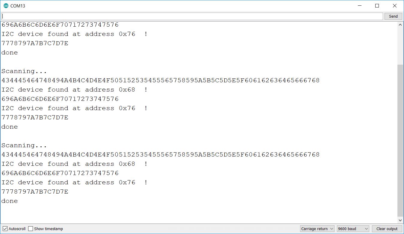
The blue MPU6050 should be at address 0x68 while the purple BME280 should be at address 0x76. If neither device is present on the I2C bus, make sure resistors R14 and R15 are soldered in and are 4.7k in value. Make sure the jumpers JP24 and JP25 are soldered in and a jumper is set to the "STM/Arduino" position (closest to the Pro Micro or STM32). If one sensor shows up but not the other, it might be due to soldering on the sensor pins or due to a bad sensor board.
If both sensors show up on the I2C bus but you get zeros in the Serial Monitor, this indicate a software problem.
Next, you can complete the build, as shown here:
You can verify all the extras work using the Payload Test sketch:
https://github.com/alanbjohnston/CubeSatSim/blob/master/arduino/STEM_Payload_Test.ino
You will then need to re-upload the Payload OK sketch:
https://github.com/alanbjohnston/CubeSatSim/blob/master/arduino/Payload_BME280_MPU6050_XS.ino
When the STEM Payload board is plugged into the the three board stack, the Pi will read the sensor data over the UART and report the data in telemetry. When the CubeSatSim software is running, you should see the built-in LED on the Pro Micro or STM32 blink every 4 seconds or so as the Pi reads the telemetry data.
In APRS (AFSK 1200) mode, the sensor string will be added to the end of the data.
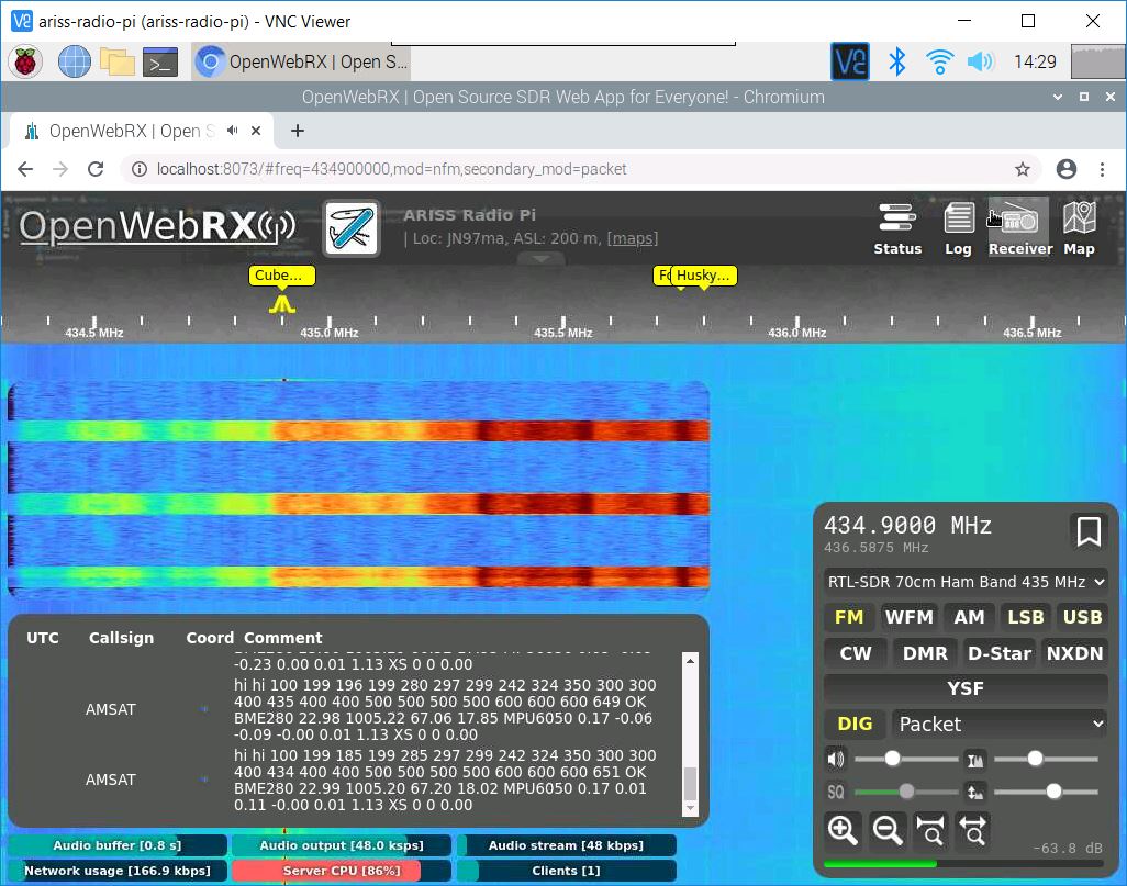
In FoxTelem, in DUV/FSK mode, under the CubeSatSim-FSK tab Health tab, Experiment box, you should see STEM Payload OK and numbers for the other fields. In addition, the rotation and acceleration will also be displayed under the +X, +Y, and +Z boxes.
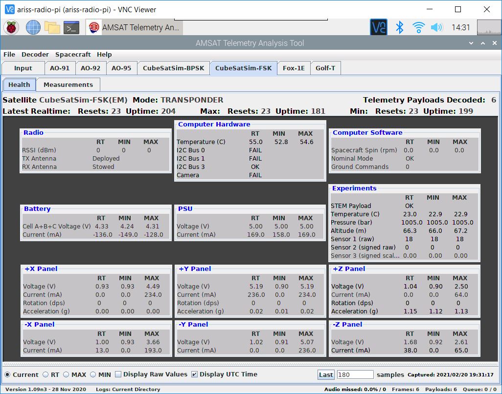
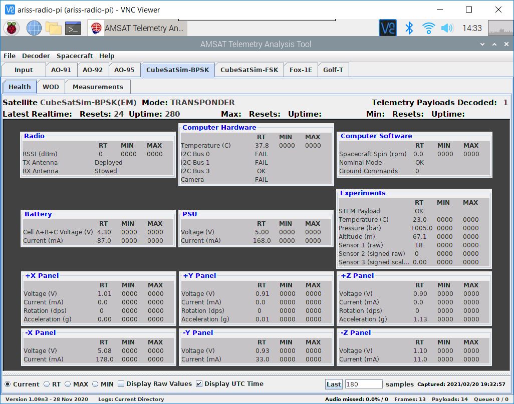
You will see the same thing in BPSK mode under the CubeSatSim-BPSK tab:
On the spinning turntable, you should see 7-10 degrees per second of rotation and the blue LED on the STEM Payload board illuminated. If the CubeSatSim is accelerated greater than 1.2g, the green LED will illuminate on the STEM Payload board.
STM32 Steps
The following steps are specific to the STM32 - you do not need to do them if you are using the Sparkfun Pro Micro.
Flashing the USB Bootloader
These instructions are for configuring the STM32 in the STEM Payload Board so that it can be programmed using the Arduino IDE. Other programming methods and IDEs can be used as well. Before you can program the STM32, you need to flash a bootloader in it so you can push code using the micro USB interface.
This section describes how to flash a USB bootloader into the STM 32.
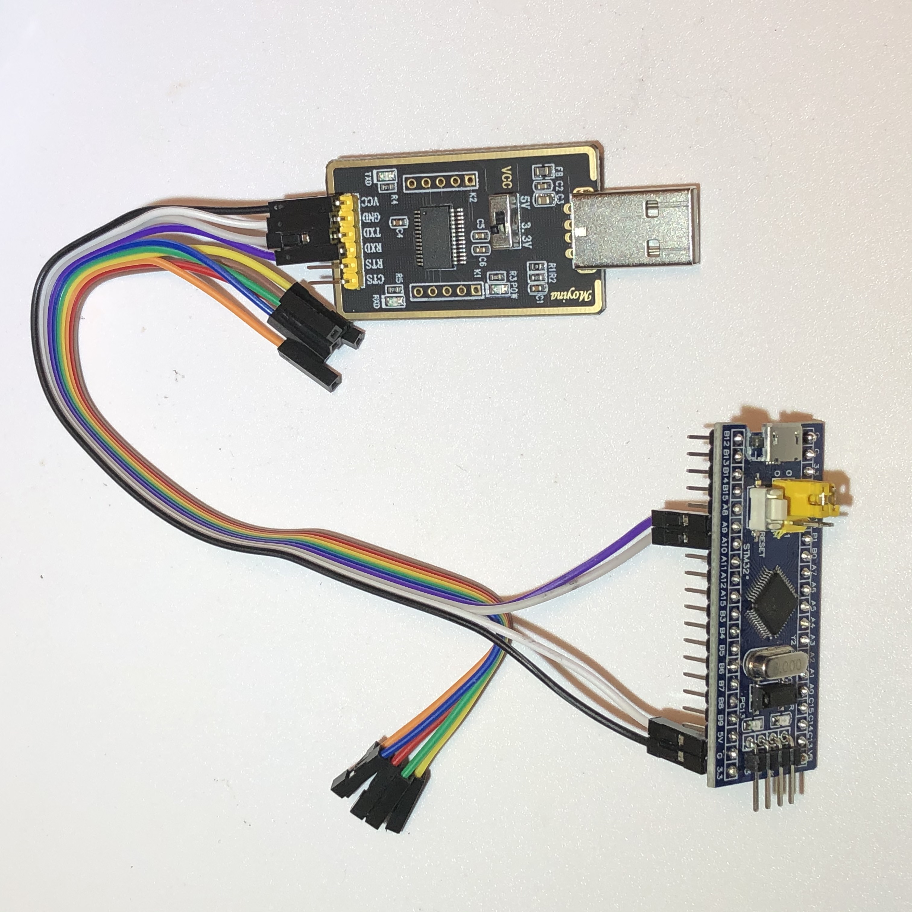
Follow the instructions https://alselectro.wordpress.com/tag/stm32-usb-upload/ For the Serial USB-TTL adapter, I used the Moyina adapter https://www.amazon.com/gp/product/B075N82CDL/ Some of the lower cost ones just don't work.
Wired up the STM32 to the USB-TTL adapter set to 3.3V
PA9 Tx to Rx of USB-TTL
PA10 Rx to Tx of USB-TTL
3v3 to 3v3 , GND to GND
This is shown here:
Download the programming tool https://www.st.com/en/development-tools/flasher-stm32.html You will need to sign up and receive email before you get a link to download. Download and install.
Download the firmware generic_boot20_pc13.bin https://github.com/rogerclarkmelbourne/STM32duino-bootloader/raw/master/binaries/generic_boot20_pc13.bin I used this version since the LED on my STM32 board is labeled PC13.
Plug USB-TTL in to USB of computer.
Set jumper Boot 0 to position 1 (closest to edge).
Run flash_loader_demo_v2.8.0.exe to install app in Program Files (x86)/STMicroelectronics/Software STMFlashLoader Demo.exe
Select a Port say Next. Get Target is readable message. Select Next.
2nd option is Download to device/Download from file. Click on the box to get the menu. Change file type to *.bin and select the .bin file downloaded earlier.
Select Next and it will start and you should see a green "Download operation completed successfully" message.
BEFORE YOU UNPLUG ANYTHING, move the jumper back to position 0.
Now, when you plug in the STM32 using the micro USB connector, it will show up as "Maple Mini". If you run the Arduino IDE, select the right port for the STM32 and open the Serial Monitor set to 9600 baud, you will see this message displayed:
Congratulations, you have installed the STM32duino bootloader
See https://github.com/rogerclarkmelbourne/STM32duino-bootloader
For more information about Arduino on STM32
and http://www.stm32duino.com
Arduino Programming IDE
To use the Arduino IDE to program the STM32; plug the STM32 to your computer using a right angle micro USB cable:
Follow the STM32duino installation instructions here:
https://github.com/rogerclarkmelbourne/Arduino_STM32/wiki/Installation
Run the Arduino IDE. The settings under Tools should be:
Board: "Generic STM32F103C series" under STM32F1 Boards (STM32duino.com)
Variant: "STM32F103C8 (20k RAM, 64k Flash)"
CPU Speed(MHz): "72MHz (Normal)"
Upload method: "STM32duino bootloader"
Optimize: "Smallest (default)"
Port: Some COM port here, labeled Maple Mini should be listed.
It should look like this (although your port number will likely be different):

Open Examples/A_STM32_Examples/Digital/Blink and edit LED pin from PB1 to PC13 and compile. You should see blinking! Note that when I use my Mac, I have to reset the STM32 after each push to get it to run the new software.
If you have soldered in the other board components, you can test the STM32 and sensors.
Additional Sensor Info
The BME-280 Temperature Humidity Barometric Pressure Sensor (small purple board):
https://lastminuteengineers.com/bme280-arduino-tutorial/
The MPU-6050 (GY-521) 3-Axis Accelerometer and Gyro (larger blue board with green LED):