vB3 Board Stack Build - alanbjohnston/CubeSatSim GitHub Wiki
This section covers the building of the three board stack for the CubeSat Simulator. Once you have this together, you can Install the software.
Note that this not the latest version of the CubeSatSim - you can find it here.
Or, you can go back to the CubeSat Simulator Home Page.
Here are the parts you need to build it. The 2.5mm standoff hardware needed for one side is shown below for reference:
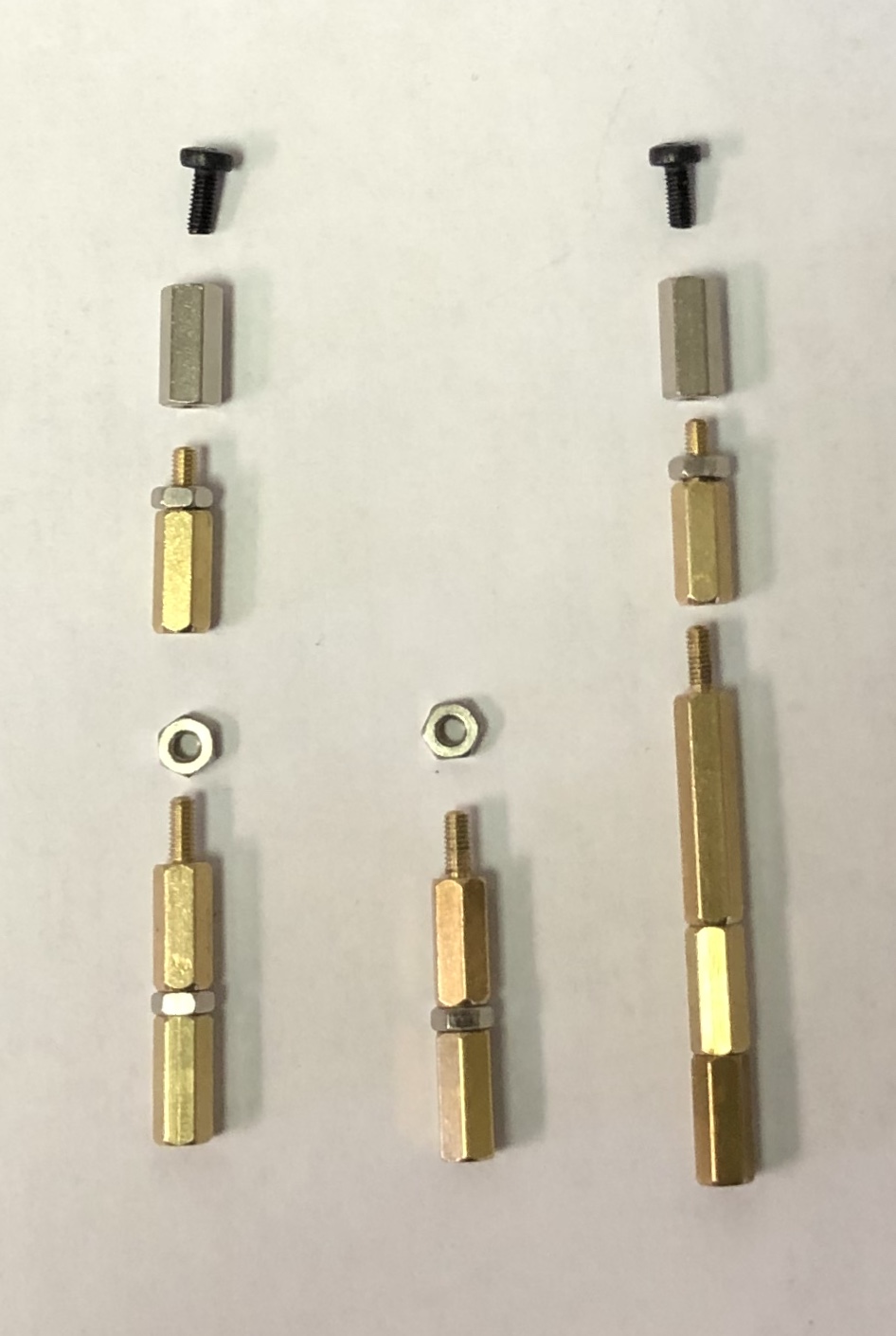
Note, due to differences in the stackable headers, you may require a slightly different set of standoffs. Don't stress the boards trying to make the suggested standoff arrangement work - just modify it so that the boards plug in snugly.
Raspberry Pi Zero W
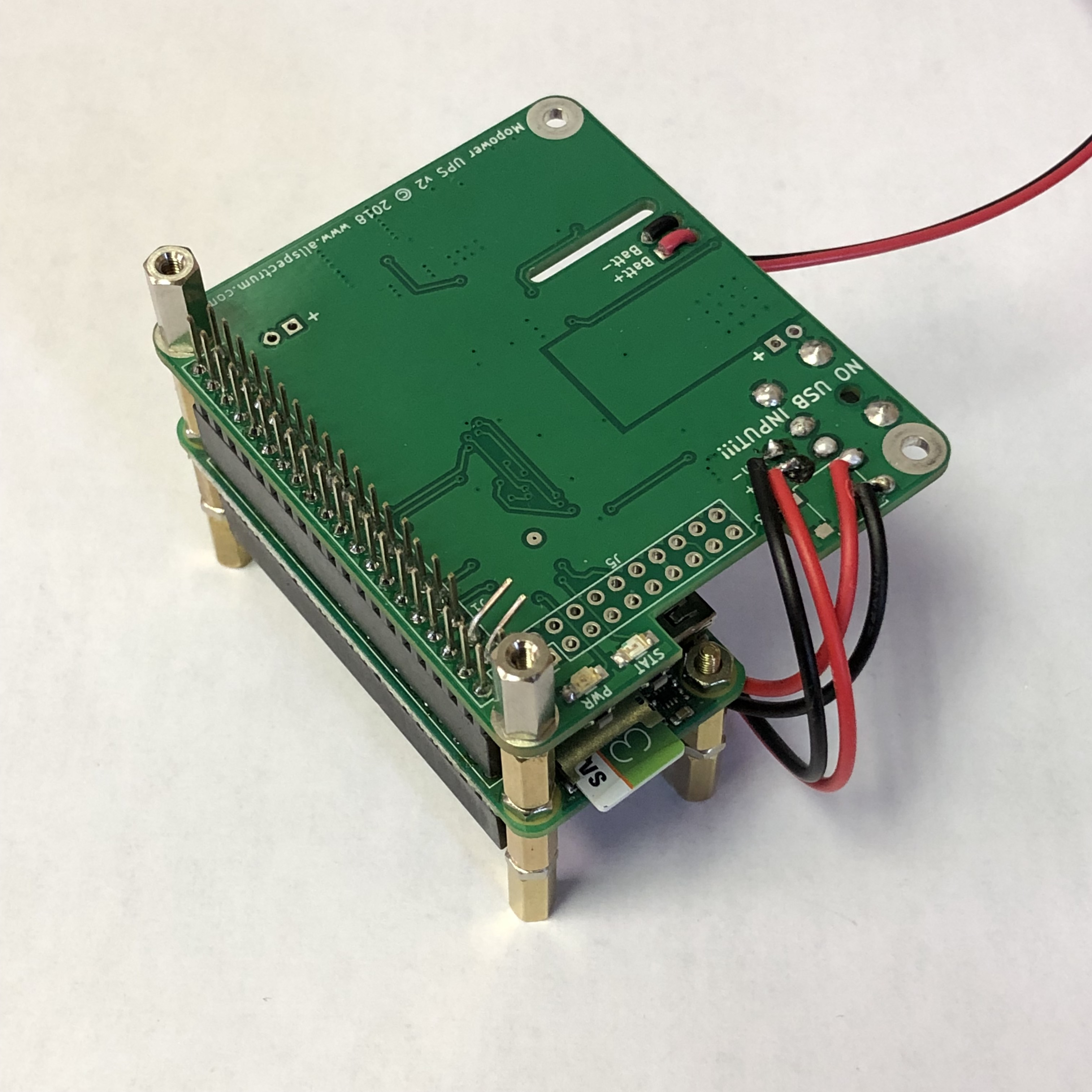
You will need to install the stackable header on the Raspberry Pi Zero W. Make sure you solder it in the right way. Insert the stackable header from the bottom of the Raspberry Pi Zero W board (the side without the chips and other components). Flip the board over and solder the header pins. Be careful not to let the solder climb too high on the header or you may have difficulty plugging the MoPower UPS V2 board into it. The pins should face up when the Pi Zero W board is face up (chips and components on top), as shown here:
Install the 2.5mm standoff hardware (10x 11mm length, 10x nuts) so that the board sits flat and is ready for the next board to plug in, as shown below:
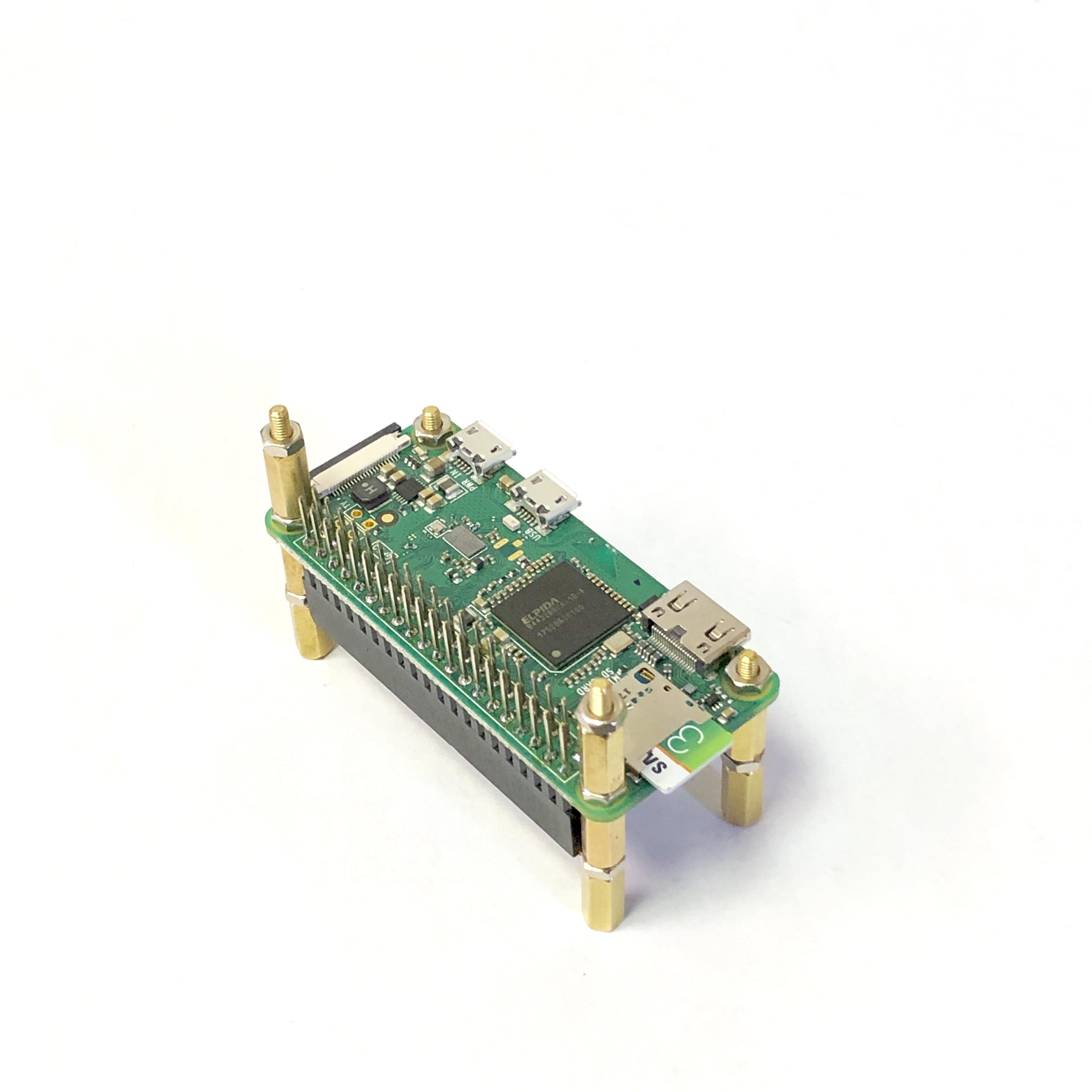
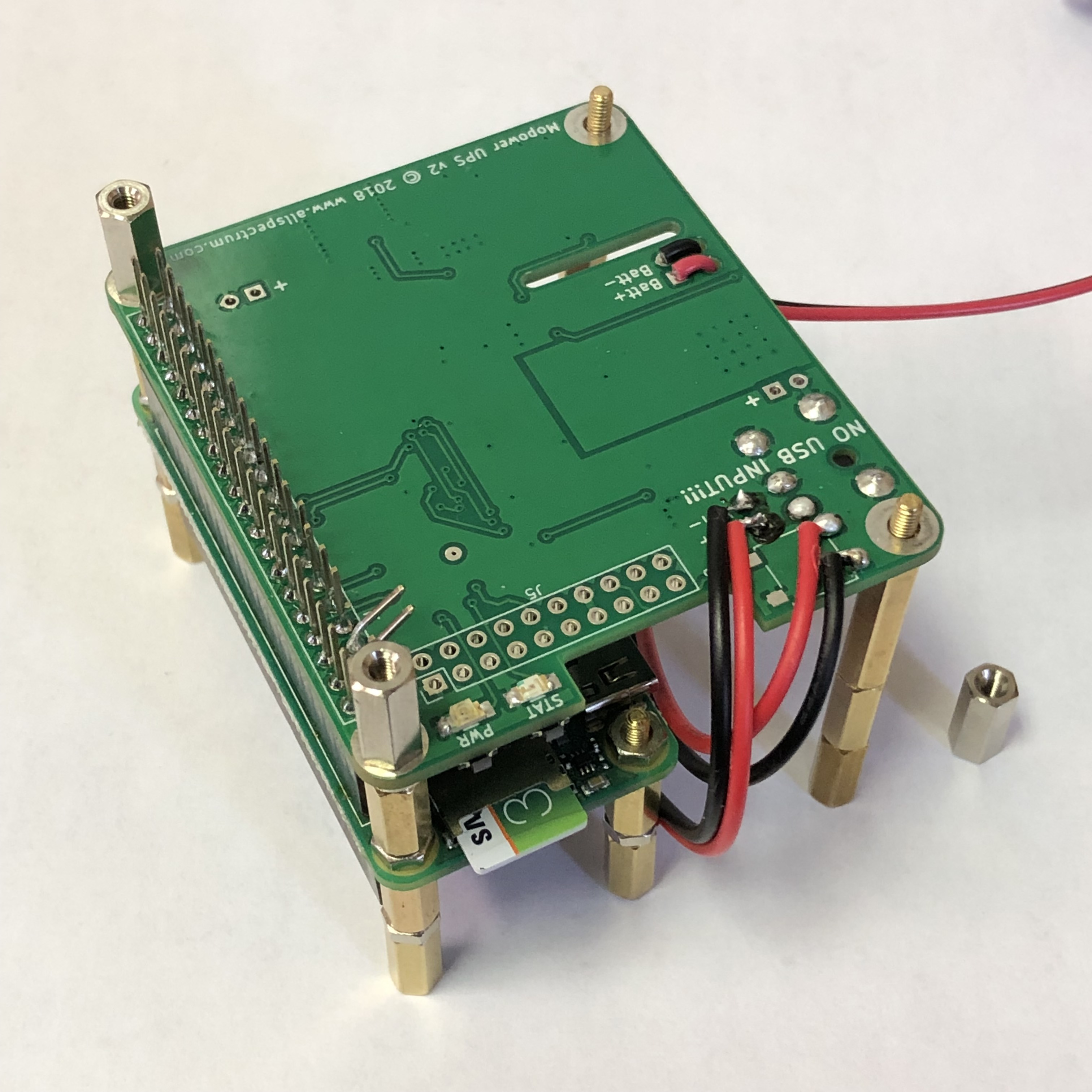
Insert you micro SD card so it is ready to boot when you start the software installation.
MoPower UPS board installation
The MoPower UPS board needs to have a stackable header installed. If you ordered a MoPower UPS board without a GPIO connector, then you are ready to install the stackable header. If your MoPower UPS board has a 2x5 pin GPIO header installed, you will need to carefully unsolder and remove it.
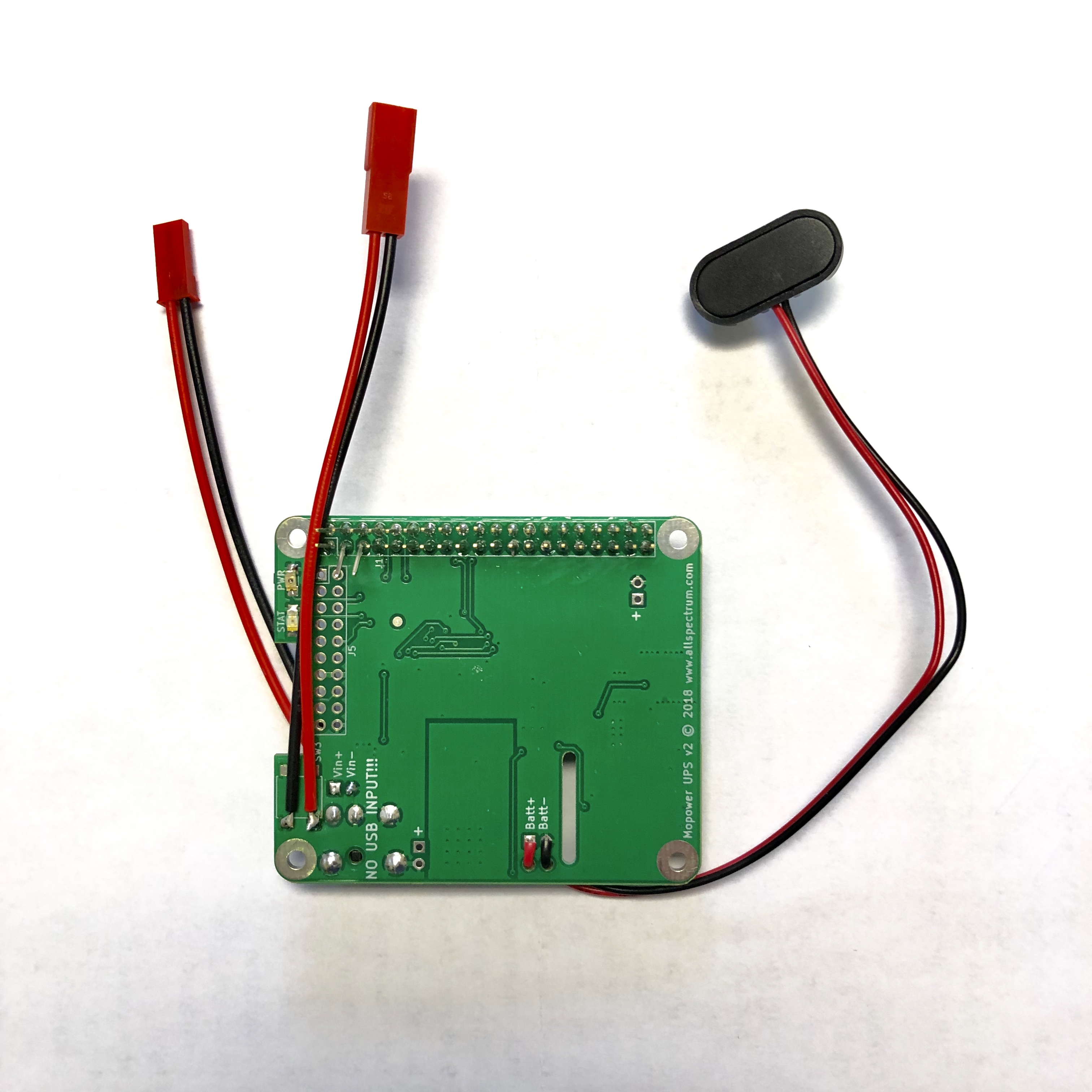
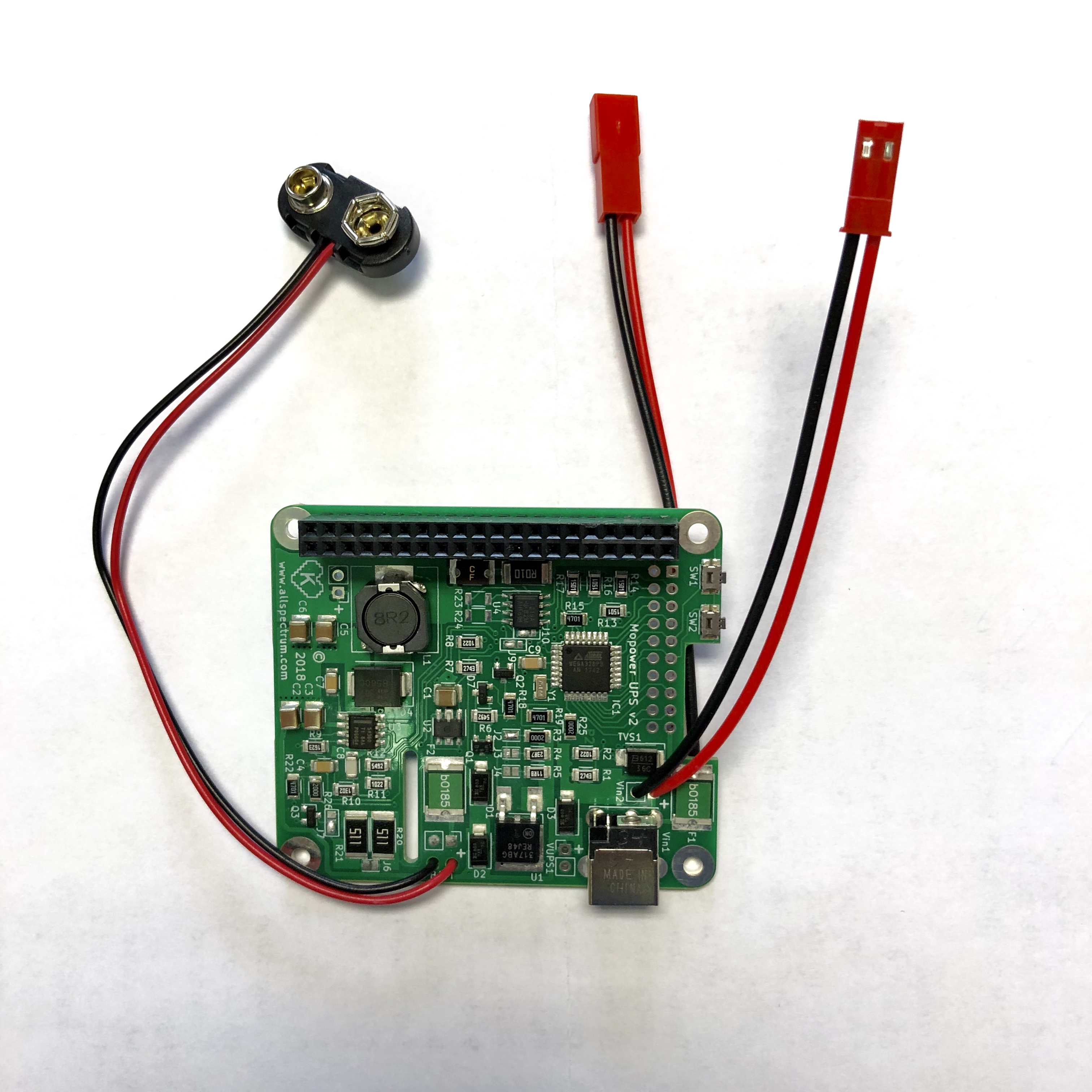
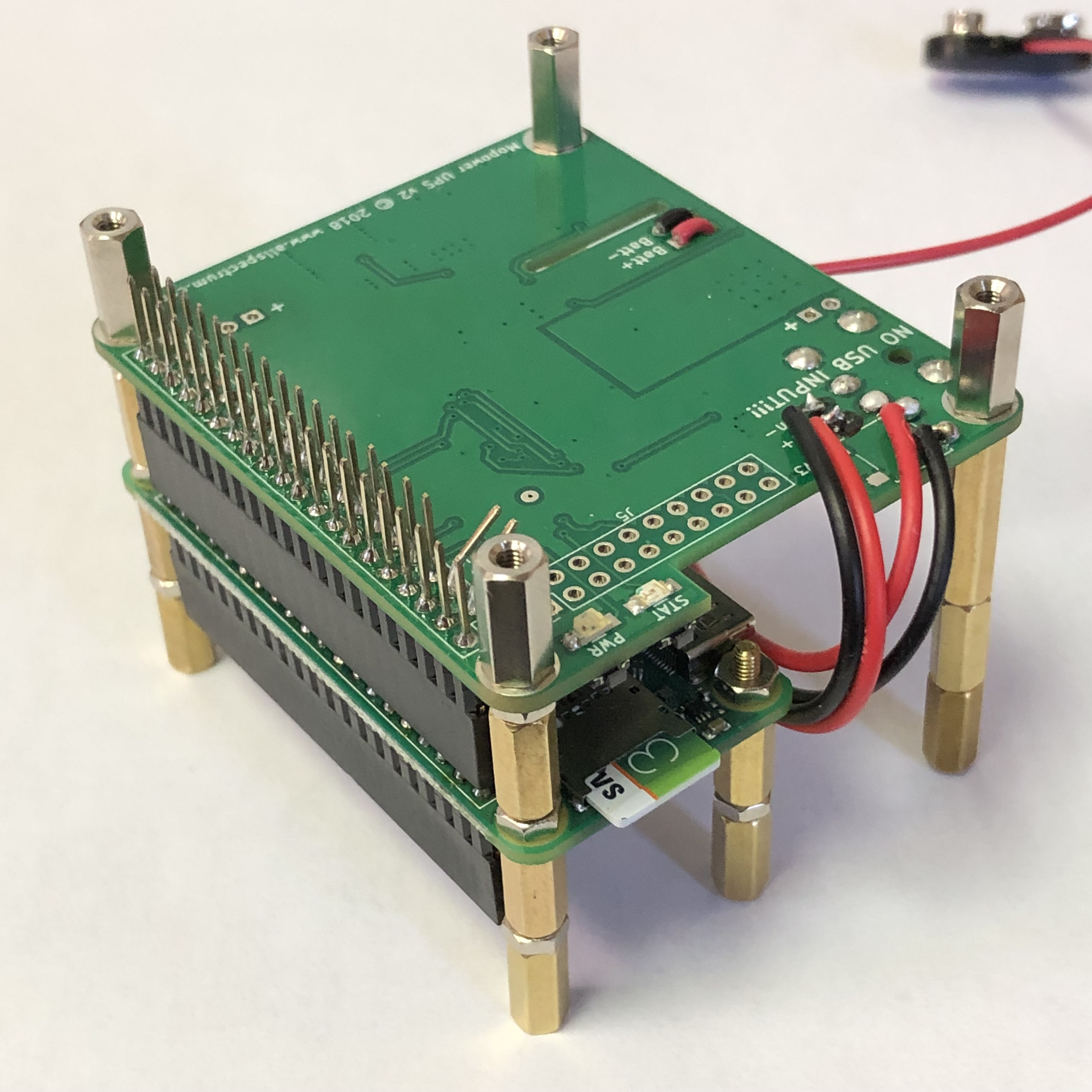
Carefully solder in a 2x20 stackable header. The components on the MoPower UPS V2 board are mounted on the bottom, so the header pins should face down when the MoPower board is face up (chips and components are on the top). Insert the stackable header on the component side of the MoPower board, then flip the board over and solder the pins. It should look like this:
In order to get current telemetry on the CubeSat Sim, you will need to bend two of the GPIO connector pins (pins 3 and 5 see the image below, or use the reference https://pinout.xyz/) on the MoPower UPS board so that when you plug the Digital Transceiver board into it, they do not make contact. If you do not want to bend pins, you just won't get any current telemetry, as shown in the pictures below. If you plan to build the Solar Power Board, then you will need to solder JST RCY connectors to the switch SW3 and Vin2. The switch connector is a male while Vin2 is a female connector, as shown here:
Plug in the modified MoPower V2 UPS board header socket into the Pi Zero W header pins. Install the 2.5mm hardware (2x 11mm fully threaded) so the stack will look like this:
Since the MoPower board is the first full sized board in the stack, you will need to build two legs out of standoffs (2x 20mm, 8x 11mm) as shown:
Finally, install the 2.5mm hardware (2x 11mm fully threaded) so the board is ready for the Digital Transceiver board:
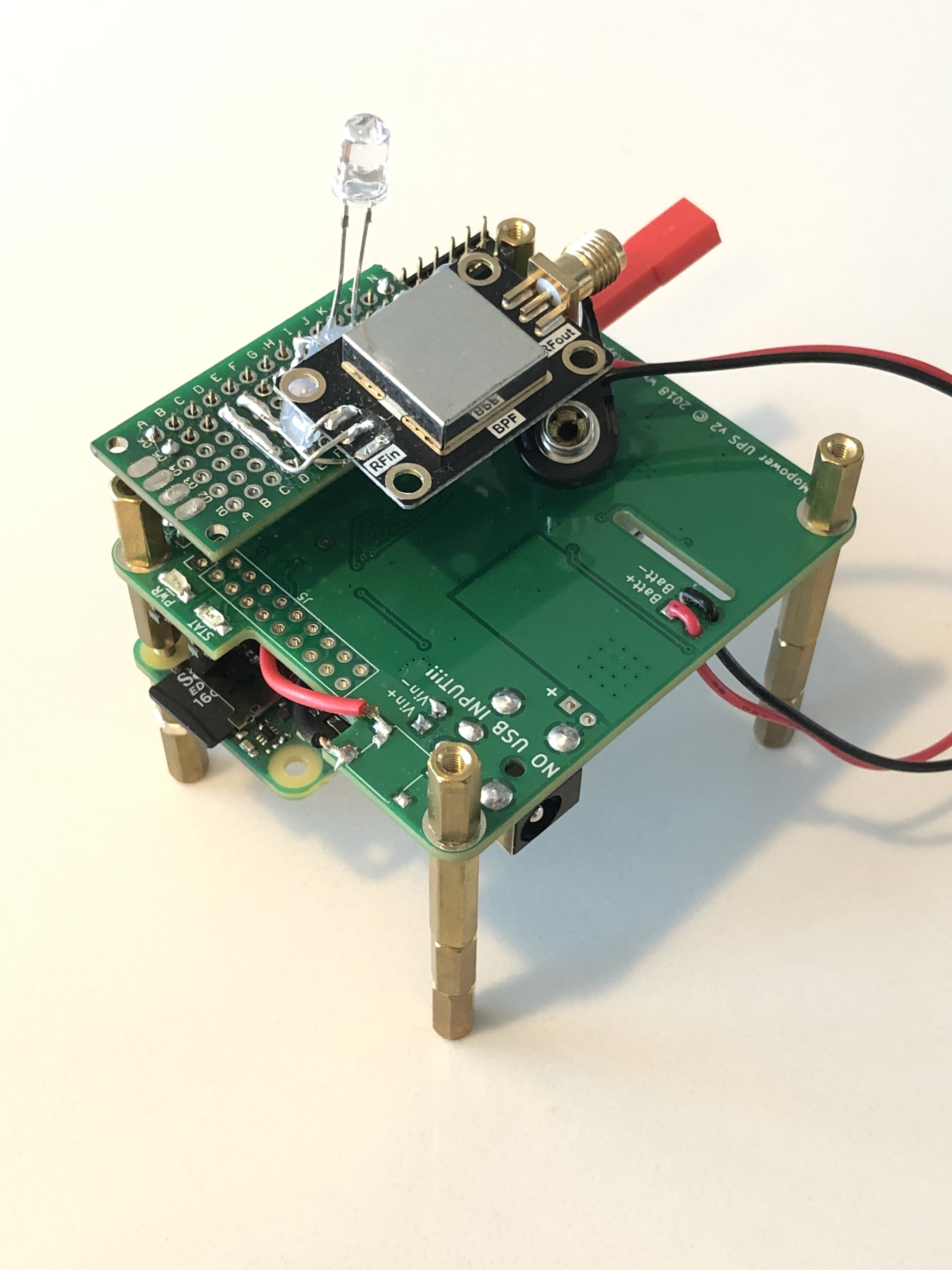
Transmitter/Filter Board
NOTE: These instructions are for the experimental Transmitter/Filter Board instead of the Digital Transceiver Board. If you are using the old Digital Transceiver Board, skip these steps and follow the steps here.
The Transmitter/Filter Board just plugs into the top of the board stack as shown here:
You are now ready to Install the software.
Back to the CubeSat Simulator Home Page.