vB3 Arduino Payload - alanbjohnston/CubeSatSim GitHub Wiki
An Arduino can act as a payload for the CubeSat Simulator.
This is not the latest version of the CubeSatSim. You can find it here.
It can communicate with the Command and Data Handling (C&DH), i.e. the Raspberry Pi CPU, using the I2C bus 0. This bus and 5 V power and Ground are available on the expansion connector J6.
Many different sensors can be interfaced with the Arduino.
First install the Arduino IDE software by following these instructions:
https://www.arduino.cc/en/Main/Software
Next, test your Arduino and your software install by doing the Blink tutorial (use the built in LED so you don't need to wire anything):
https://www.arduino.cc/en/tutorial/blink
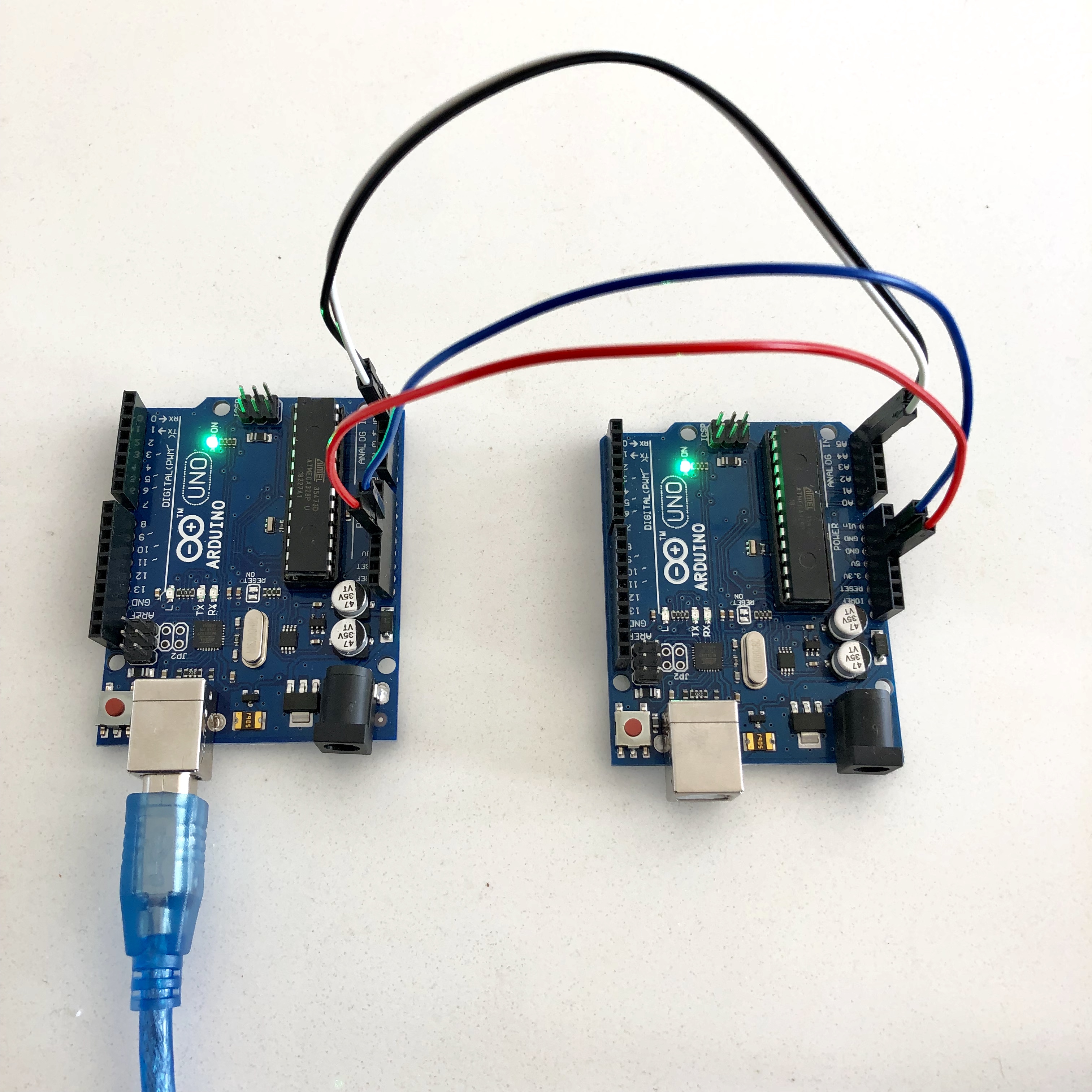
If you have two Arduinos, you can test the I2C interface software by configuring one Arduino as the I2C Bus Master and the other as the I2C Bus Slave. The one Arduino emulates the C&DH (the Raspberry Pi) and the other Arduino is the Payload Subsystem. Here is a tutorial that shows you how to test this:
https://www.arduino.cc/en/Tutorial/MasterReader
Here is some simple code to show I2C register reading by a master from a slave. Using the Serial Monitor in the Arduino IDE over the USB cable, you can monitor the data transmitted over the I2C bus.
https://github.com/alanbjohnston/CubeSatSim/tree/master/arduino
Here is the back-to-back Arduino setup, showing the connections between A4 (data SDA), A5 (clock SCL), GND, and 5V between the two boards.
Your payload software should continually update the sensor information data in the loop() part of the Arduino code.
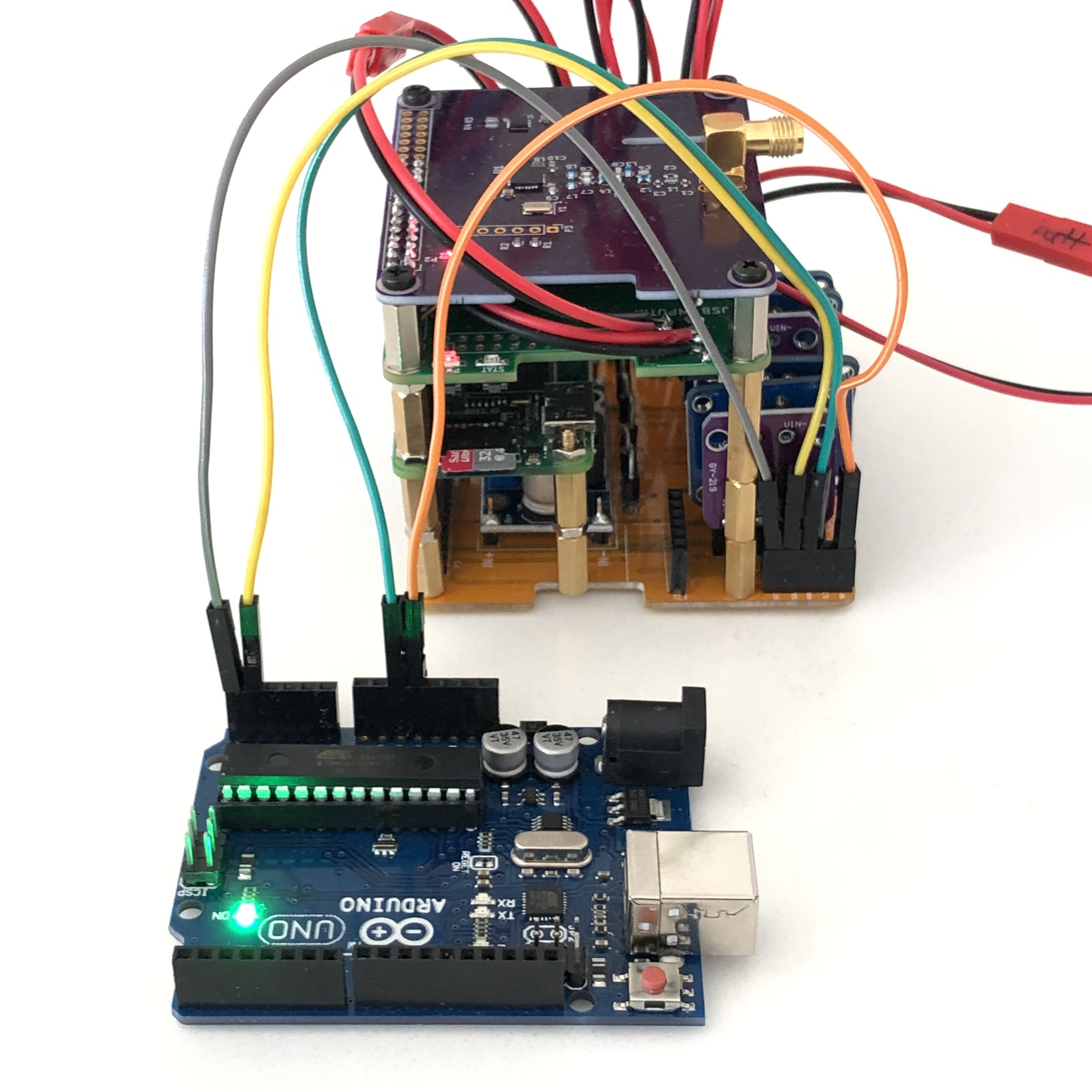
Here is how to connect the Arduino to the CubeSat Simulator using the Expansion Interface J6 connector:
The Simulator code will read from the Arduino on I2C bus 0 address 0x4b and if it gets a reply, it will read four registers from the Arduino and append the values to the end of the telemetry string in hex format. When the Arduino is connected and has suitable slave software, you will see a 4b when you run the command i2cdetect -y 0 command on the Pi to get:
. . 00 01 02 03 04 05 06 07 08 09 0a 0b 0c 0d 0e 0f
00: . . . . -- -- -- -- -- -- -- -- -- -- -- -- --
10: -- -- -- -- -- -- -- -- -- -- -- -- -- -- -- --
20: -- -- -- -- -- -- -- -- -- -- -- -- -- -- -- --
30: -- -- -- -- -- -- -- -- -- -- -- -- -- -- -- --
40: 40 41 -- -- -- -- -- -- -- -- -- 4b -- -- -- --
50: -- -- -- -- -- -- -- -- -- -- -- -- -- -- -- --
60: -- -- -- -- -- -- -- -- -- -- -- -- -- -- -- --
70: -- -- -- -- -- -- -- --
If the sensor is also an I2C device, it can be connected in parallel with the Arduino on the same SCL and SDA pins (don't forget to connect ground and possibly 3.3V or 5V power, too) as long as the address is not 0x40, 0x41, or 0x4b. For example, if the sensor is 0x4c, then when you run the command i2cdetect -y 0 command you will see both the Arduino and the sensor:
. . 00 01 02 03 04 05 06 07 08 09 0a 0b 0c 0d 0e 0f
00: . . . . -- -- -- -- -- -- -- -- -- -- -- -- --
10: -- -- -- -- -- -- -- -- -- -- -- -- -- -- -- --
20: -- -- -- -- -- -- -- -- -- -- -- -- -- -- -- --
30: -- -- -- -- -- -- -- -- -- -- -- -- -- -- -- --
40: 40 41 -- -- -- -- -- -- -- -- -- 4b 4c -- -- --
50: -- -- -- -- -- -- -- -- -- -- -- -- -- -- -- --
60: -- -- -- -- -- -- -- -- -- -- -- -- -- -- -- --
70: -- -- -- -- -- -- -- --
The code i2c_slave_with_sensor_reading.ino sketch has placeholders for reading the sensor.