v1.1 7. Main Board 3 - alanbjohnston/CubeSatSim GitHub Wiki
You are now ready to complete building and test the Main board.
You will need these tools:
- Safety glasses (to protect eyes while soldering or trimming leads)
- Soldering iron and solder (I use lead-free solder, but leaded solder is easier to work with)
- Needle nose pliers (to bend leads and hold parts)
- Side cutters (to trim leads)
- Drill and drill bits (if you are building the tape measure antenna or want to mount the Remove Before Flight keychain)
Other tools that are helpful:
- USB power meter (to monitor the power draw of your Pi or the charging circuit)
- Blue mounting putty (to hold components in place while soldering)
The first part of this step is testing, the second part continues the build and finishes the board.
Checklist
The BOM has a sheet "By Steps" which lists the parts needed for each step in order. http://cubesatsim.org/bom If you have a Google account, you can make a copy of this spreadsheet ("File" then "Make a Copy") and check off each part as you install it.
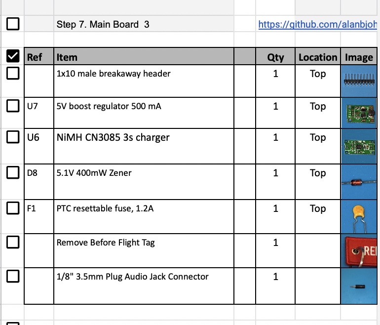
For example, here is the checklist for this step:
Testing
Here is a video of the first set of testing in this step: https://youtu.be/WbL-M7UtvY8
5V Bus Voltage Sensor Test
You can now test the INA219 Current and Voltage (I/V) sensors. You can test them either using your Ground Station with FoxTelem or by typing in commands after logging into your Pi, as described in the Software Install page.
Plug your Pi Zero into the Main board and connect the micro USB power cable to the Pi Micro USB connector to power it as shown here:
To use your Ground Station, run FoxTelem with the RTL-SDR and antenna plugged in, and verify you are receiving a signal from your CubeSatSim.
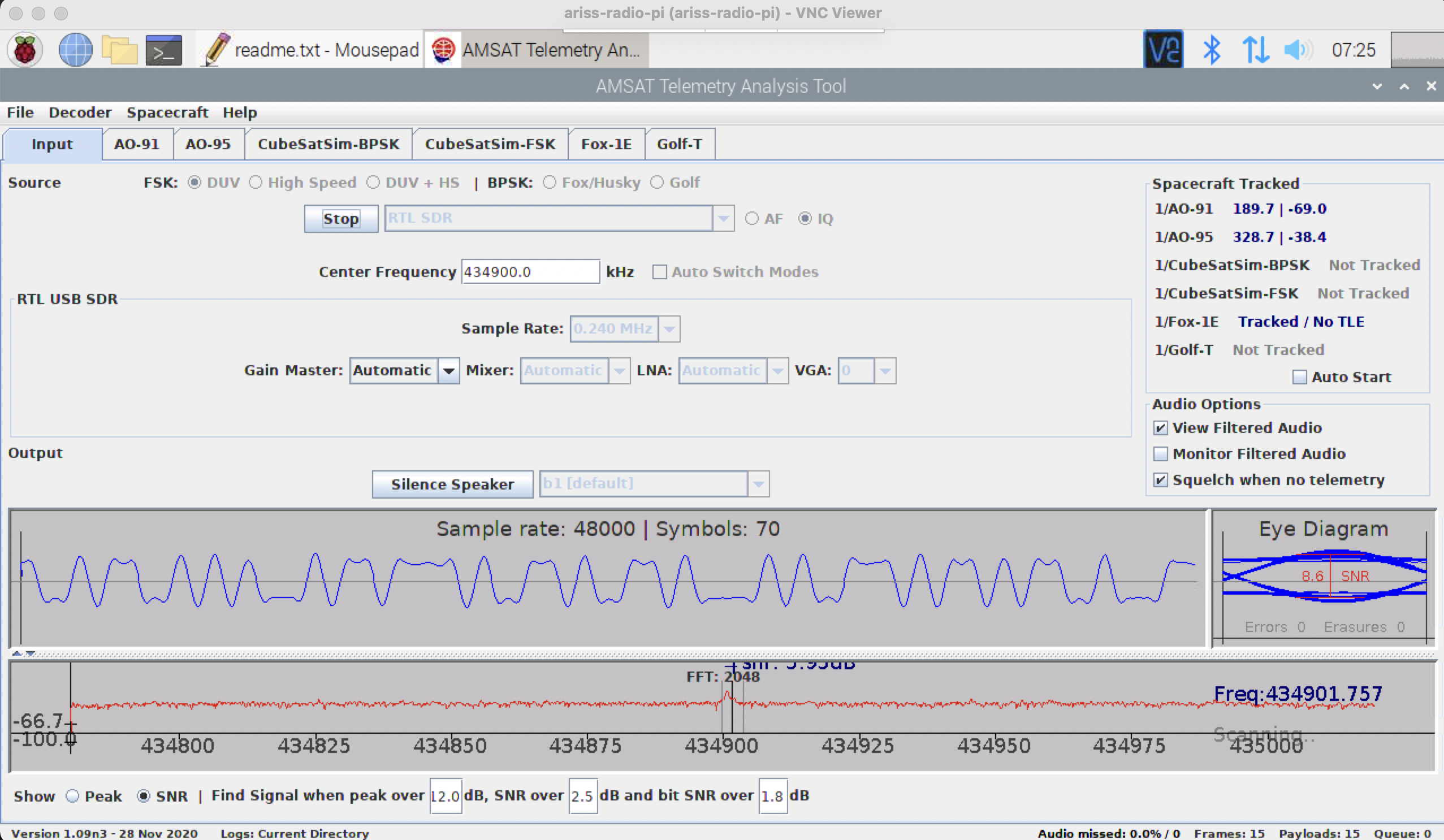
If you don't see the frame count increasing every four seconds or so, check your Ground Station setup or switch to the Pi command line method.
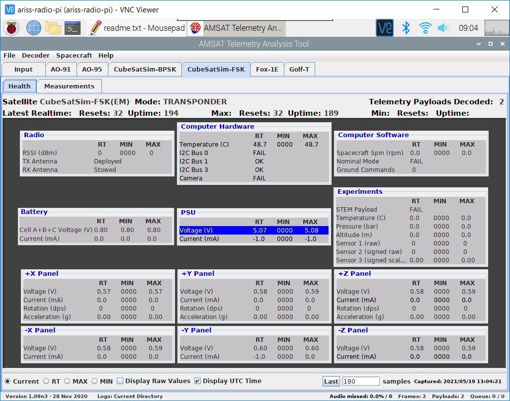
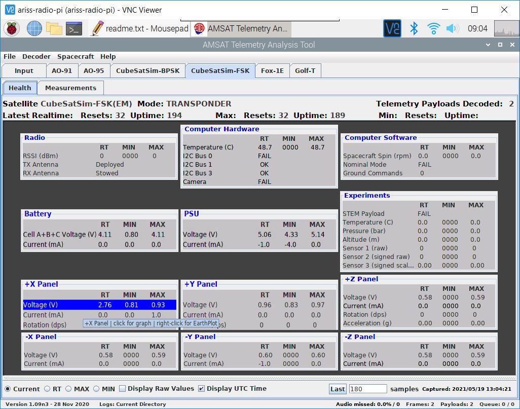
Once you are receiving frames from your CubeSatSim, click on the CubeSatSim-FSK tab which will display the Health tab. If you have received telemetry from your CubeSatSim, you will see non-zero values. Look under box labeled PSU (Power Supply Unit) and you should see approximately 5 Volts:
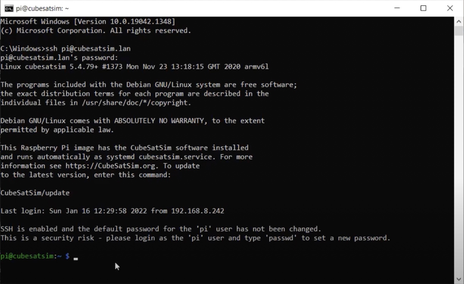
To use the Pi command line method, you will need to be type commands into your Pi. If you have an HDMI monitor connected via a mini-HDMI to HDMI adapter, and a keyboard connected via a micro USB to USB adapter (OTG cable), you can type the commands on the keyboard. If your Pi is on your WiFi network, you can SSH into the Pi and login. If you have a Pi Zero, you can SSH via the USB cable. You will see this after you are logged in (the default Raspberry Pi username is pi and the default password is raspberry unless you changed yours:
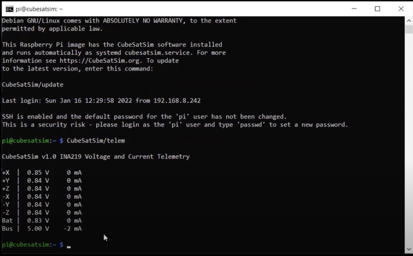
Type this command into the terminal window then hit Return:
CubeSatSim/telem
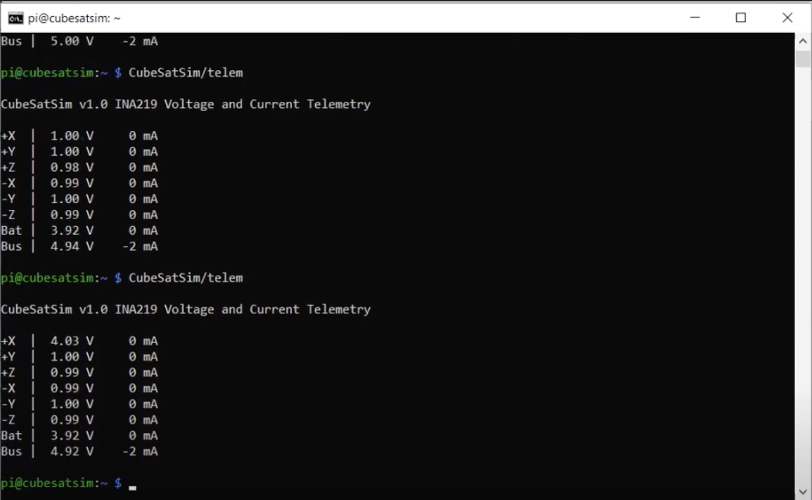
You should see a non-zero voltage for each I/V Sensor that is installed and a voltage close to 5V for the Bus as shown below. The current will read close to zero since you are powering the Pi directly, not through the Main Board:
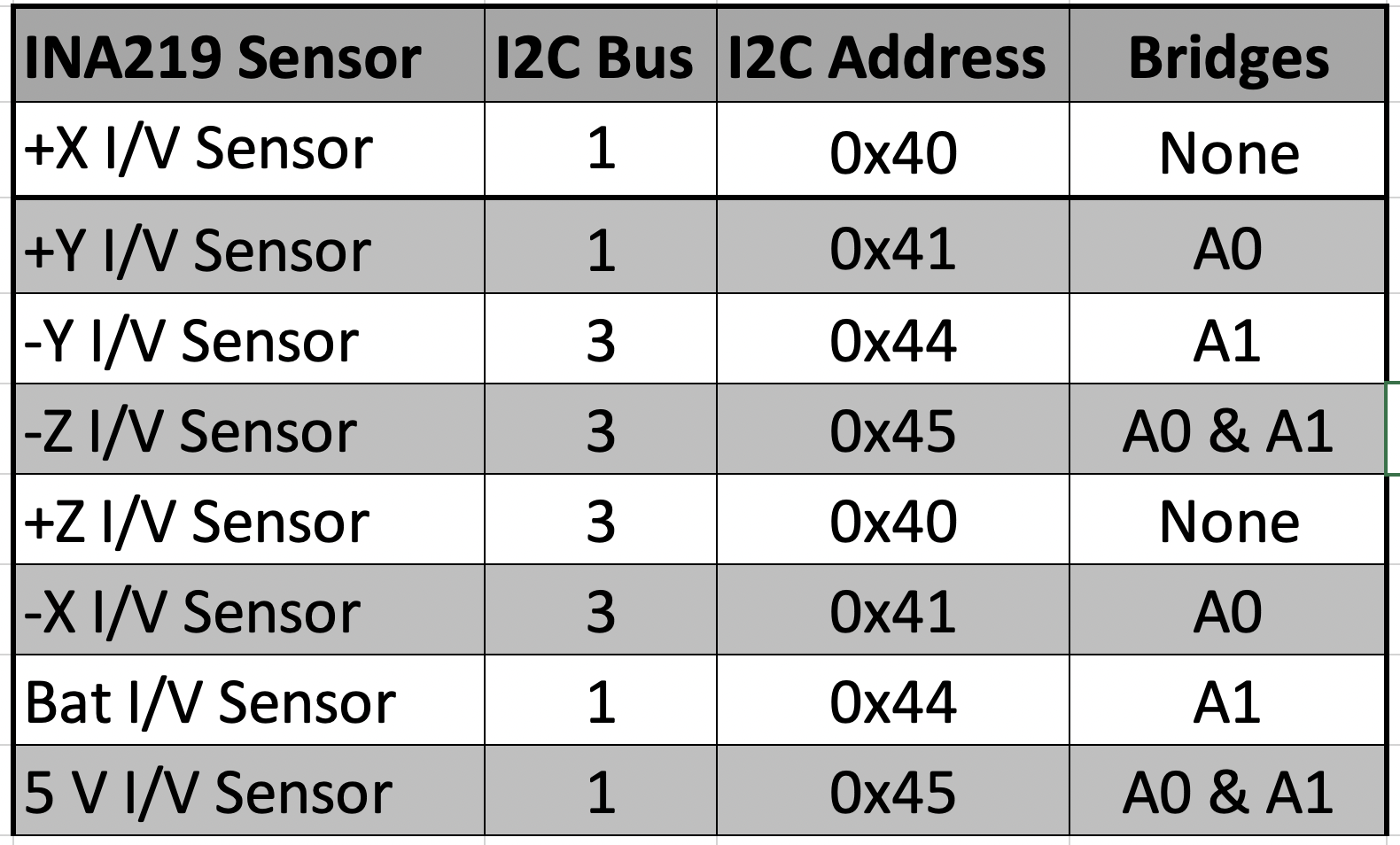
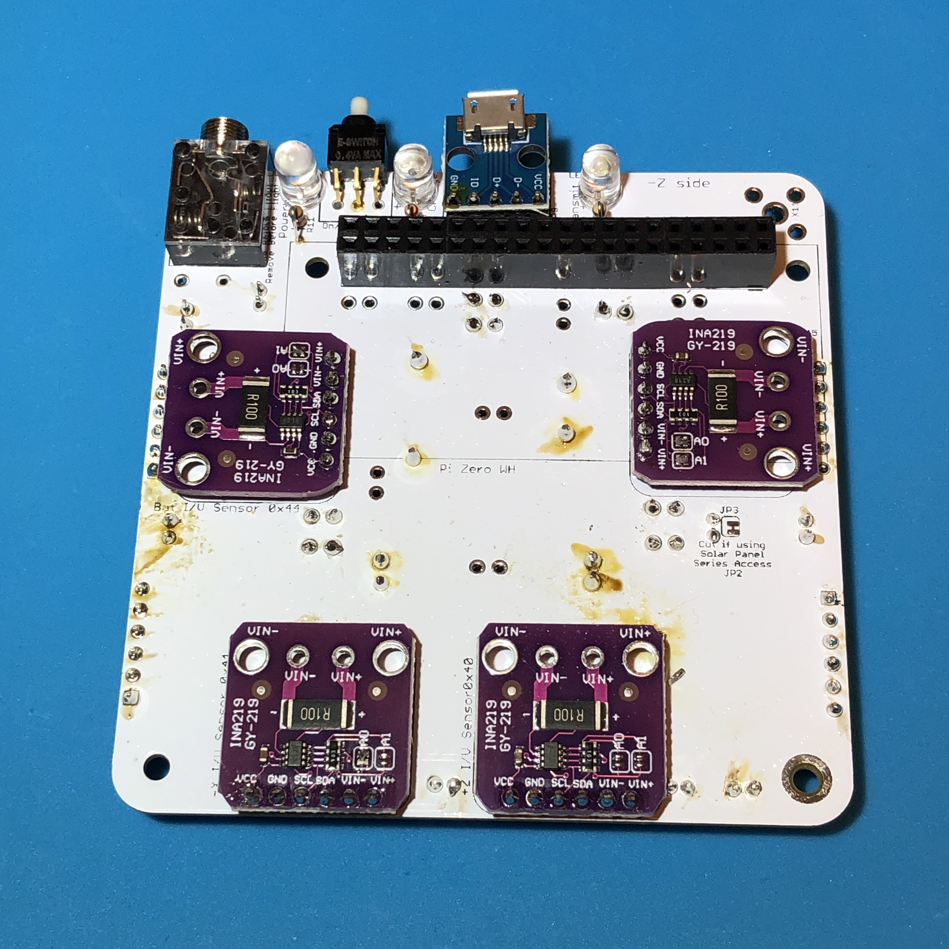
If you don’t get a voltage in FoxTelem or on the command line, there might be a problem with the 5V Bus I/V Sensor such as the wrong address jumper setting on an INA219 board. If you get any errors displayed, there might be a problem with the I2C bus 1. Check the resistors R3 and R4. Also, check the address jumpers A0 and A1 of your INA219 boards. The 5V board is on the bottom of the PCB on the top right side, which should have the address 0x45 or both A0 and A1 bridged.
Here is a table of the I2C sensors on the Pi with the bus number (either 1 or 3) and the address, which is set by the A0 and A1 jumpers:
Battery Voltage Sensor Test
If your Battery Board is built, you can test the Battery I/V sensor by carefully plugging the battery connector into the Main board connector JP10.
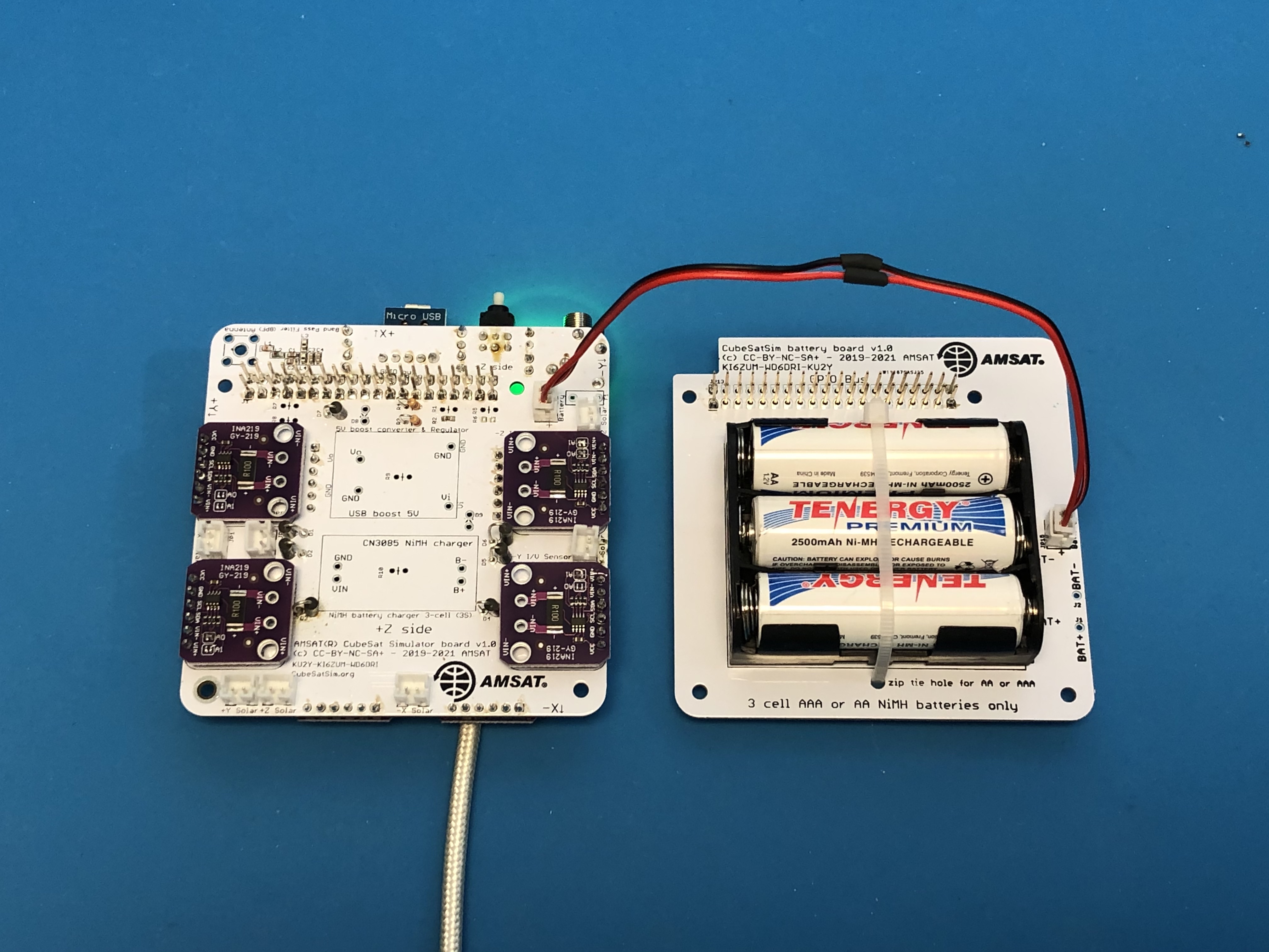
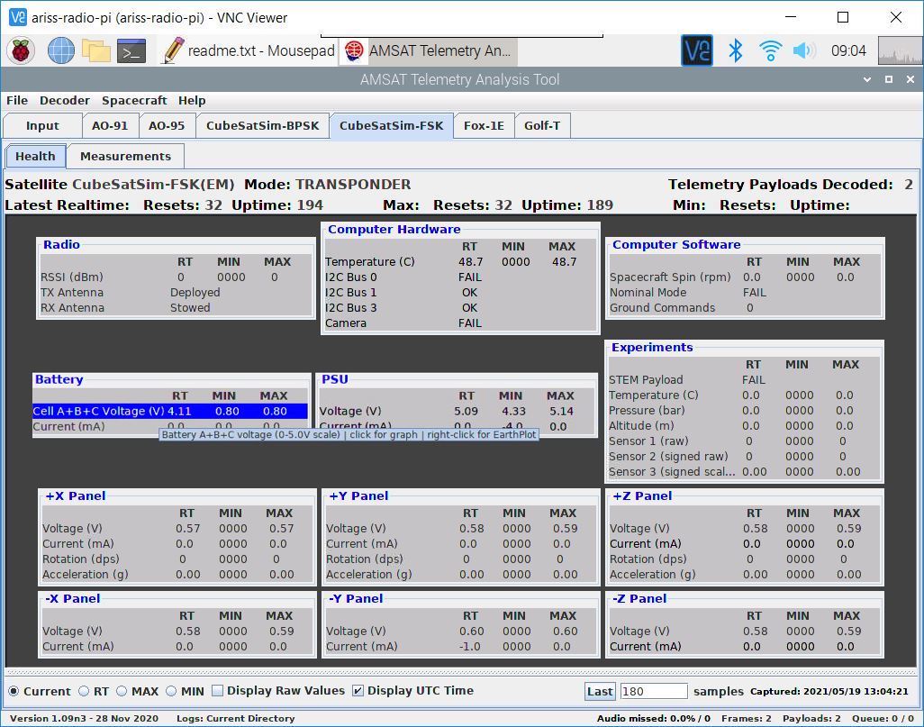
Assuming you are still receiving frames from your CubeSatSim, under the CubeSatSim-FSK tab, look under box labeled Battery and you should see a voltage between 3 and 4.5 Volts:
If you are using the command line, in the terminal window in the Pi, again type:
CubeSatSim/telem
and you should see a non-zero voltage for each I/V Sensor that is installed and a voltage for the Battery between 3V and 4.5V. For example, this shows all six I/V Sensors installed and a battery plugged in.
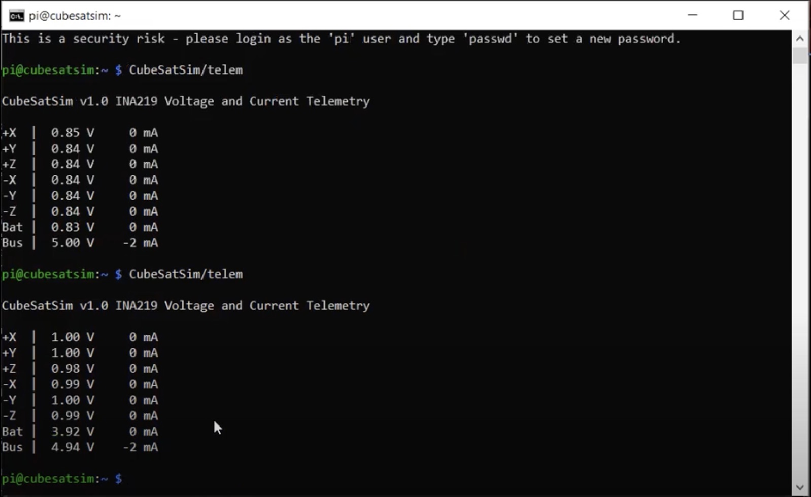
The current will read zero since you are powering the Pi directly, not through the Main Board.
If you don’t get a voltage for your battery, there might be a problem with the Battery I/V Sensor which is on the bottom of the board on the top left with address 0x44, jumpers A1 bridged and A0 no jumper. Or, there might be a problem with your Battery Board such as an incorrect wiring or polarity, or a battery cell popped out or reversed.
Solar Panel Voltage Sensor Test
To test the solar panels, you need to have at least one solar panel and cable soldered up. You will need your Pi with the micro SD card with the CubeSatSim software, your Main board, a Solar Panel and JST cable (a JST 2.0 cable soldered red to red and black to back to a JST RCY cable). The Battery board can be either plugged in or unplugged.
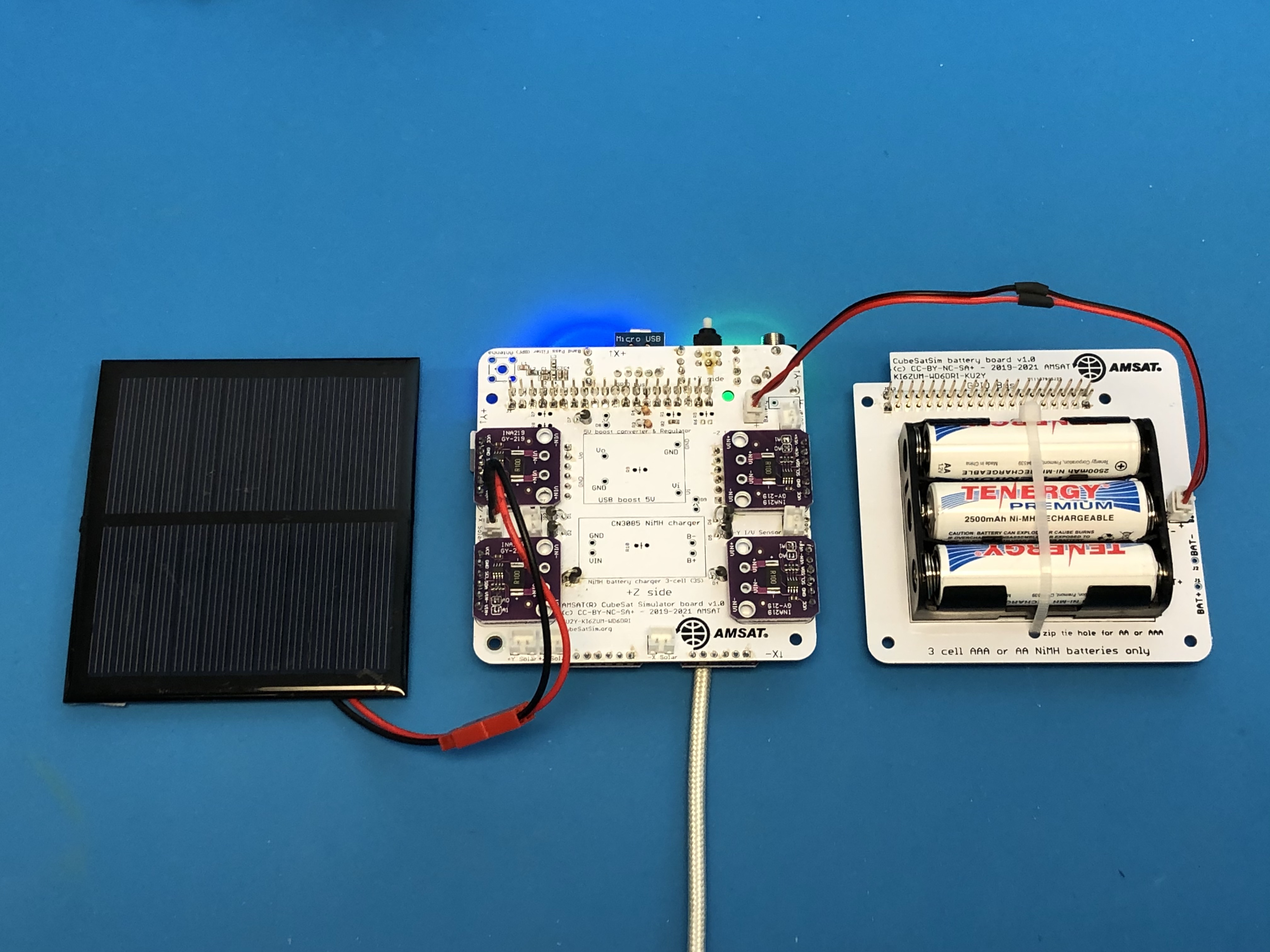
With the Pi plugged into the Main board and the power cable plugged into the Pi micro USB port, after booting, the CubeSatSim software will run. Plug the Solar Panel into the JST cable and plug the cable into the Main board into the +X Solar JST connector (left side of PCB) connector JP1.
If you are still receiving frames from your CubeSatSim, under the CubeSatSim-FSK tab, look under box labeled +X Panel and you should see a voltage greater than 1.5 Volts:
If using the command line method, open a terminal window in the Pi and type:
CubeSatSim/telem
and you should see a non-zero voltage for each I/V Sensor that is installed. If you have a Solar Panel plugged into an I/V sensor and it is illuminated, you should see a voltage greater than 2V. For example, this shows only the +X I/V Sensor installed and a Solar Panel plugged into it:
If you don't see a voltage for the +X Solar Panel, check the wiring on your solar panel and make sure it is plugged into the +X Solar JST connector.
You can move your solar panel connection around to all the connections to test them such as -X, +Y, -Y, +Z, and -Z.
If you see an error displayed, the I2C configuration on the Pi might be incorrect. If you don’t get a voltage, there might be a problem with the I/V Sensor such as the wrong address setting.
If you have your Ground Station running, you can restart your CubeSatSim by pressing and releasing the pushbutton. When you start the DUV telemetry decoding in FoxTelem, you can see the individual solar panel voltages in the Health tab.
Assembly
Video
Here is a video of the assembly part of this step: https://youtu.be/IhlVsJ3hm40
Finishing the Main Board - Battery charging circuit
Shut down your Pi by typing:
sudo shutdown now
Or by pressing and holding the pushbutton until the green LED blinks slowly. Then, unplug the Pi from the Main board and unplug the Battery board and any solar panels.
Next, we will install the 5V boost converter board and the NiMH battery charging board. The 5V boost converter increases the battery voltage from 3 - 4.5V to the 5V that the Raspberry Pi needs. The NiMH charger board is used to regulate the charging for the three Nickel Metal Hydride batteries from the micro USB cable.
Cut four individual 1x1 pin headers and two 1x2 pin headers, and insert into the top of the PCB (do not solder yet) for the 5V boost converter board and NiMH charger board as shown here:
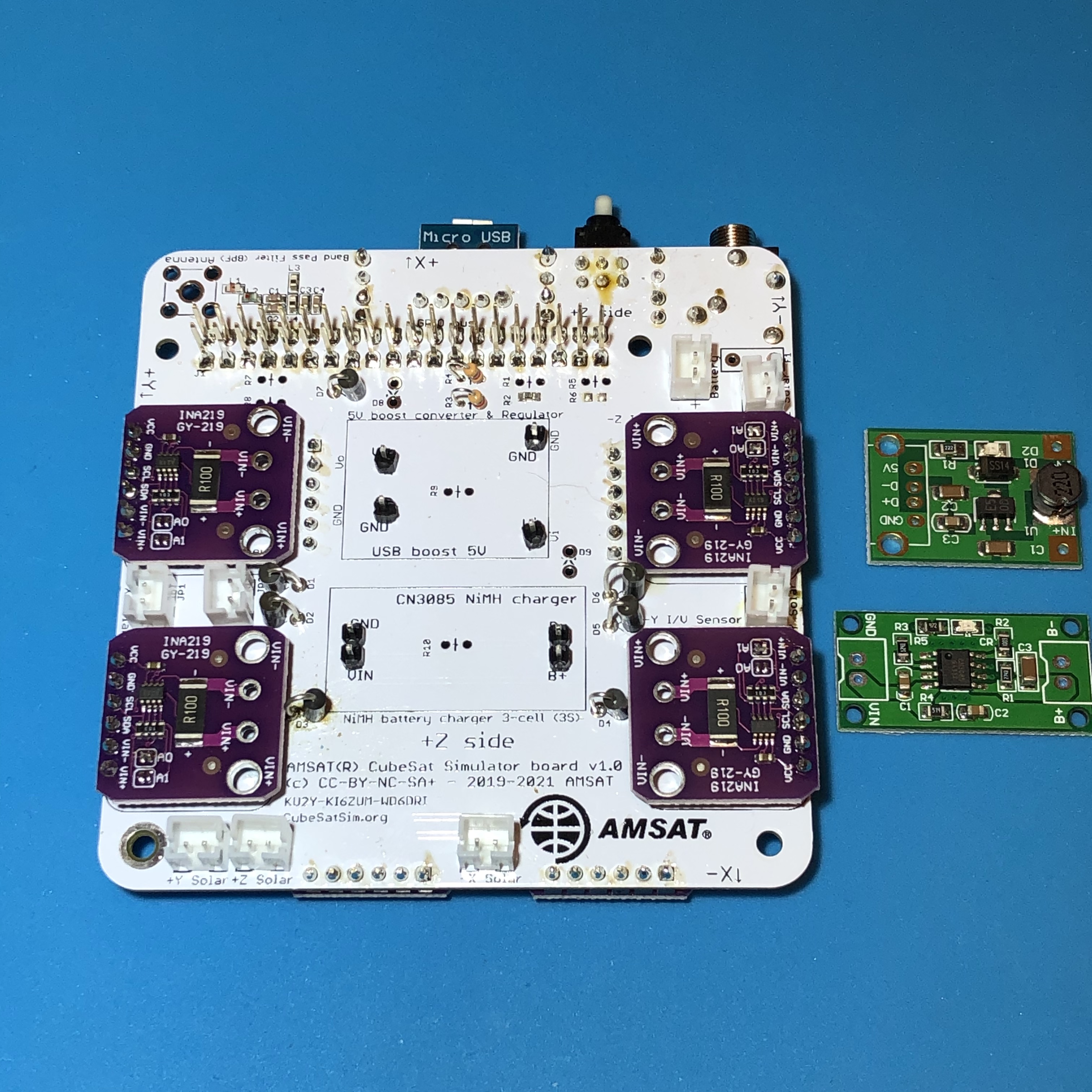
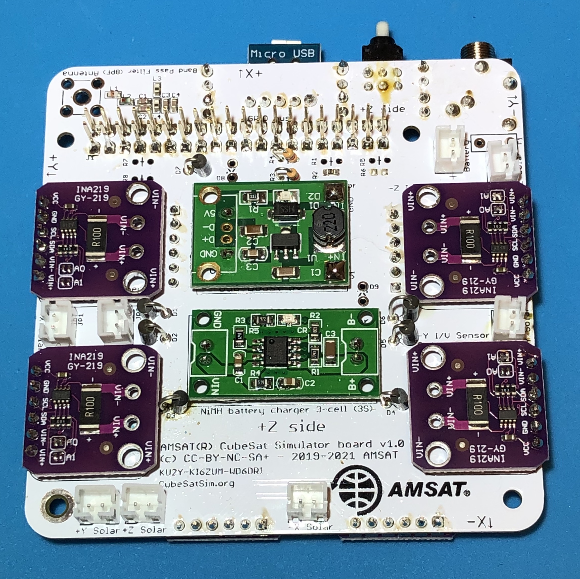
Then, place the 5V boost converter board and NiMH charger board on the pins. The 5V boost converter can only go one way, but make sure the NiMH charger board is the right way: the pins for GND and VIN should be on the left, and the pins for B- and B+ should be on the right, when the PCB is placed as shown in this photo.
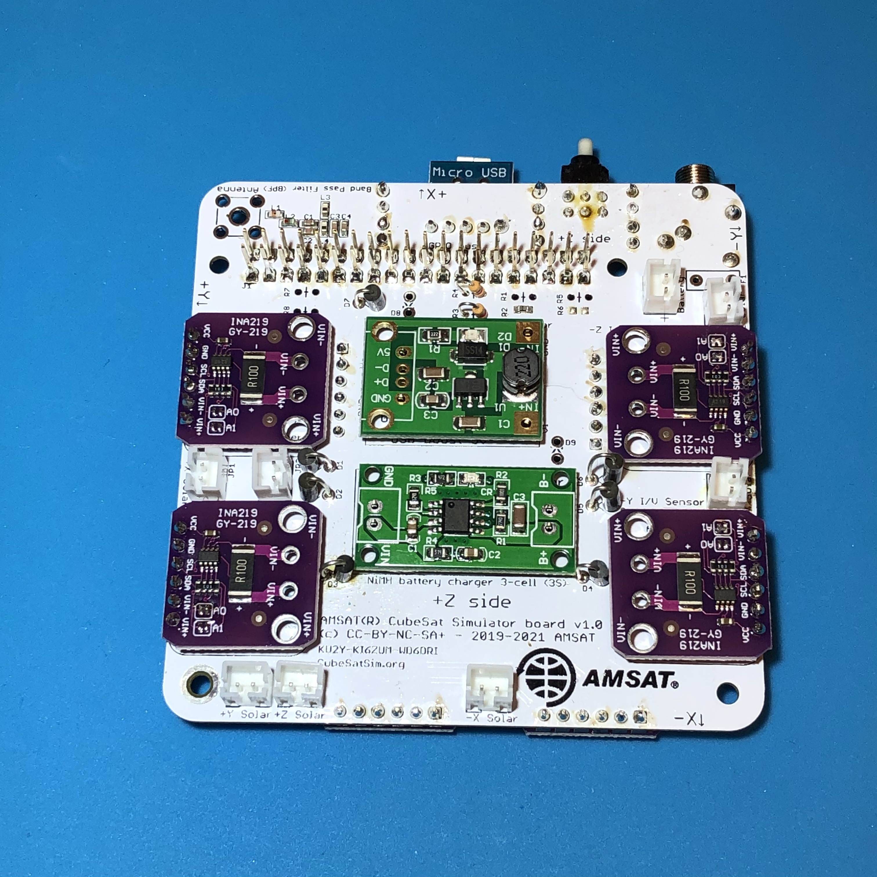
Solder the top of the pins to the boards:
Then turn the PCB over and solder the pins to the bottom of the PCB.
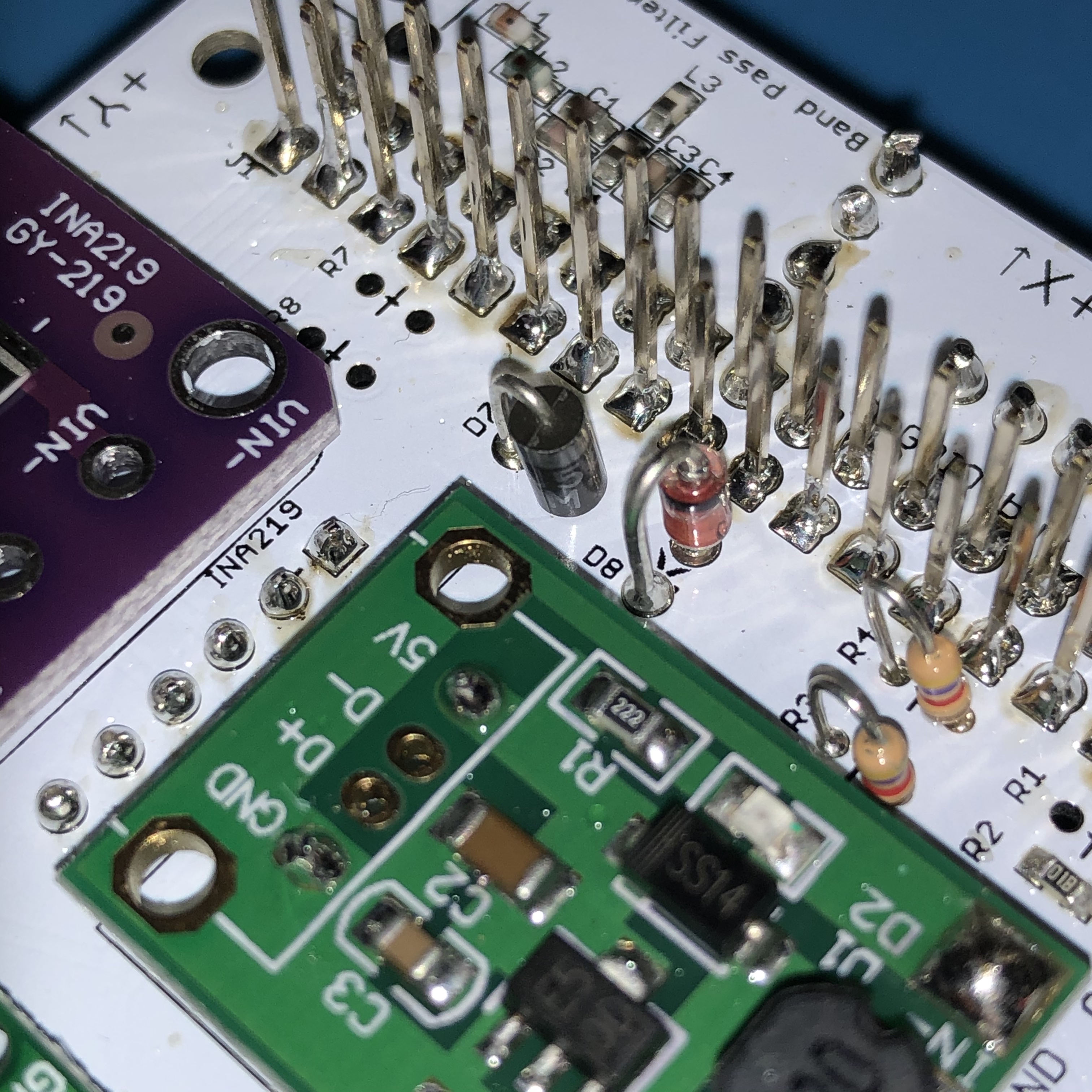
The final components are the zener diode D8 and the PTC resettable fuse F1. The zener diode has a clear case and a black stripe on one lead to indicate polarity. (Don't confuse this zener diode D8 with diode D4 from the STEM Payload board. They look similar, but this zener D8 will have "5V1" written on it since it is a 5.1V zener diode while the diode D4 from the STEM Payload board will have "41" and "48" written on it since it is a 1N4148 diode) The zener protects the charging circuit from a voltage higher than 5.1 Volts. The PTC resettable fuse protects the circuit from over current, limiting the output to 1.2 Amperes. It looks a little like a capacitor, but it has the lettering "0120 RG" on it.
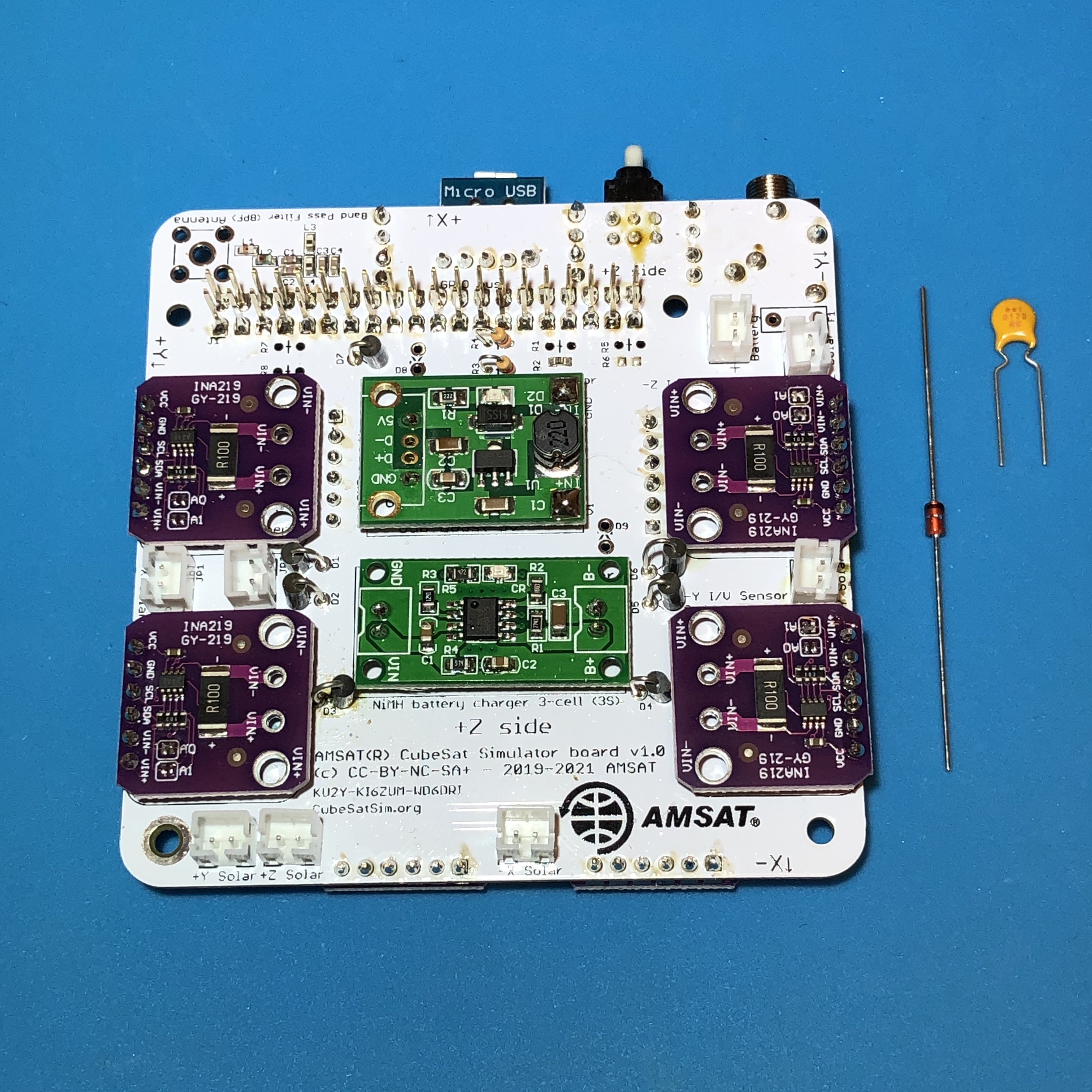
The PTC does not have a polarity, but the zener has a polarity on it with a black stripe which should be installed as shown here:
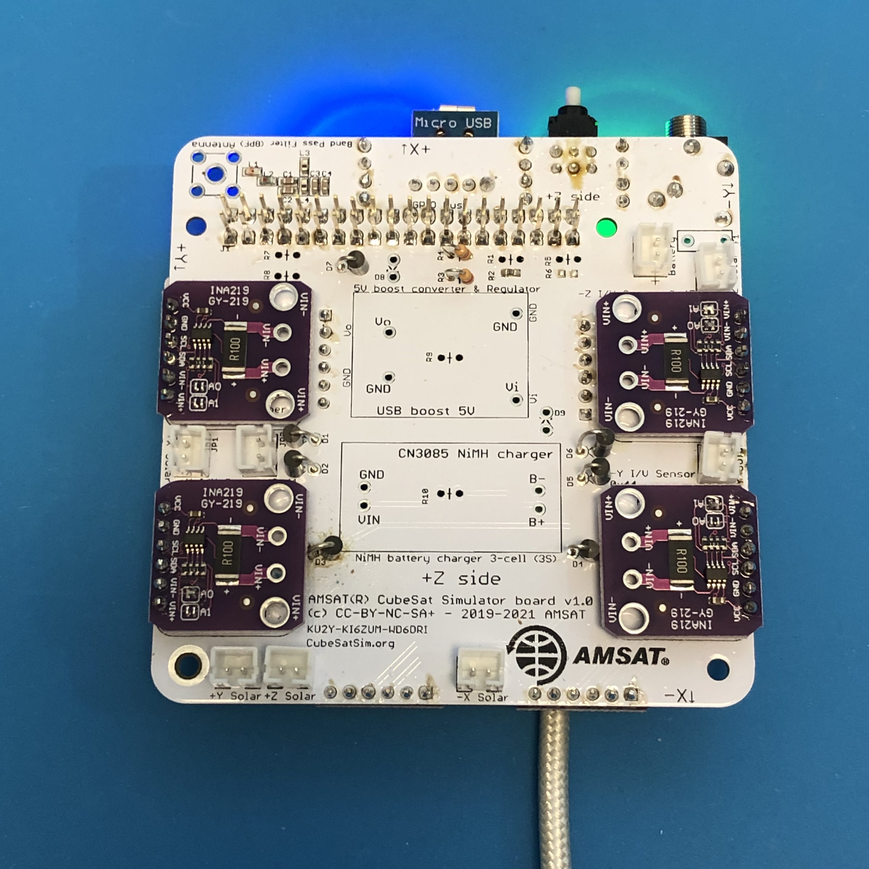
Here is the finished PCB with the zener and fuse installed:
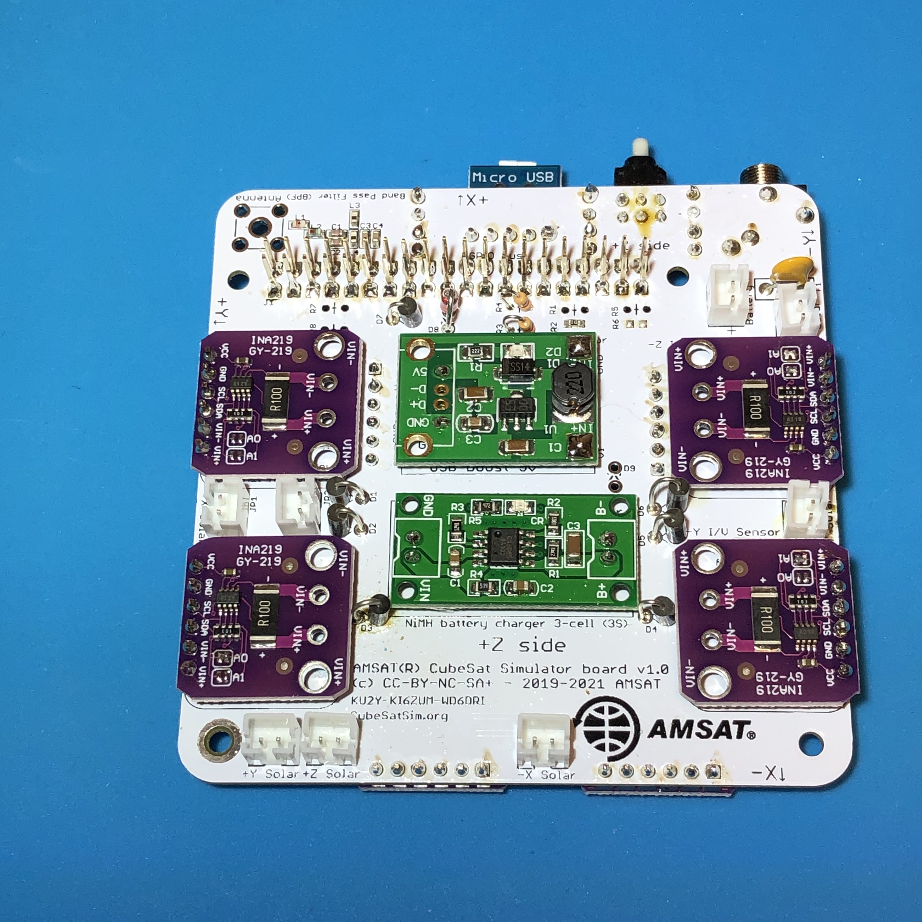
The main PCB is now complete!
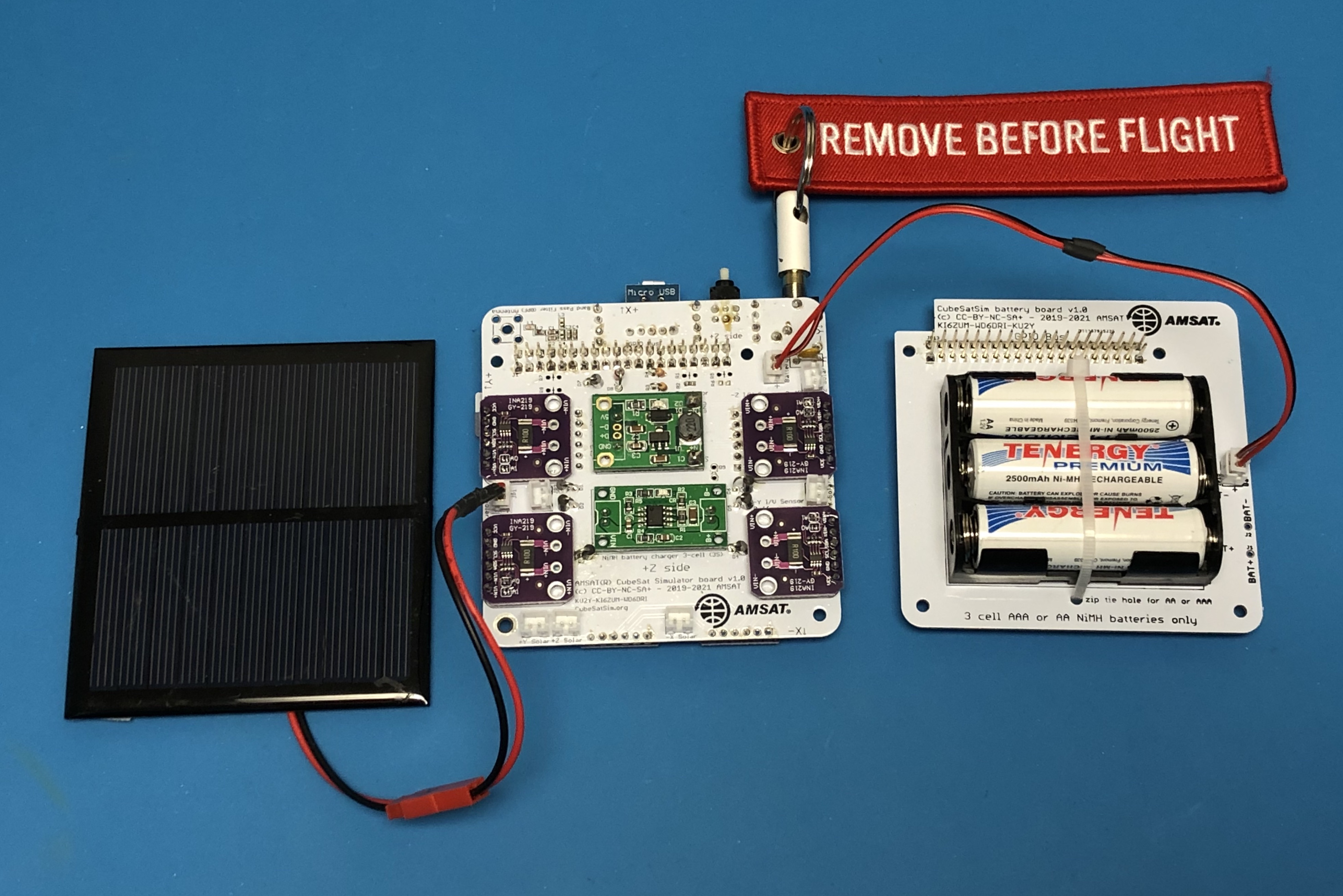
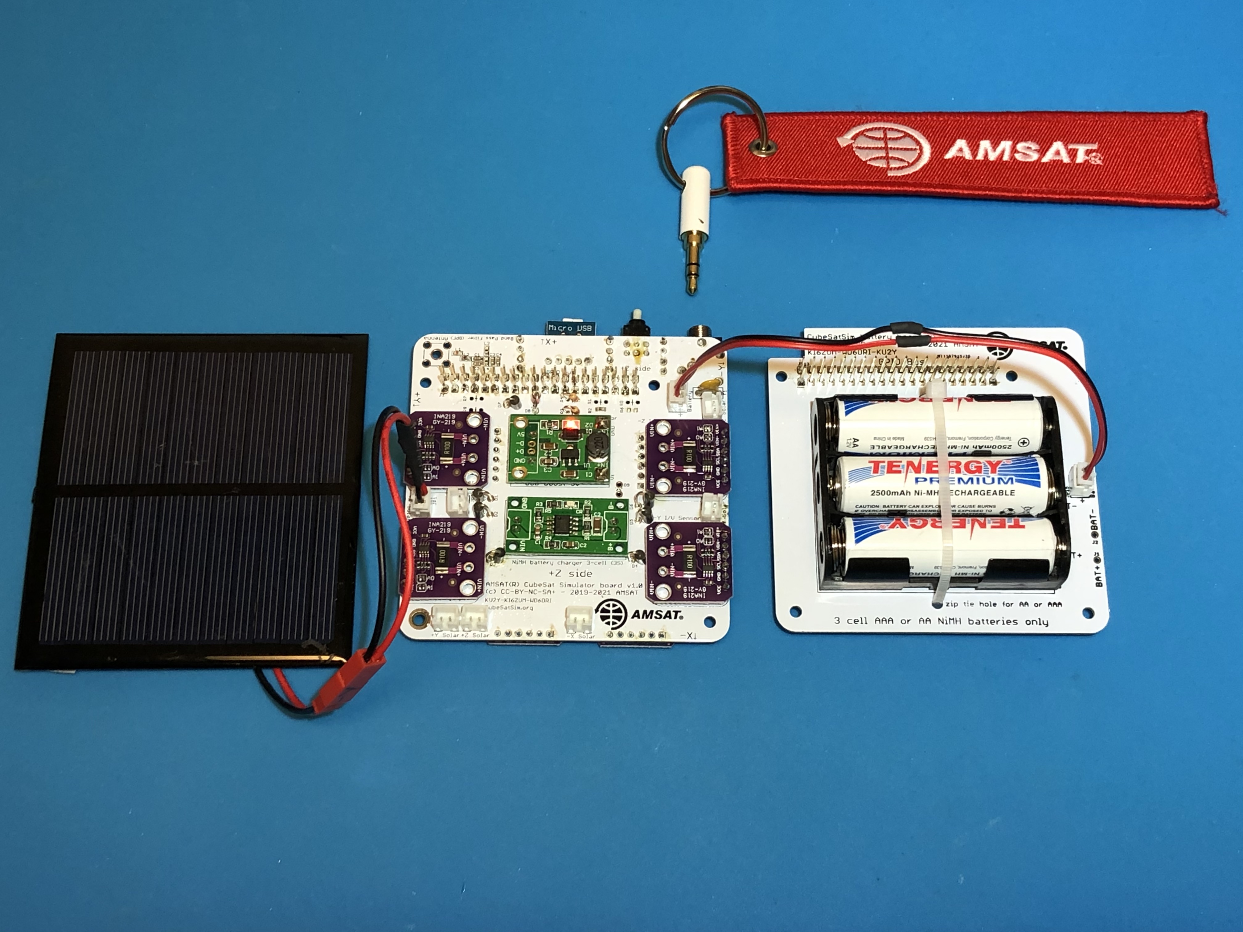
For the following tests, we use an arrangement known as a "Flat Sat" where the various CubeSat boards are connected side by side instead of stacked so you can get access to everything.
Making the RBF Pin
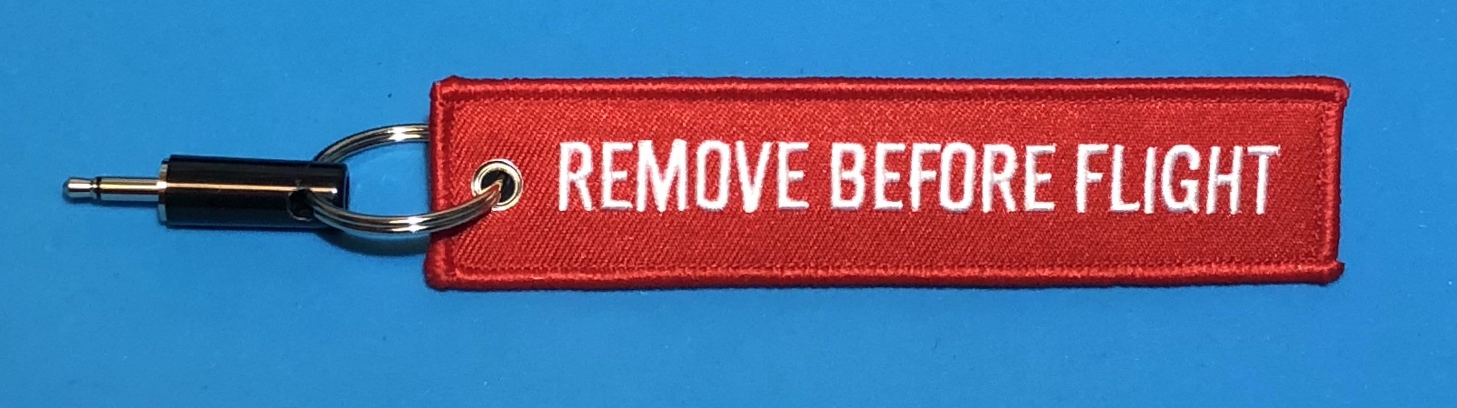
The Remove Before Flight (RBF) pin can be made out of any 3.5mm audio plug - it doesn't matter if it is mono, stereo, or TRRS, and nothing needs to be wired inside the plug. A 3D printed part in the shape of a 3.5mm plug also works! For that "ready to launch look", you can drill a hole through the cap and insert a Remove Before Flight keychain.
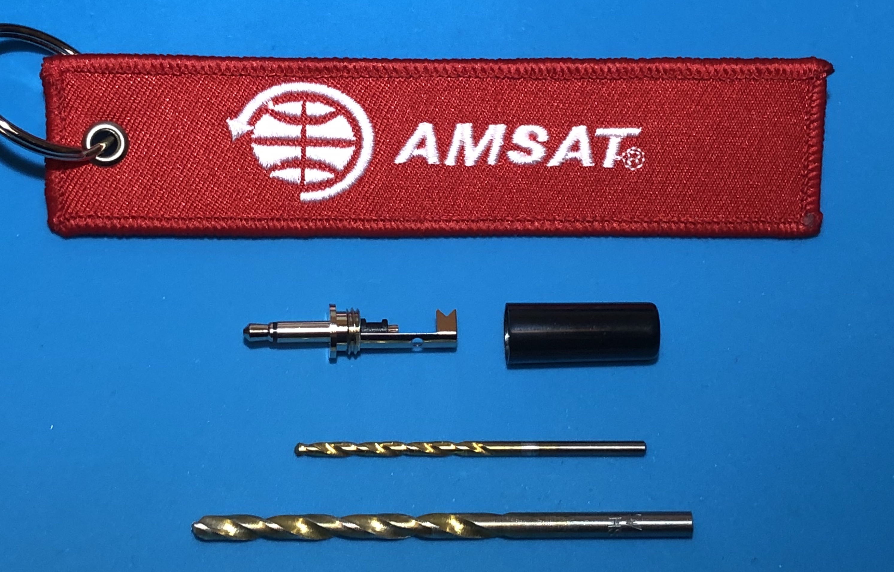
Drill a small hole first (3/32" bit) then a larger hole (5/32" bit) near the end of the cap.
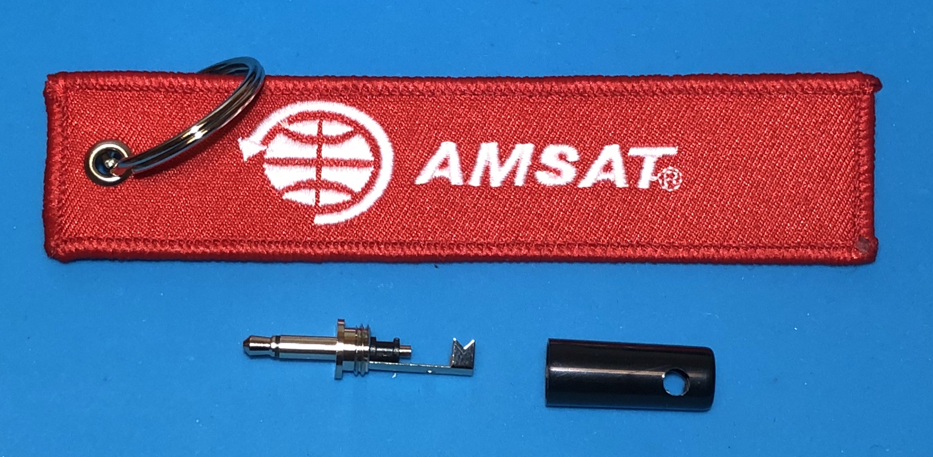
Then insert the RBF keychain through the hole. You will probably need to cut off part of the 3.5mm jack to make room.
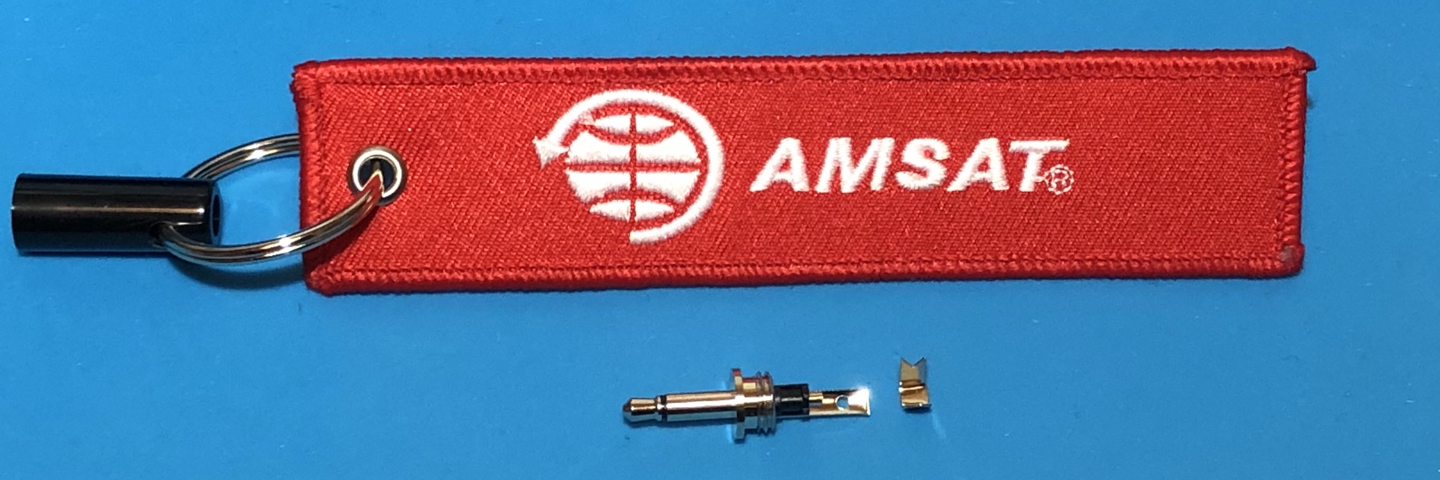
Screw the cap into the plug, and your RBF pin is ready to test
Final Testing
Here is a video of the final testing of this step: https://youtu.be/B05qusSro0g
RBF Switch Test
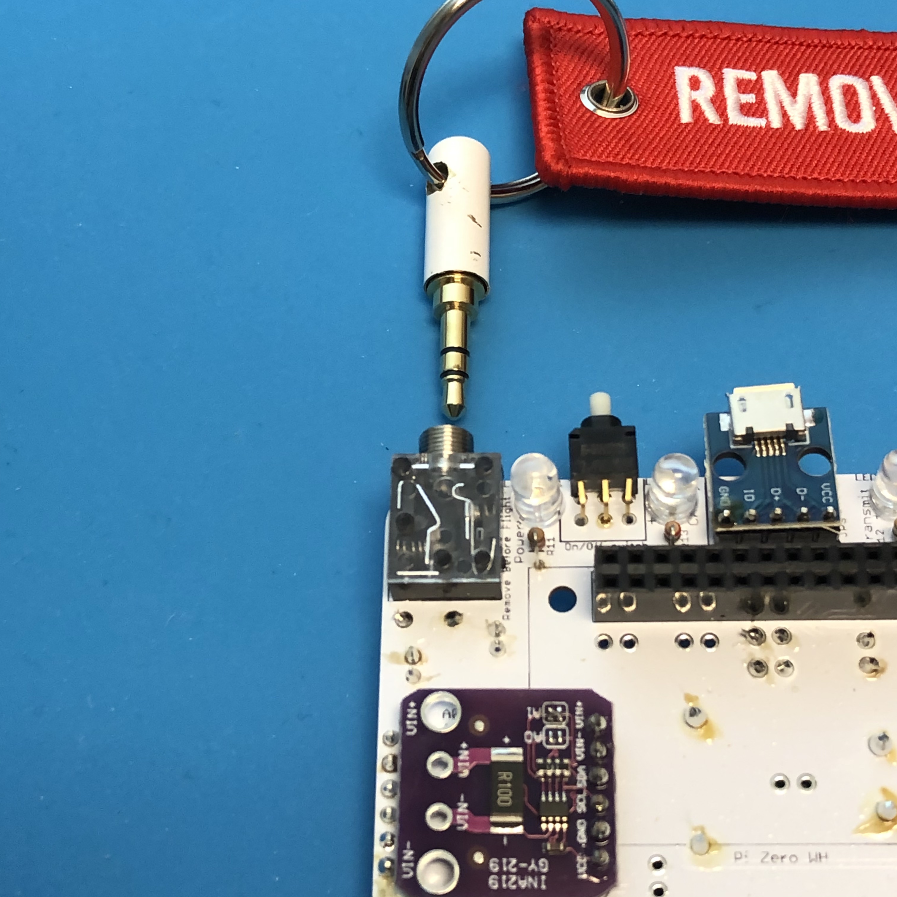
Inserting the RBF pin into the jack on the Main board disconnects the 5V power to the Raspberry Pi. If you look closely inside the clear cover of the switch, you can see two mechanical contacts which are closed (connected) with the RBF pin unplugged:
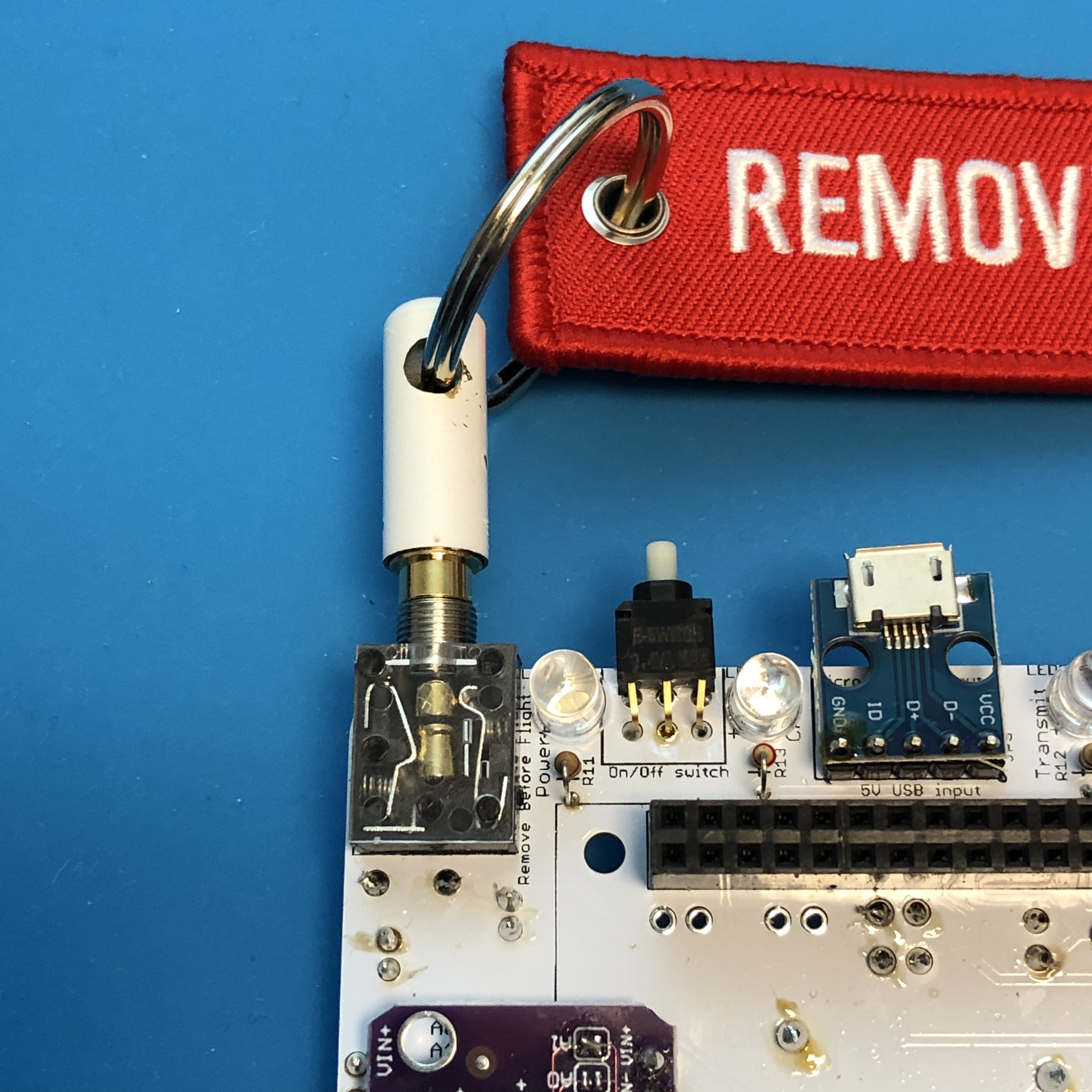
Insert the 3.5mm plug into the RBF switch all the way. You can see the two contacts are now opened:
From now on, every time you are plugging or unplugging boards or wires into the CubeSatSim or storing or shipping it, you should insert the RBF pin to ensure it stays powered down. But always shut down the Pi using the Push Button before inserting the RBF pin, or the SD card file system could become corrupted and require you to reflash the CubeSatSim image.
With the RBF pin safely inserted, plug the Pi Zero with the micro SD card with the CubeSatSim image installed into the bottom of the Main board. Plug the Battery board JST connector into the Main board. Plug in a solar Solar Panel.
Verify that there are no lights on the board. Verify that pressing the pushbutton does not start the CubeSatSim with the RBF pin inserted.
If the RBF pin inserted does not prevent the CubeSatSim from starting, make sure the 3.5mm plug is inserted all the way, or check the installation of the RBF switch.
Running on Battery Test
Now unplug the RBF pin and verify that the CubeSatSim starts up in about 30 seconds.
If removing the RBF pin does not start the CubeSatSim, make sure the battery is connected and not fully discharged. Make sure the Pi is plugged in and has a programmed micro SD card. Also, make sure the PTC F1 is soldered in correctly.
With the Battery connected and the RBF pin removed, the CubeSatSim will now run on a charged battery (battery voltage higher than 3.2 V). On a fully charged AA battery pack, it will run for about 3 hours. On a fully charged AAA battery pack, it will run for about an hour. If the battery pack voltage falls below 3.2 V, the CubeSatSim will automatically shut down. This doesn't hurt the CubeSatSim, and is an example of it switching to "safe mode" to protect the batteries from full discharge, just like a real spacecraft. If the CubeSatSim goes into safe mode and shuts down due to low battery voltage, you should then plug in the RBF pin and plug in the USB charging cable to the Main board. After a short while, you can remove the RBF pin and the CubeSatSim will restart. Keep the USB charging cable for a while to fully recharge the battery.
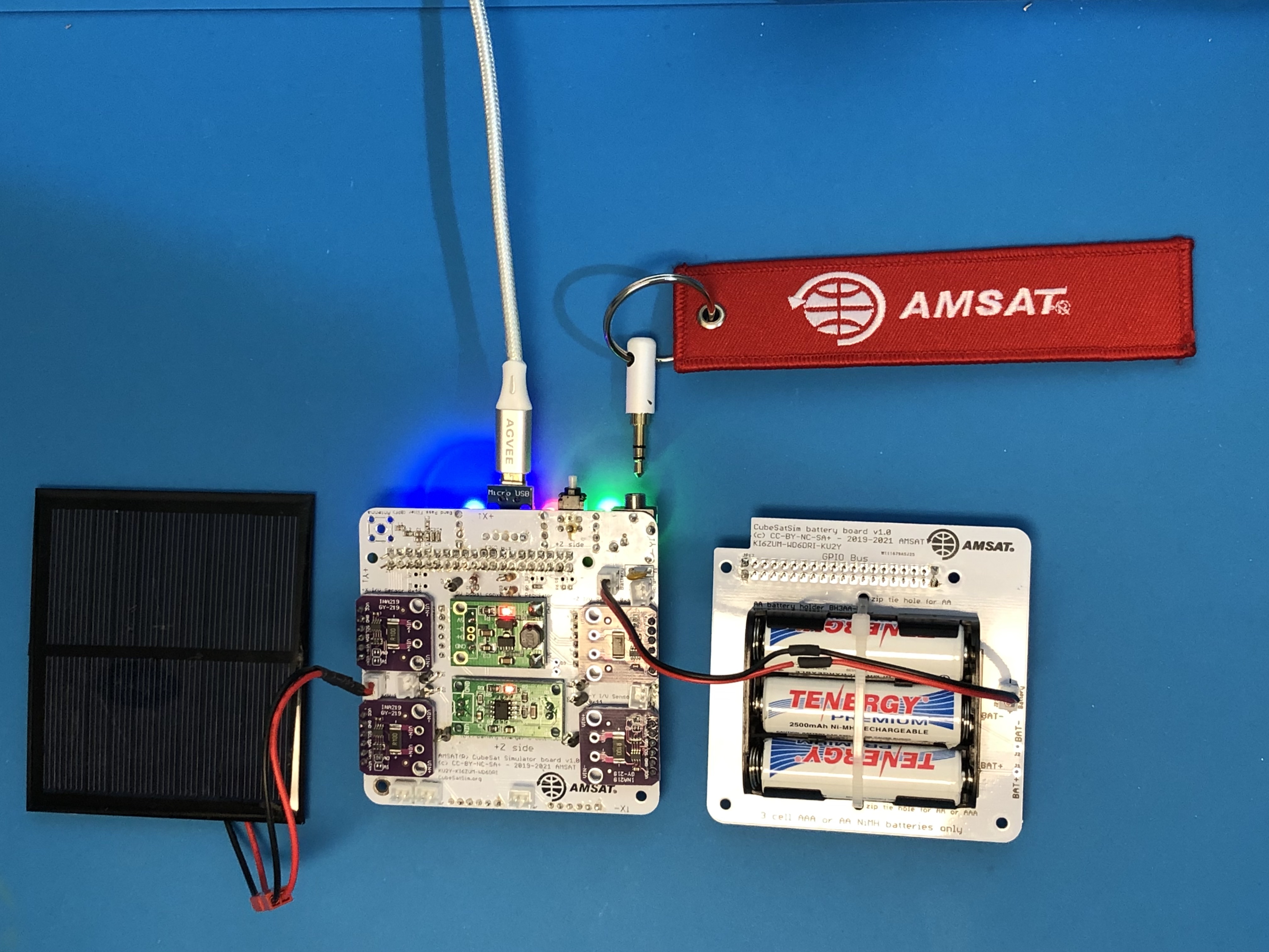
If the CubeSatSim is shut down, pressing and releasing the Push Button or removing the RBF pin will turn on the CubeSatSim. When running on battery, a single small red LED will illuminate on the 5V Regulator board, as shown here:
Charging Test
From now on, the USB charging cable should only be plugged into the Main board, not plugged directly into the Pi. When you plug in the USB charging cable to the Main board micro USB port, the red Charging LED will illuminate and a small red LED will illuminate on the Battery Charging Board as shown here:
In FoxTelem, the Battery Voltage will rise and the Battery current will be negative, indicating the current is flowing into the battery to charge it. If the battery is discharged, this could be around 300 mA, or less than 100 mA for a fully charged battery.
If you don’t get charging or the red charging LED doesn’t illuminate, there might be a problem with the Charging Board or your USB charging cable or power outlet.
Shut down the CubeSatSim by pressing and holding the Push Button until the green Power LED flashes slowly. After 30 seconds, plug in the RBF pin. The red Charge LED should stay on and also the small LED on the Battery Charging board. The 5V Boost Regulator LED should turn off, as shown here:
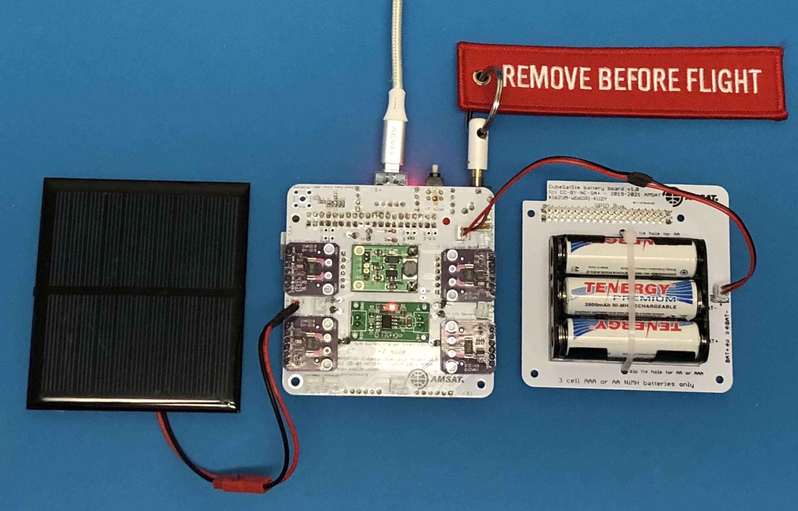
This means that you can charge your batteries even with the RBF pin inserted.
Solar Panel Current Sensor Test
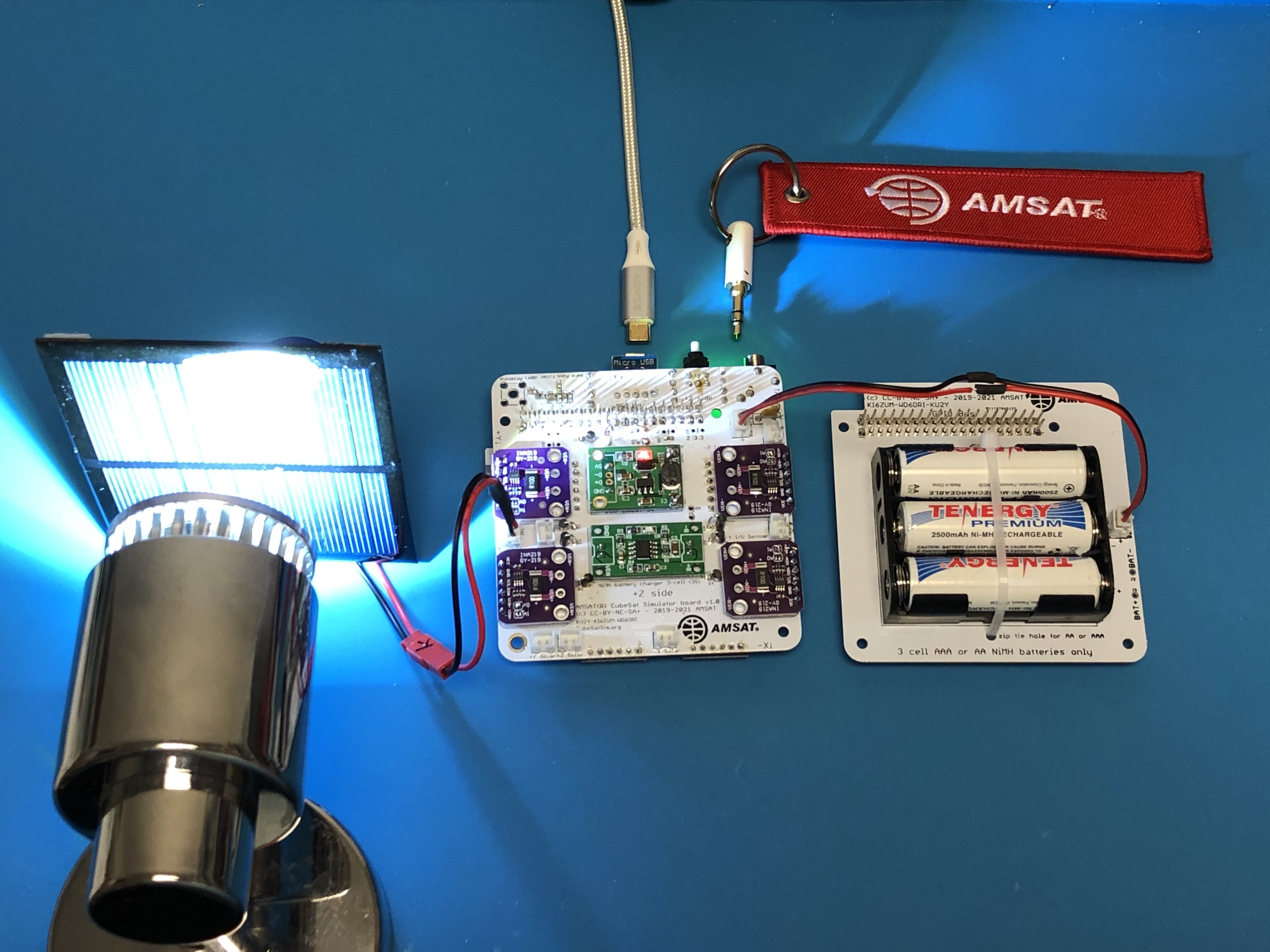
Weak illumination of a solar panel will generate a voltage you can measure, but no current will be generated. To generate a current, you need strong illumination. If you can position a desk lamp very close to the solar panel, you can measure a few milli Amps of current, as shown here:
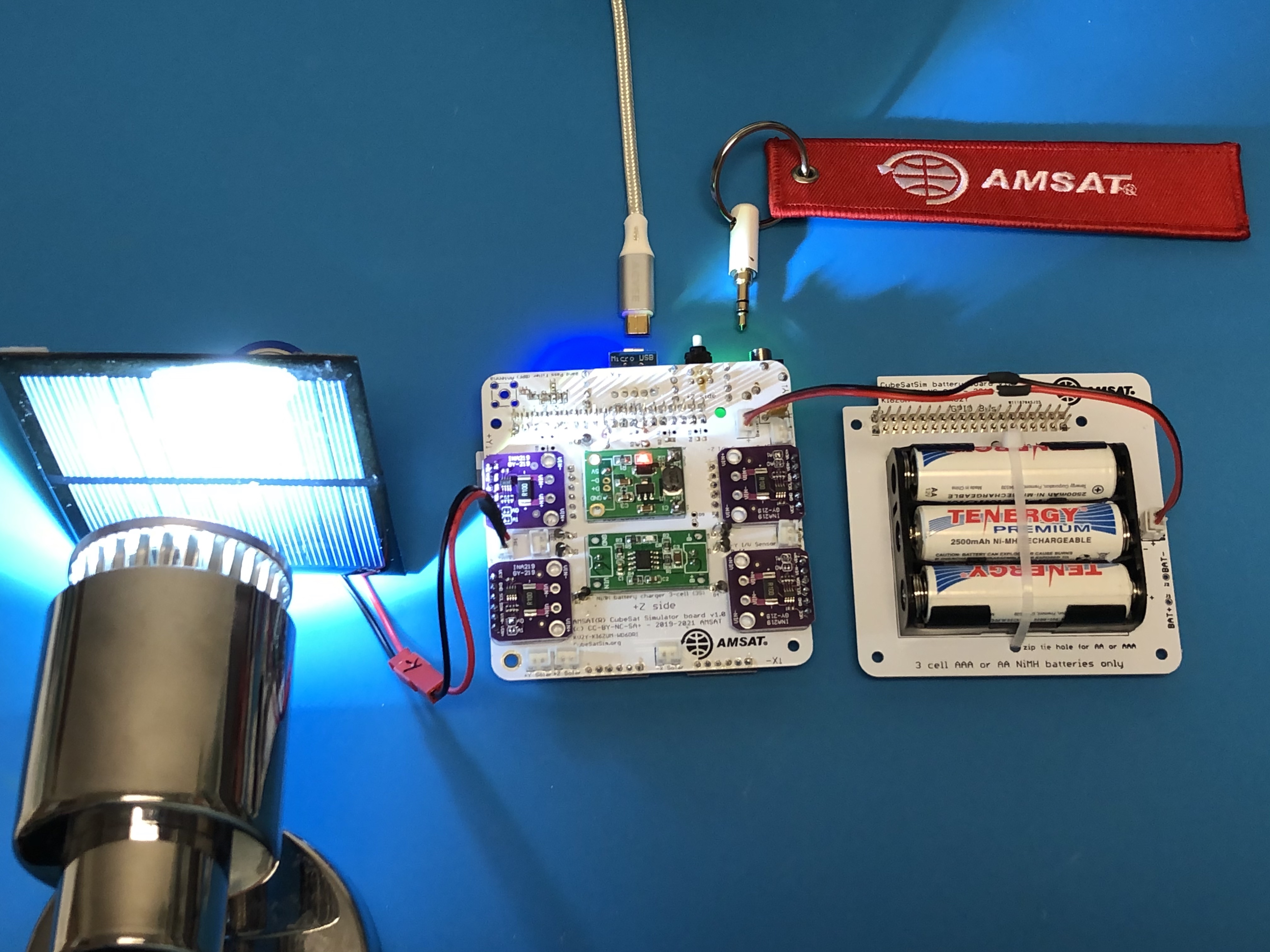
If you can position the solar panel in direct sunlight, you can measure around 100 mA of current.
In FoxTelem or using telem command line, you can verify that each Solar Panel (+X, -X, etc) generates current under sunlight or lamp illumination.
If no current flows, make sure the Solar Panel is getting good illumination from the sun or a lamp.
Results
If your CubeSatSim has passed all these tests, congratulations, the status of your CubeSatSim is “nominal” :-)
Note: For a spacecraft, “nominal” means fully functioning with no anomalies or problems.
The next step is to build the STEM Payload board.