V2 Stacking, Camera, and Frame - alanbjohnston/CubeSatSim GitHub Wiki
Stacking the Boards
The three boards in the board stack are shown here:

The stacking order is (from the bottom, left to right in the above image) Batt board, Pico board, Solar board. The ESP32-CAM plugs into the Pico board. The extra stacking headers are already plugged into the Batt board and the Pico board in this photo.
The standoffs to use are M2.5. screws are used on the top and on the bottom through the bottom frame.
This image shows the hardware with the left side at the top:

The standoffs at the bottom are 4 M2.5 15mm.
The standoffs between each the three boards are made up M2.5 20mm+6mm and M2.5 6mm+6mm. There are 8 of these.
Start stacking with the Batt board. The 15mm standoffs go underneath the board, and the four 20mm+6mm, nut, and 6mm+6mm stacks goes on the top. The resulting stack looks like this:

From the side, it looks like this:

Next, plug the Pico board on top, making sure there is a stacking header in between the boards. Make sure the RBF plug is inserted, otherwise the CubeSatSim will power up.

Plug the ESP32-CAM board into the side of the Pico board:

Screw the four 20mm+6mm, nut, and 6mm+6mm stack into the board:

Next, plug the Solar board on top, meowing sure there is a stacking header in between:

Secure the Solar board with four screws:

The four remaining screws are to secure the stack to the bottom of the frame.
The resulting stack looks like this:

The stack is now ready to be installed in the Frame
Camera
The instructions for the ESP32-CAM are here: ESP32 CAM for Pico
Solar Panels
Any solar panel that is 5V - 6V and less than 90mm in length will work. For side with the camera and the side with the pushbutton, USB-C charging port, and the LEDs, the longest dimension of the solar panel is 45mm.
The recommended solar panels are 72mm x 45mm, and there are two mounted on each side, except the top and bottom that have just one. (You can also mount two solar panels on the top and bottom, although the solar panels are commonly sold in batches of 10.
The 10 solar panels need to have the JST 2.0 connectors soldered on:

Some liquid flux can be applied to each pad of the solar panels to make soldering easier. Also, hot glue can be used to stick the insulation of the wires to the panel to provide extra strength.

Here's how the panels look after the protective film is removed:

Frame
Here are the v2 Frame STL files: https://github.com/alanbjohnston/CubeSatSim/tree/pico/hardware/framev2
You need to print two of each. Here's the frame parts with the ten Solar panels, plastic screws and nuts, and velcro to secure the panels to the frame:

The 1U frame of the CubeSatSim has solar panels on each face, which are labeled by the Cartesian axes X, Y, and Z. For the sides that face in the direction of the axes (see https://en.wikipedia.org/wiki/Cartesian_coordinate_system#/media/File:Coord_system_CA_0.svg), they are labeled +X, +Y, and +Z. For the sides that face in the opposite direction, they are labeled -X, -Y, and -Z. The CubeSat Design Specification (CDS) standard also has drawings showing the X, Y, and Z sides of a 1U CubeSat https://www.cubesat.org/cds-announcement. Here is a figure from that document:
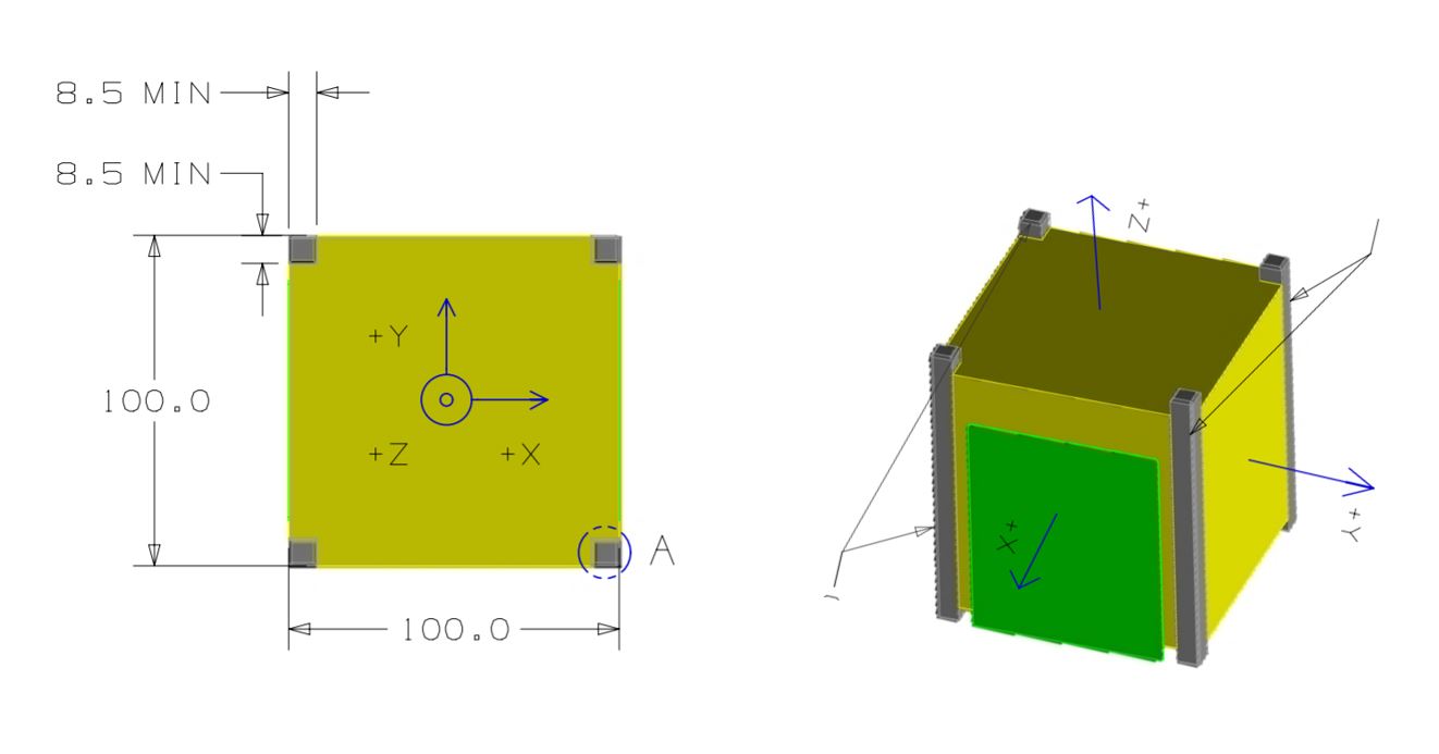
On the CubeSatSim, the +Z side is the top of the CubeSatSim, the +X side has the pushbutton, micro USB connector, and the LEDs. The Main printed circuit board has the axes labeled on it as well.
Start with the top and bottom of the frame (the +Z and -Z sides). One solar panel is mounted on each. Two strips of velcro or double stick tape are used to secure them, aligned with the ribs on the frame:

Here's how they look when mounted:

Now get ready to attach the two sides to the frame bottom using the four plastic screws. Just start the screws - do not tighten them:

Attach the two sides to the frame bottom:

The sides of the frame with supports that go all the way across are the +X and -X sides:

The sides of the frame with supports that are in a "D" shape, are the +Y and -Y sides:

Now get ready to mount the solar panels on the +X, -X, +Y, and -Y sides:

Start with the +Y side. Attach the velcro or double stick tape to corners of the "D":

Slide the frame top in place so the sides are spaced correctly, but do not secure it. Attach the solar panel. The bottom of the solar panel should go slightly beyond the bottom frame:

Do the same to the top panel:

Now do the +X side:

Attach the velcro or double stick tape to the horizontal frame parts:

Then attach the solar panels:

Do the same thing for the -Y and -X sides. Here's how it looks with all the solar panels attached:


Now remove the frame top and the top solar panels on the +Y and -Y side. Carefully move all the solar panel wires to the side. Identify and route the -Z solar panel wire (the one on the bottom) as shown. Orient the board stack with the frame as shown here (note the location of the round hole in the frame bottom):

Carefully place the board stack inside the frame. You will have to spread the sides slightly which will be possible since the screws to the bottom are loose:

When the board stack is in place, remount the -Y and +Y top solar panels. Plug in the -Z, +X, -X, +Y, and -Y solar panel connectors as shown:

Secure the board stack to the frame bottom first with one screw:

Then secure it with the other 3 screws:

Plug the +Z solar panel connector on the top frame into the board. If the SMA antenna is in use, connect the SMA coax to the frame:

Carefully lower the top frame into place. The SMA coax will need to be bent. This photo with a solar panel removed shows the coax:

Secure the frame top with 4 plastic screws. You will need to remove the top -Y and +Y solar panels to do this.

Mount the SMA antenna:

Here's how it looks:


Here is the completed CubeSatSim:
