V2 Sensors - alanbjohnston/CubeSatSim GitHub Wiki
Sensors for CubeSatSim V2
These instructions are for soldering and testing the Sensors.
Here are the parts you need:
- Raspberry Pi Pico or Pico W
- Micro USB Cable for programming Pico
- BME280 sensor and 1x4 male pin header
- MPU6050 sensor and 1x8 male pin header
- Two 4.7k resistors (purple yellow red bands)
- Solderless breadboard
- Jumper wires (male to male and male to female)
- Soldering iron, solder
Soldering the Sensors
The purple BME280 sensor and MPU6050 sensors need to have pin headers soldered onto them before they can be tested.
Make sure you solder the pin headers on the right side and the right way.
On the BME280, the side of the board with the sensor IC (the tiny metal can) should be up. On the MPU6050, the side with all the components should be up.
Solder one pin then check to make sure the pin header is at right angles to the board. If not, reheat the pin and straighten. Finish soldering the rest of the pins.

The sensors are now ready to test.
Testing the Sensors
We are going to test the sensors with the programmed Raspberry Pi Pico Board. If it is programmed, when you power it up, after about twenty seconds, the green LED on the Pico should flash a Morse Code message. If your Pico hasn't been programmed yet, follow theses instructions first V2 Pico Software.
Instead of plugging the Raspberry Pi Pico microcontroller into the breadboard, we are going to flip the Pico upside down and connect six pins to the breadboard using female to male jumper wires. The bottom of the Pico has labels on each of the pins.
Here is a map of the Pico pins as viewed from the top: https://pico.pinout.xyz
Start by connecting six pins on the Pico to the solder less bread board. Use the male to female pins which will plug into the bottom of the Pico:
- Connect the pico pin GP4 (pin 6) to the BME pin SDA
- Connect the pico pin GP5 (pin 7) to the BME pin SCL
- Connect the pico pin 3V3 (pin 36) to the BME pin VIN
- Connect the pico pin GND (pin 38) to the GME pin GND
- Connect a 4.7k resistor between the BME pin SDA and the BME pin VIN
- Connect a 4.7k resistor between the BME pin SCL and the BME pin VIN
Here is how this should look.
There are five columns of holes. If you plug the BME280 into the first column, plug the four wires into the 2nd column, leave the 3rd column empty, then use the 4th and 5th columns for the 4.7k resistors.
Plug the Pico USB cable to your computer. Close the Serial Monitor in the Arduino IDE then reopen it. Here is what you should see:
Reading mode

CubeSatSim Pico v0.40 starting...

Pico W detected!
Pi 3.3V: 1
Pi Zero present, so running Payload OK code instead of CubeSatSim code.Starting payload!
Could not find a valid MPU6050 sensor, check wiring!

OK BME280 26.20 1009.15 34.17 16.58 MPU6050 -0.0 0.1 0.0 -0.0 -0.0 0.0 GPS 0.0 0.0 0.0 TMP 0.0
The OK is the status response. The four numbers after the BME280 are the temperature in Celsius, pressure in hPa, altitude in meters, and humidity in percentage read from the purple BME280 sensor.
If you still get four zeros after the BME280, then there is a problem with the sensor. Go to the Sensor Troubleshooting section later in this page.
Unplug the Pico USB cable to your computer.
Now wire up the MPU6050 sensor by wiring, using male to male jumper wires:
- A jump wire from VCC on the MPU6050 to VIN on the BME280
- A jump wire from GND on the MPU6050 to GND on the BME280
- A jump wire from SCL on the MPU6050 to SCL on the BME280
- A jump wire from SDA on the MPU6050 to SDA on the BME280
Here's how it should look:
Plug the Pico USB cable to your computer. Close the Serial Monitor in the Arduino IDE then reopen it. You should see:
Reading mode`

CubeSatSim Pico v0.40 starting...`


Pico W detected!
Pi 3.3V: 1
Pi Zero present, so running Payload OK code instead of CubeSatSim code.Starting payload!
Calculating gyro offsets and storing in EEPROM

========================================
calculate gyro offsets

DO NOT MOVE A MPU6050...

Done!!!

X : -3.38
Y : 1.47
Z : 3.07

Program will start after 3 seconds
========================================ERROR! EEPROM commit failed

A07
0.00
0.00
0.00

OK BME280 26.82 1009.22 33.60 17.22 MPU6050 0.00 -0.13 0.15 -0.11 0.05 1.57 GPS 0.0 0.0 0.0 TMP -0.14
The six numbers after the MPU6050 are the X, Y, and Z axis angular rotation in degrees per second and the X, Y, and Z axis acceleration in g.
If you get all zeros for the MPU sensor, you need to determine if it is a hardware or software problem. See the section on Sensor Troubleshooting at the end.
You can verify the BME data changes by breathing on the purple BME280 sensor then looking at the output. If you uncheck the Autoscroll box in Serial Monitor, the data won't scroll off screen. You should see an increase in temperature and humidity.
You can verify the MPU data changes by tilting the solder less breadboard on its side then looking at the output. You should see the acceleration data change.
Installation in the STEM Payload Board
Once the sensors are soldered and tested, you are ready to plug them into the STEM Payload board in the TBD step.
Make sure the STEM Payload board is powered down. The MPU sensor goes in the upper right side of the Pico board, while the BME sensor goes in the lower side.
Once you plug in the sensors, power up the Pico board. Connect the Pico micro USB to your computer and run the Arduino Serial Monitor.
You should see the same OK and payload data.
If a Ground Station is available, you can verify the sensor data in packets received in FoxTelem.
The Sensors are now ready to be installed in the Pico Board and tested in the next step TBD
Sensor Troubleshooting
If you get all zeros for a sensor, you need to determine if it is a hardware or software problem. Running an I2C bus scanner program will tell you if the sensor can be accessed on the I2C bus. The program is:
https://github.com/alanbjohnston/CubeSatSim/tree/master/stempayload/i2c_scanner
Download this code, open it in the Arduino IDE, then upload this to your Pico and then open the Serial Monitor. You should see:
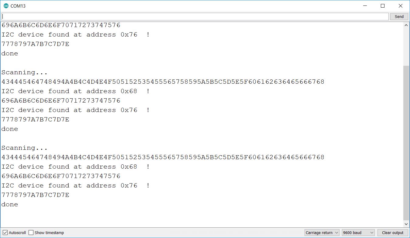
The blue MPU6050 should be at address 0x68 while the purple BME280 should be at address 0x76. If neither device is present on the I2C bus, make sure resistors are plugged in correctly and 4.7k Ohms in value. If one sensor shows up but not the other, it might be due to soldering on the sensor pins or due to a bad sensor board.
If the sensor shows up on the I2C bus but you get zeros in the Serial Monitor, this indicates a software problem.