V2 Camera - alanbjohnston/CubeSatSim GitHub Wiki
Step 7c: Pi Camera for Raspberry Pi Zero
In this step, you will assemble and test the Pi Camera with the Pi Zero.
Pi Camera Instructions
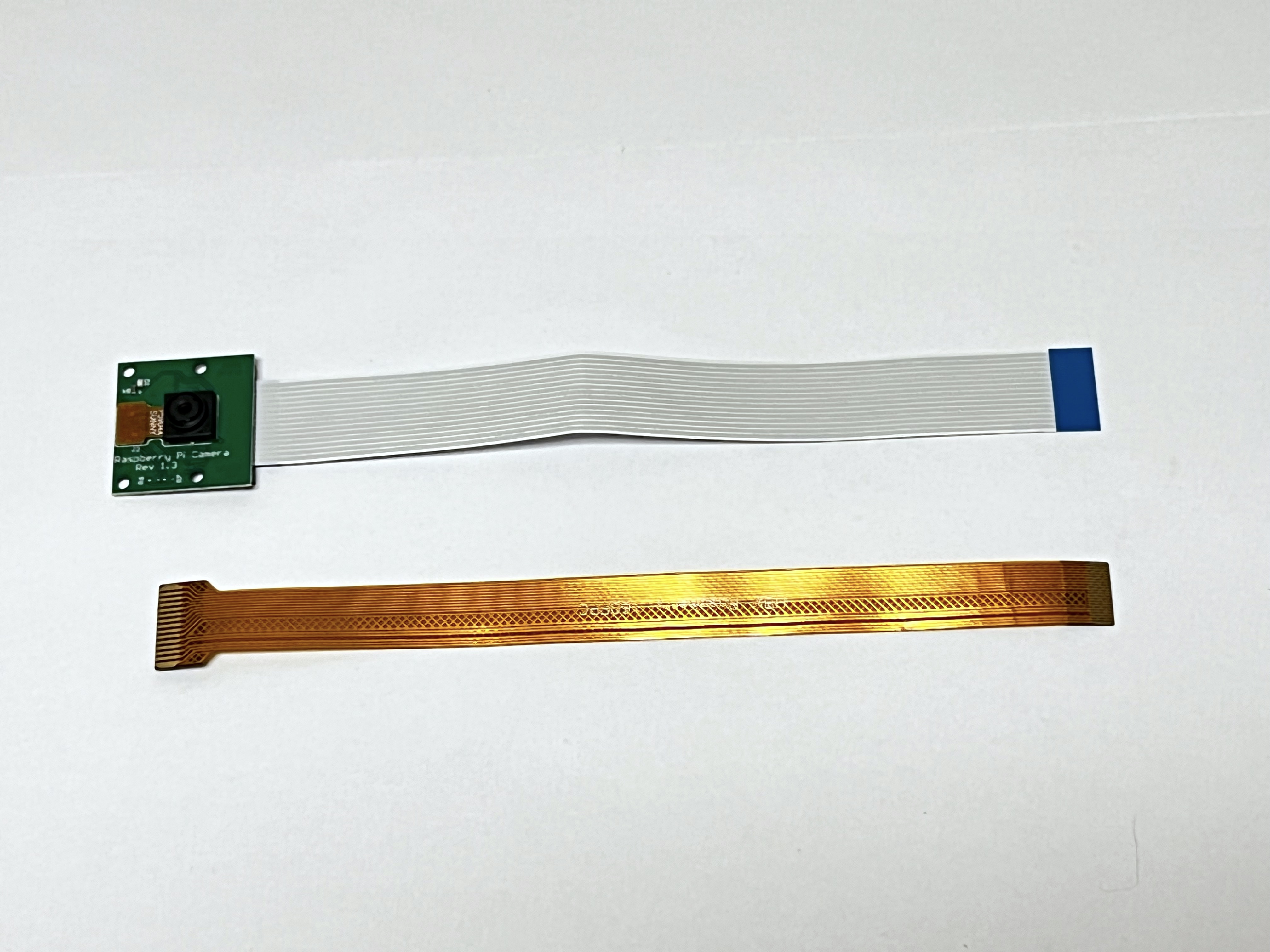
Here are the parts you need for the Pi Camera:
- Pi Camera
- 6.3 inch (16 mm) Camera cable for the Pi Zero W
- Pi Zero W with programmed micro SD card and micro USB power cable
- Computer to log into the Pi Zero and test the camera
Video
Here is a video on the Raspberry Pi Camera Installation (only the first 8 minutes are relevant): https://youtu.be/5ras2Y0Cfec
Most Pi Cameras come with the cable to connect to a full sized Pi, so you may need to buy a Pi Zero W Camera Cable as well:
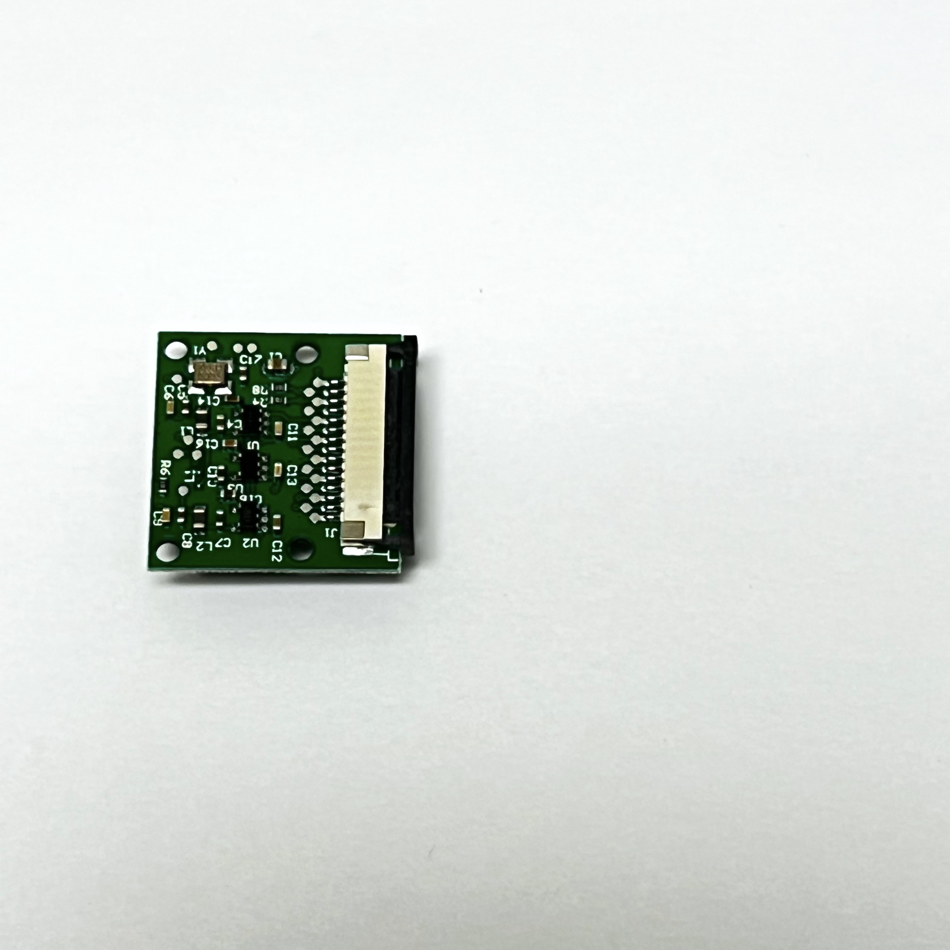
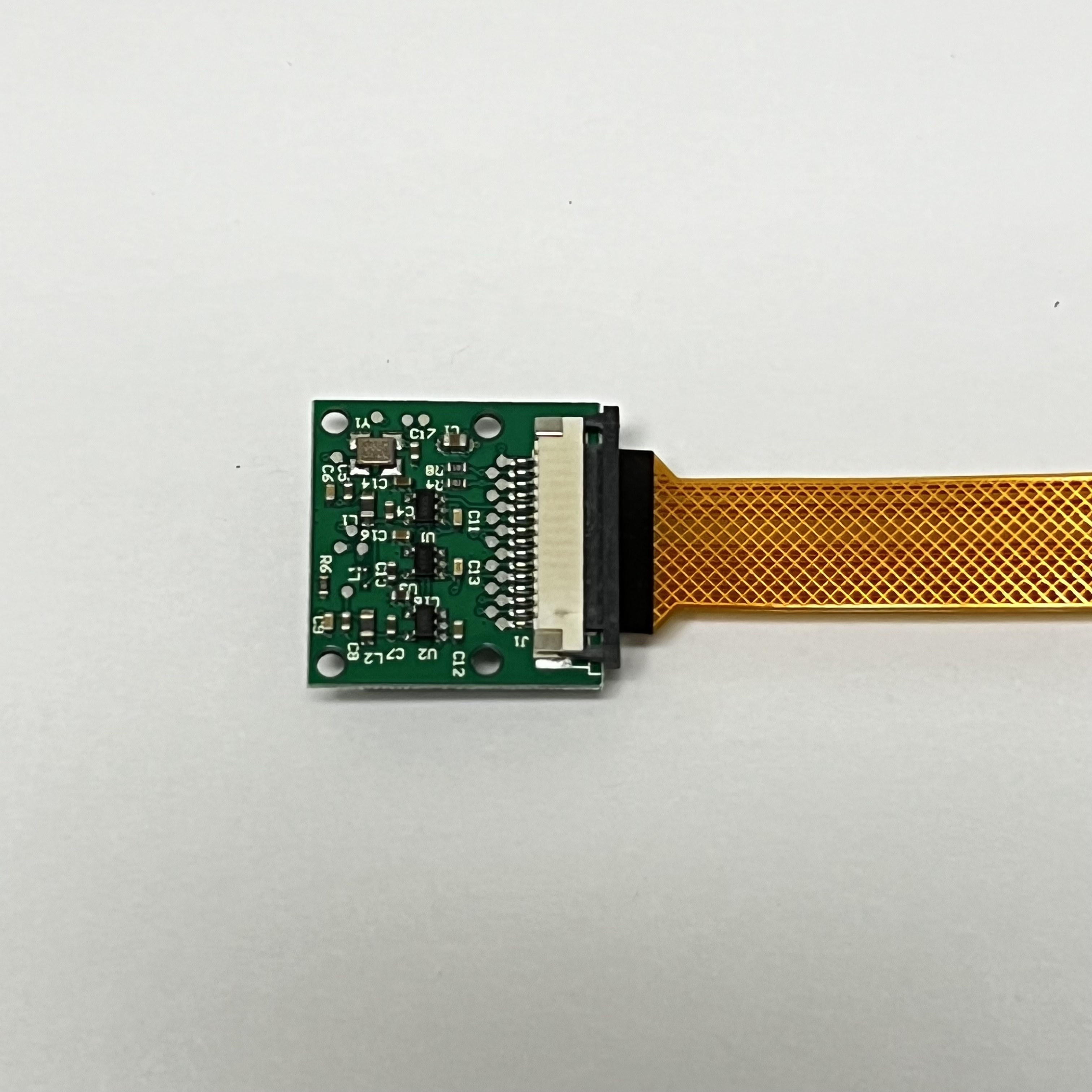
To disconnect the Pi Camera Cable, identify the slide lock on the connector on the back of the Pi Camera. In this photo it is the black plastic piece:
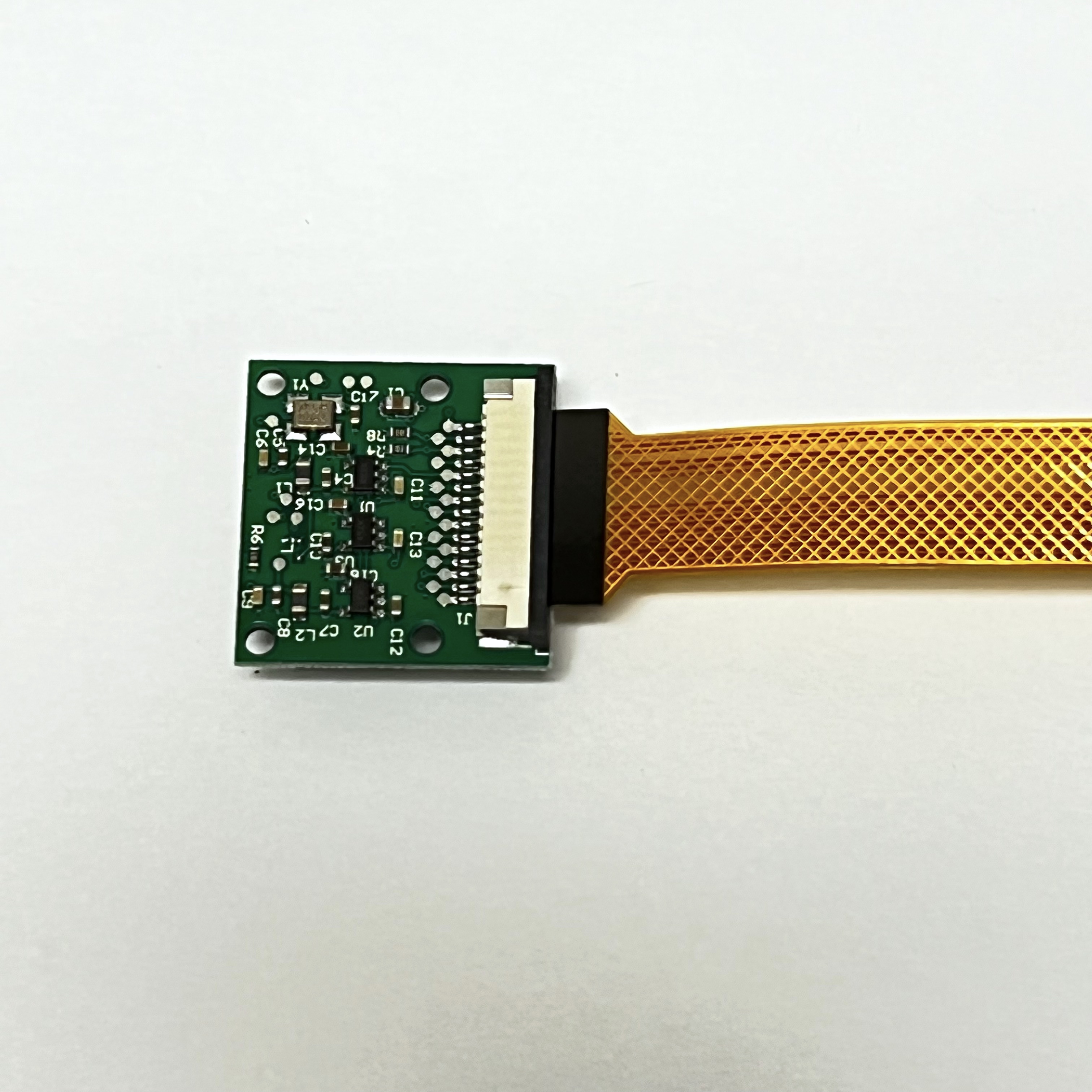
Carefully move the slide lock away from the board, to the right in this photo. You might need to move it a little on one side, then the other side. It only moves out a few millimeters and does not come completely off:
The cable will now be loose and you can slide it out and remove it.
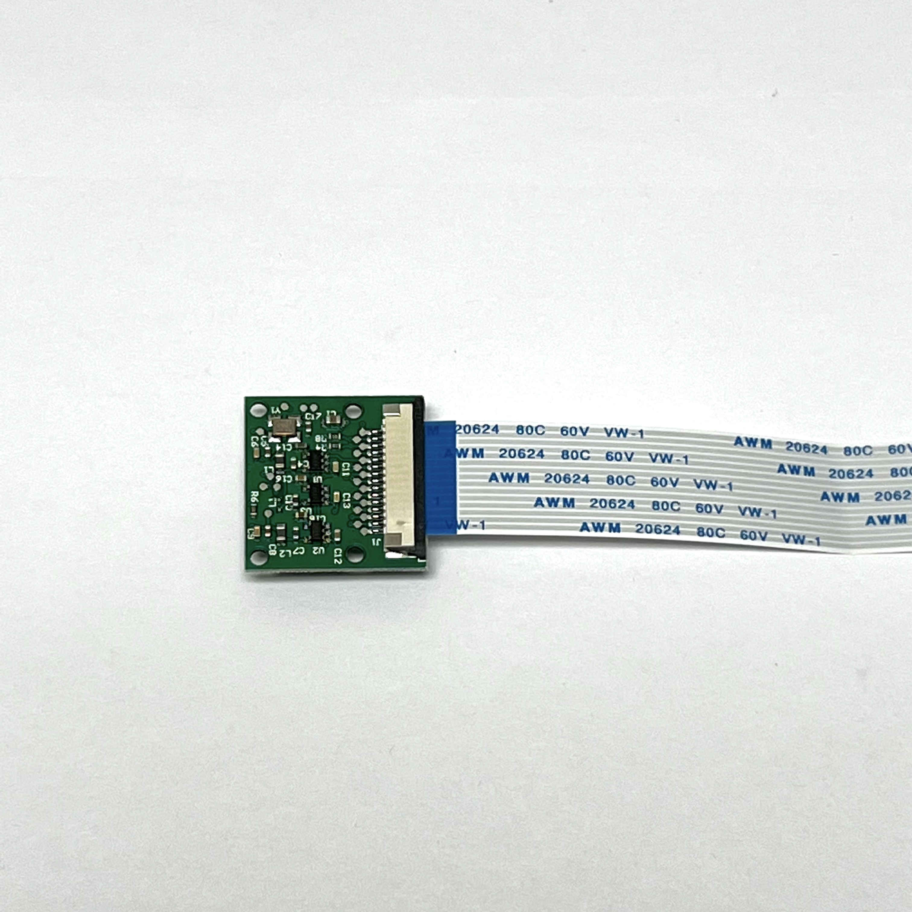
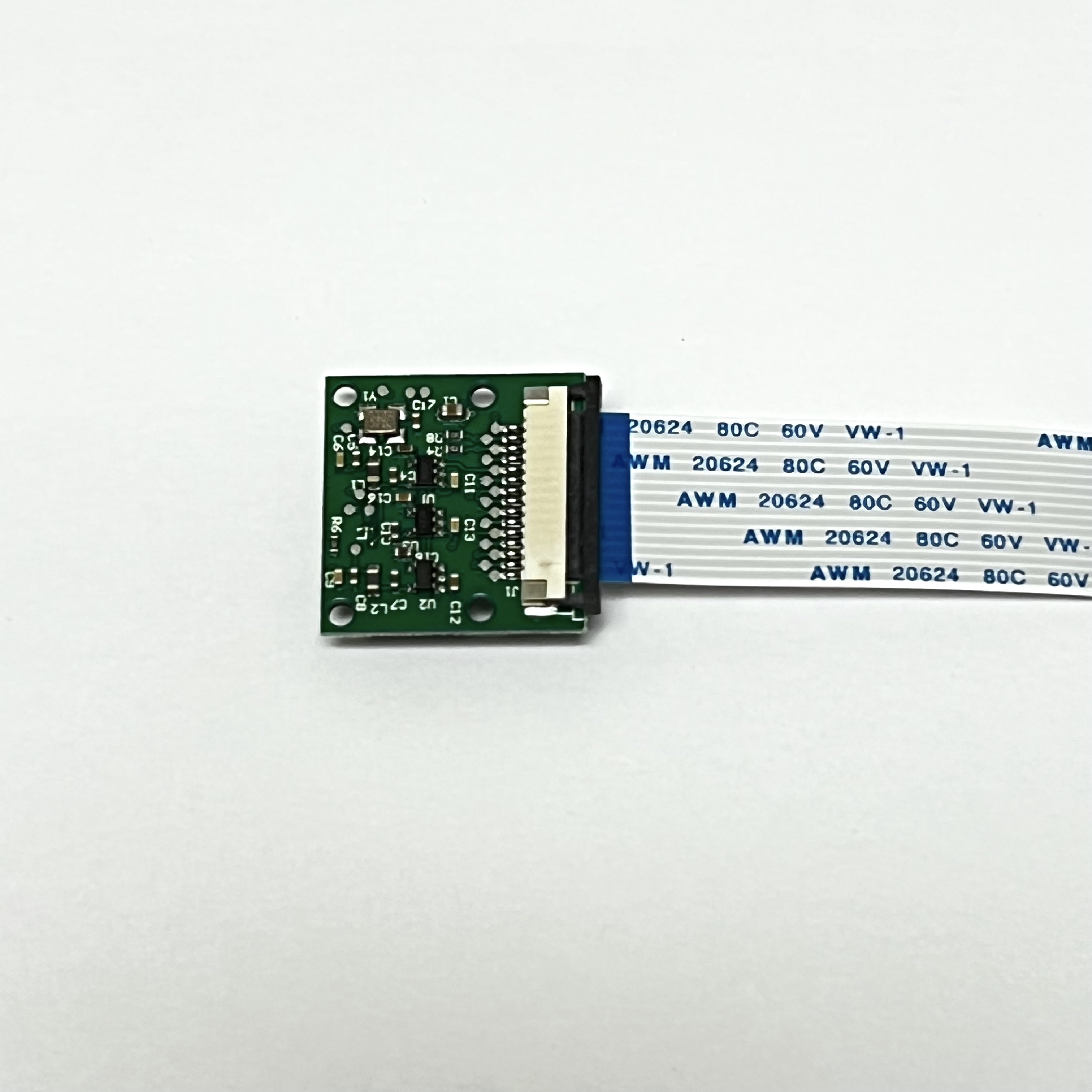
Slide the 6.3 inch (16 mm) Pi Zero Camera Cable into the connector. Make sure the metal contacts on the cable are facing the PCB, in this photo the contacts face down:
Carefully move the slide lock towards the board (to the right in this photo) to hold the cable securely. Make sure the cable doesn't slide over or get crooked:
This is how it looks on the other side.
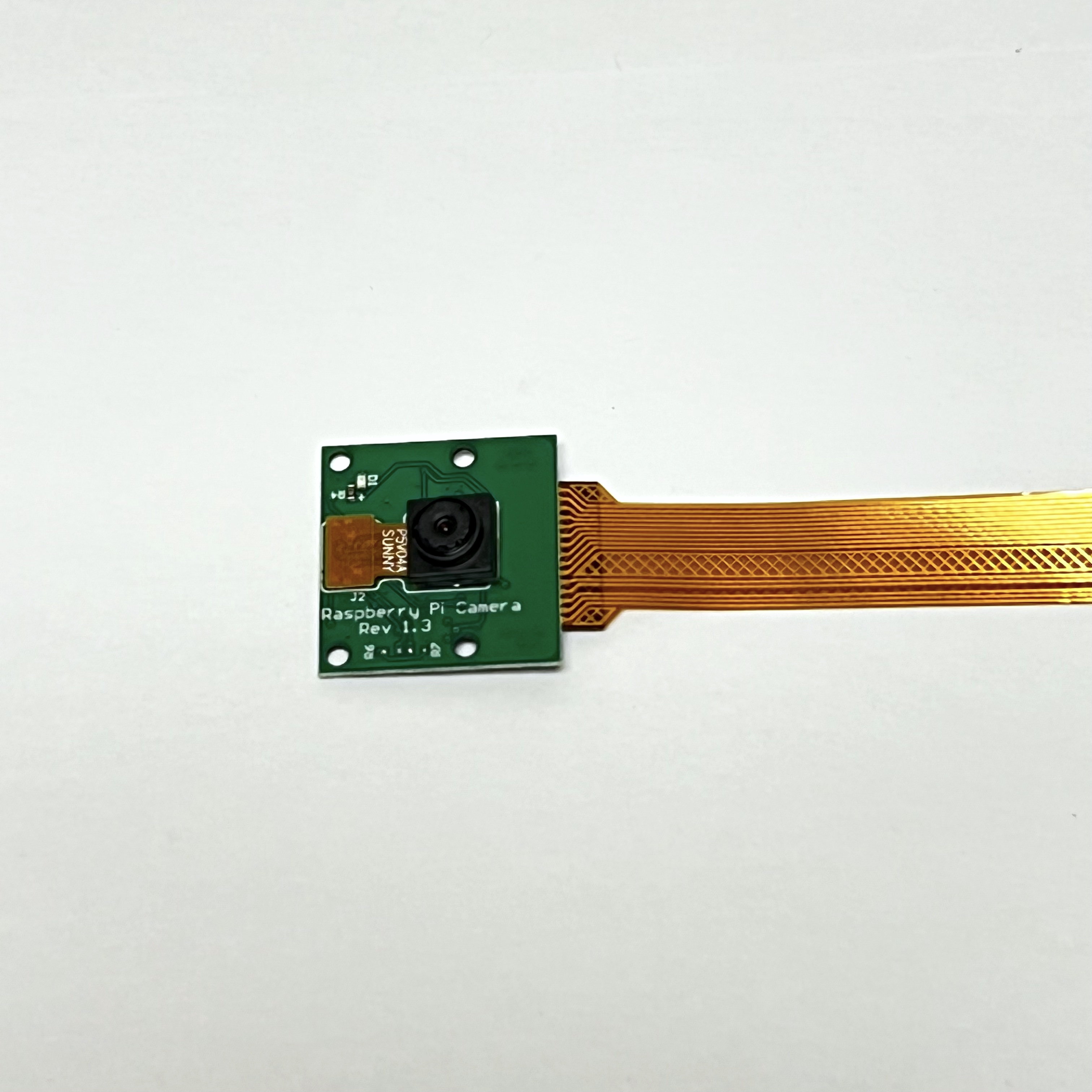
Don't forget to remove the plastic film over the camera lens!
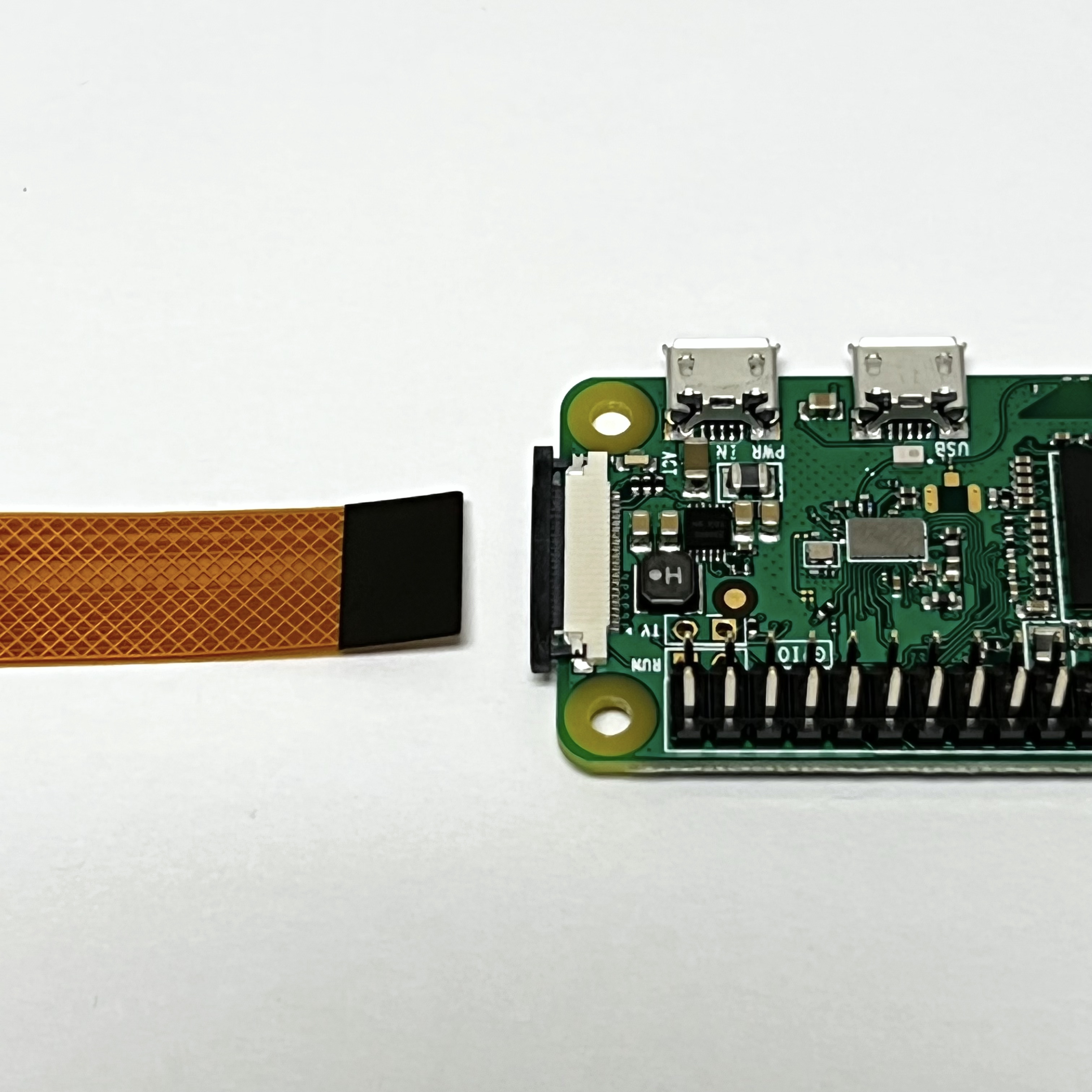
The camera cable plugs into the Pi Zero on the opposite side to the micro SD card. This is how the Pi Zero Camera Cable and the Pi look when ready to connect:
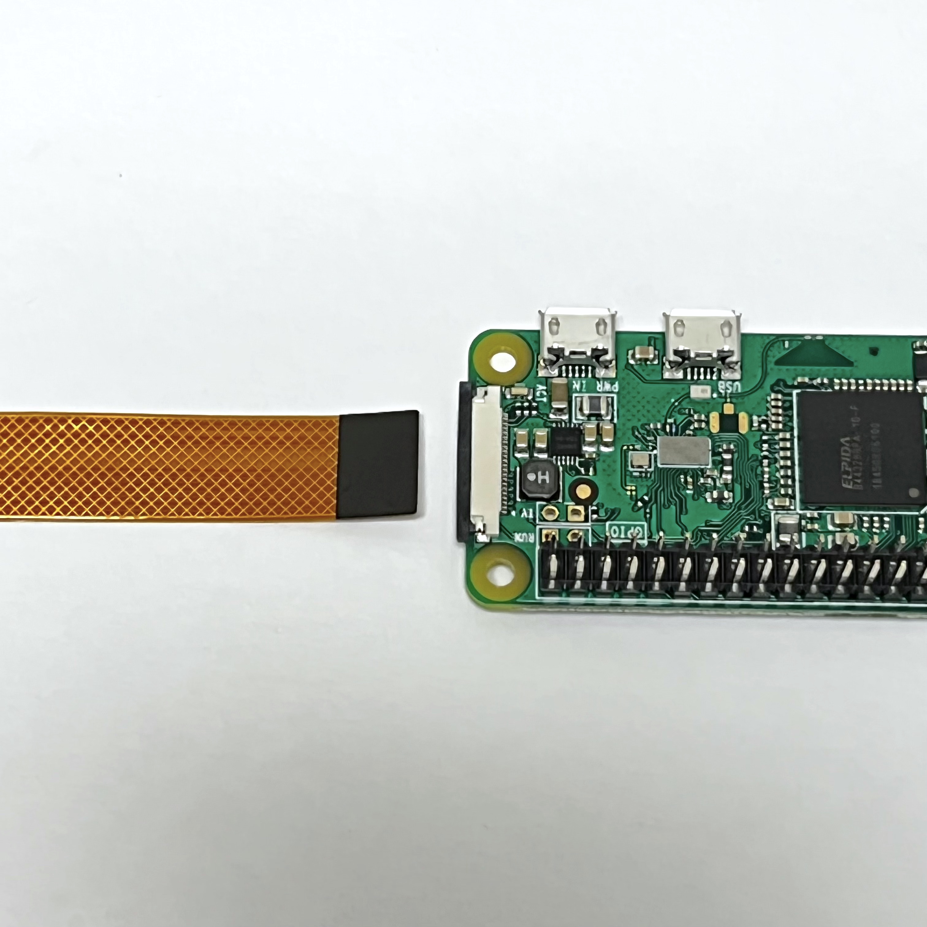
The other end of the Pi Zero Camera Cable connects to the Pi Zero WH on the opposite side to the micro SD card slot. Identify the slide lock, in this photo it is the black plastic:
Carefully move the slide lock away from the board, in this photo to the left. Be very very careful - it is very easy to break it. You might need to move it a little on one side, then the other side. It only moves out a few millimeters and does not come completely off. There may be a plastic "blank" in the slot - you can remove it.
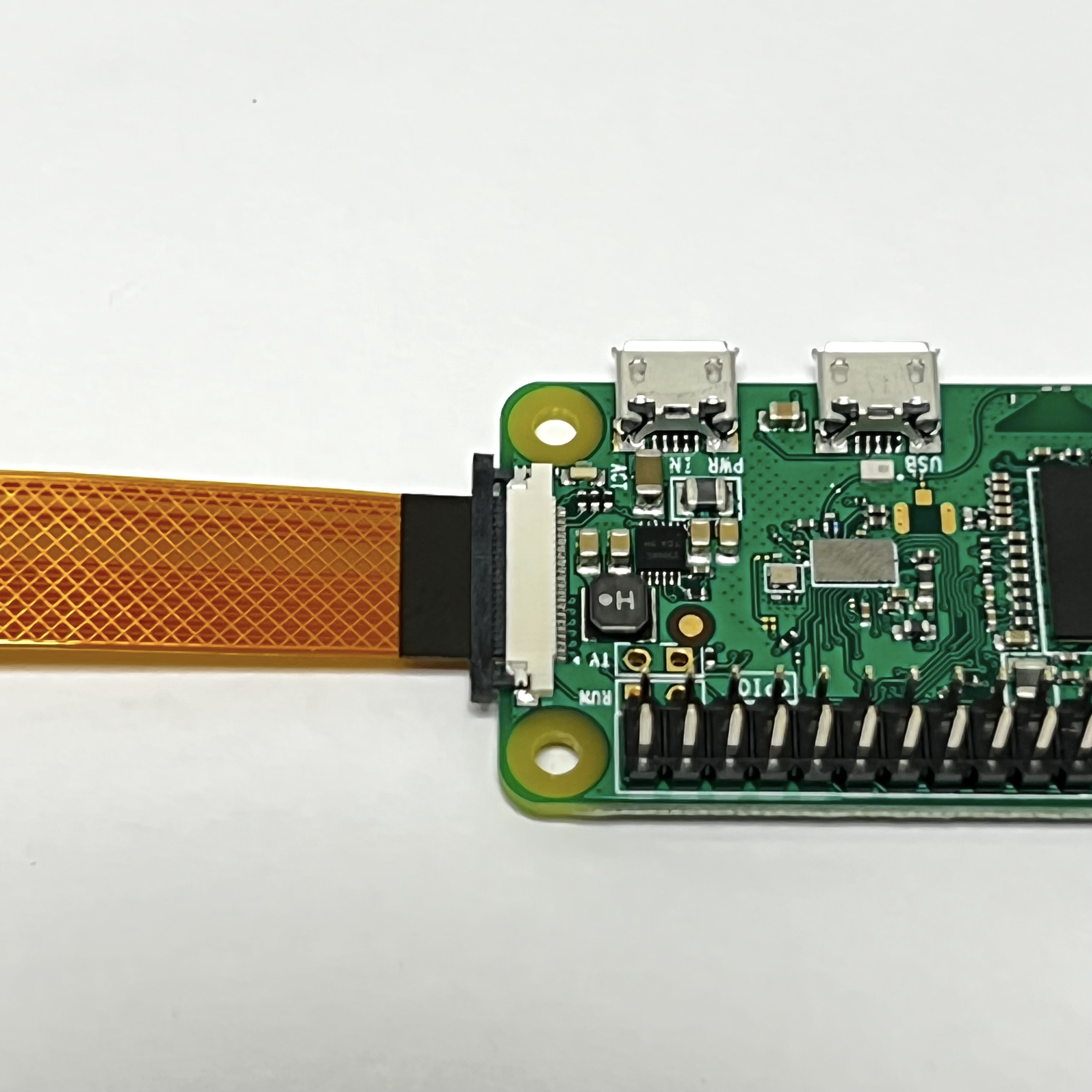
Insert the Pi Zero Camera Cable into the connector. Make sure the metal contacts are facing the PCB, in this photo facing down:
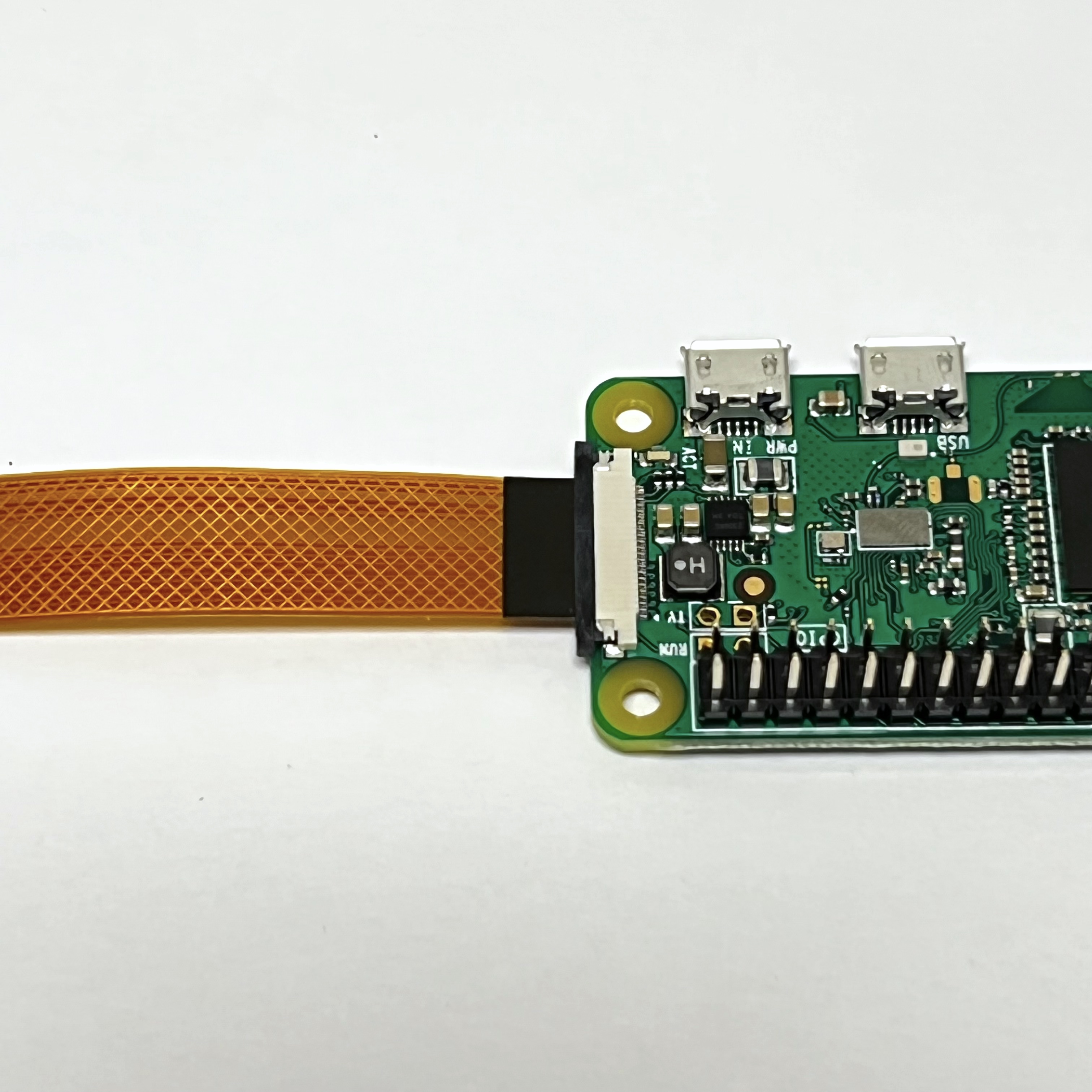
Carefully move the slide lock towards the board (to the left in this photo) to hold the cable securely. Make sure the cable doesn't slide over or get crooked.
Here is what the Pi Zero W and the Pi Camera look like:
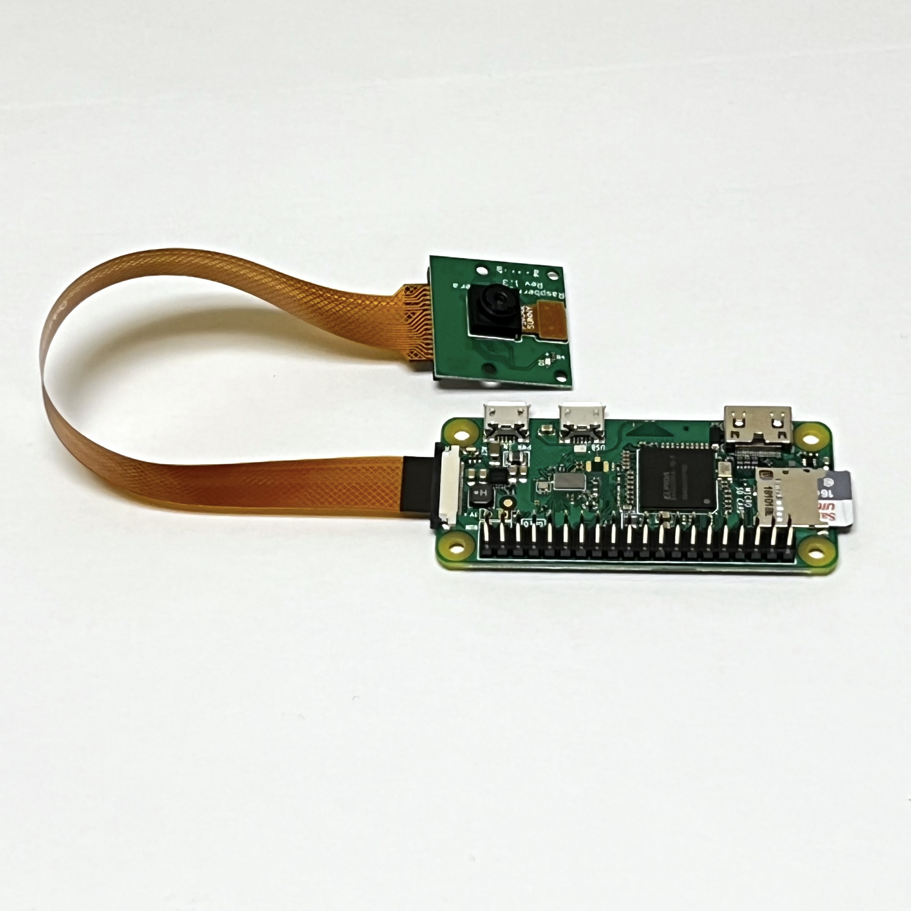
Note that the LED on the Pi Camera will blink once when the Pi Zero boots up and whenever it takes a photo.
Testing the Pi Camera
To test the camera, log into your Pi Zero. If you can connect the mini HDMI output from the Pi Zero to a HDMI monitor, that is helpful.
Type this command:
cd
raspistill -o test.jpg
After about 30 seconds, the image should be stored as test.jpg. To see the image file, type:
ls -all test.jpg
The size should be non-zero.
To view the image on your computer, you will need to get your computer on the same WiFi as the Pi Zero (CubeSatSim is the default WiFi SSID) then do a file transfer from your computer.
You will need to bring up a command prompt then type this on your computer (this assumes Group A - put your Group's letter after cubesatsim in this command):
scp pi@cubesatsima:/home/pi/test.jpg .
You will be prompted for the password of your Pi (raspberry) then the file should transfer. Double click on the test.jpg on your computer image and you should see it on your computer.