V1.3.2 Adding New Sensors to STEM Payload Board - alanbjohnston/CubeSatSim GitHub Wiki
This page describes how to add new sensors to the STEM Payload Board.
First, you will need to wire your sensor to the STEM Payload board. Most sensors are I2C, and the easiest way to add them is to use one with a Qwiic connector on it. The STEM Payload board has a Qwiic connector, so you will just need a Qwiic sensor and cable such as these: https://www.sparkfun.com/qwiic Alternatively, you can wire it up manually.
Secondly, you will need to install the Arduino IDE software so you can compile the STEM Payload code that runs on the Raspberry Pi Pico microcontroller.
Blink Test
To do the blink test, you need to program your microcontroller. Here are the basic instructions for the Raspberry Pi Pico or Pico W.
I'd recommend using the Arduino Integrated Development Environment (IDE) application to program your Pico, although you can use other IDEs too. Use the 1.8.x version instead of the new version 2 since the new version has some issues with the Pico board. Download it here: https://www.arduino.cc/en/software You will need to scroll down to find the "Legacy IDE (1.8.X)" version to download.
You can even install the Arduino IDE on your Raspberry Pi Ground Station using the "Linux 32 bits" version.
Before you can program your Pico using the Arduino IDE application, you will need to install the board files for the Pico. First, you need to go under Arduino then Settings to open the Preferences and look for the he Additional Boards Manager URLs field. Type this URL https://github.com/earlephilhower/arduino-pico/releases/download/global/package_rp2040_index.json into the Additional Boards Manager URLs field:
Select OK. Then open the menu Tools/Board/Boards Manager which will open the Boards Manager. In the search box, type pico then return. You will see the Raspberry Pi Pico/RP2040 by Earle F. Philhower, III Board file which supports the Raspberry Pi Pico and Pico W board.
Click Install and after a few minutes it will show as Installed.
Close the Boards Manager. Now open the Blink example code under the menu File/Examples/01.Basic/Blink and open this sketch.
Go under the Tools menu and select Board and select Raspberry Pi RP2040 Boards. You also need to select the correct version of the board. Select the Raspberry Pi Pico W (this will work even if you have a Raspberry Pi Pico without WiFi). If your Pico has never been programmed, you won't need to select the Port. Instead, you will notice a USB flash drive called RPI-RP2 that has mounted on your computer.
Click the Verify icon (check symbol) at the top to Compile the code. If that works, click the Upload icon (arrow pointing right) to upload it to the Pico. You may get a popup about a drive being unplugged - just ignore this, it is normal. If all goes well, the built-in LED in your Pico should be blinking on and off!
Now if you look under Tools/Port you will see a new port labeled Raspberry Pi Pico W. You may have to select this port manually in the future after you plug in your Pico to reprogram it.
If the Upload fails with an error, you might need to manually select the Port. Under menu Tools/Port look for one that says Raspberry Pi Pico W and select it. If you can't find it, try unplugging the Pico, noting the ports listed, then plugging it back in. The new port listed will be the Pico.
If you have difficulty programming your Pico, see the notes here: https://github.com/earlephilhower/arduino-pico#installing-via-arduino-boards-manager
Payload Sensor Testing
You can now test that the Pico can communicate with the two sensor boards. Here is the code (sketch) that runs on the Pico:
This code requires several libraries which you will need to install. If you forget to install one or more libraries, you will get error messages saying "No such file or directory" when you Verify or Upload the code.
Open Tools/Manage Libraries and the Library Manager will open after a few moments. In the search box, type bme280 then return and you will see the Adafruit BME280 library. When you mouse over it, it will give a version pulldown menu and an Install button. Select version 1.1.0 and click on Install to install it. You will be prompted to install a few other library dependencies as well - select Install All. It should look like this when it completes:
Next, type tockn then return in the search box and install the MPU6050_tockn library and click Install to install it. Type tinygpsplus into the search box and install this library as well.
Click Close to close the Library Manager. In the sketch window, click on the Verify icon (checkbox) and it should compile without errors.
If you get an error saying "No such file or directory", go back to the Library Manager and make sure you have installed the correct version of all three libraries. Click on the Upload button (right arrow) and the Pico should be programmed to read the sensors.
Once it is done uploading (indicated by the Done Uploading) message at the bottom of the window, open the Serial Monitor by clicking on the magnifier icon in the top right of the window. You should get a response displayed similar to this updated every second or so:
OK BME280 24.89 1003.96 77.61 21.13 MPU6050 -0.85 -2.48 -1.09 0.19 -0.15 1.02 GPS 0.0 0.0 0.0 TMP 22.3
The OK is the status response. The four numbers after the BME280 are the temperature in Celsius, pressure in hPa, altitude in meters, and humidity in percentage read from the purple BME280 sensor. The six numbers after the MPU6050 are the X, Y, and Z axis angular rotation in degrees per second and the X, Y, and Z axis acceleration in g. If you get a series of zeros after a sensor, it means it was not successfully read by the Pico. The three numbers after GPS are GPS latitude, longitude, and altitude which will be zero unless you have connected a GPS module to your board. After the TMP is the temperature estimated from the diode D3.
On the Raspberry Pi, you can also use the CubeSatSim/config -p command to see the sensor data from the Pico.
If you get all zeros for a sensor, you need to determine if it is a hardware or software problem. Running an I2C bus scanner program will tell you if the sensor can be accessed on the I2C bus. The program is:
https://github.com/alanbjohnston/CubeSatSim/tree/master/stempayload/i2c_scanner
Upload this to your Pico and then open the Serial Monitor. You should see:
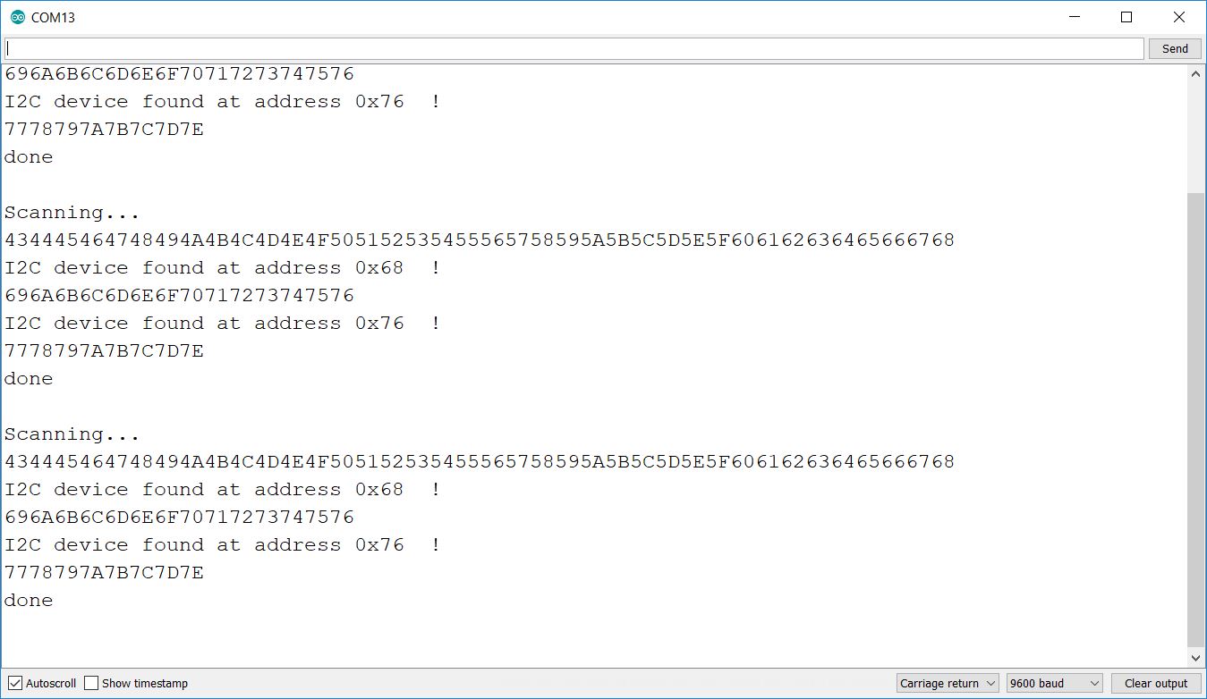
The blue MPU6050 should be at address 0x68 while the purple BME280 should be at address 0x76. If neither device is present on the I2C bus, make sure resistors R23 and R24 are soldered in and are 4.7k Ohms in value. If one sensor shows up but not the other, it might be due to soldering on the sensor pins or due to a bad sensor board.
If both sensors show up on the I2C bus but you get zeros in the Serial Monitor, this indicate a software problem.
Adding Sensors
You are now ready to start adding sensors to the code.
Click on the tab "payload_extension.cpp" and you will see where you add the code for your sensor:
There is an example in Payload_BME280_MPU6050_XS_Extended that you can use as a template.
Once you have added your code, simply compile and Upload to your Pico. You should see the new sensor at the end of the string in the Serial Monitor and in the APRS packet when it is decoded.
On the Raspberry Pi, you can also use the CubeSatSim/config -p command to see the sensor data from the Pico.