Testing - alanbjohnston/CubeSatSim GitHub Wiki
Testing your CubeSatSim can be done once your build is complete, or you can test at intermediate points. Testing as you go along can be good in that it will give you confidence in your work, and also can save you time in troubleshooting since some functions have tested OK and can be eliminated as possibilities.
The tests are labeled for reference.
Step 1 Build
Before any tests can be done, you at least need to have these components installed, which we will call Step 1:
-
GPIO header
-
Red, Green, and Blue LEDS
-
Push Button
-
1k Ohm resistor R8
-
BPF
-
micro USB connector
-
Protection diode D9
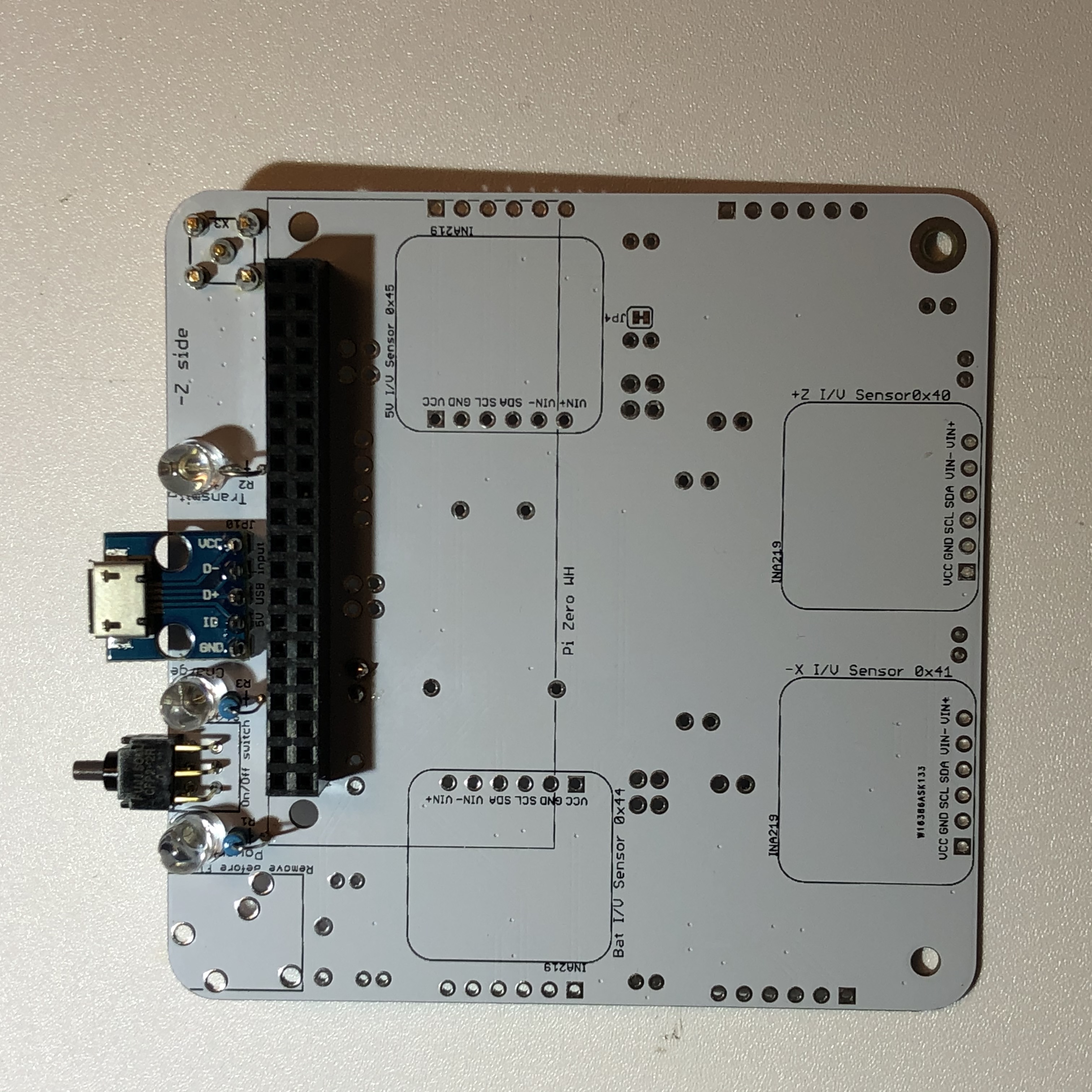
Here is an example Step 1 Build board
In addition, these tests require the software to be installed.
Pi Test
With the Pi plugged into the Step 1 Build and powered directly via the Pi USB port, the Pi will turn on and the tiny green LED on the Pi will be on or blinking.
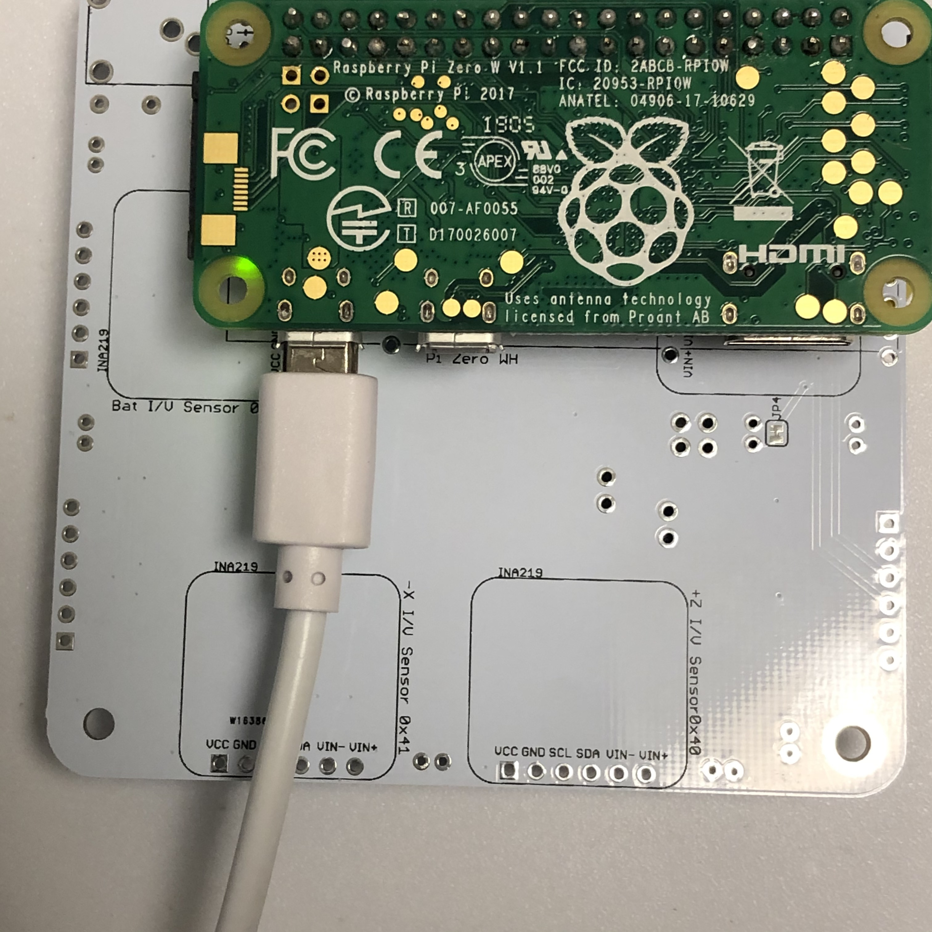
IMPORTANT NOTE: If your CubeSatSim is built beyond Step 2, DO NOT plug the USB power directly into the Pi - this could damage it. Instead, to do this test just use battery power as shown here
If the Pi does not turn on, make sure your USB cable and power plug are functioning and plugged directly into the Pi (i.e. not plugged into the CubeSatSim board). Make sure the Pi has a micro SD card with the Raspbian operating system installed. Otherwise, check the installation of the GPIO header for short circuits.
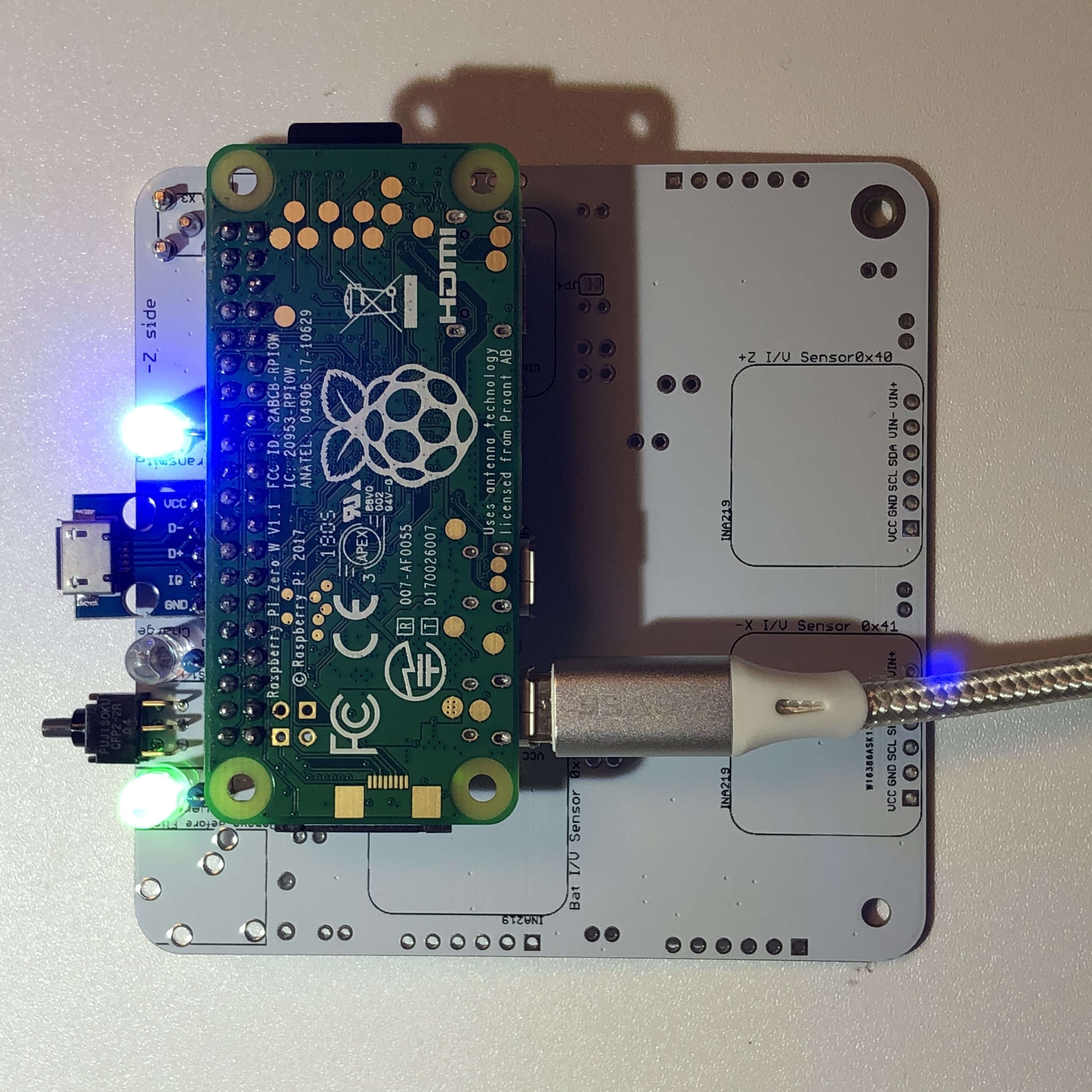
Green LED Test
With the Pi plugged into the main board and powered directly on the micro USB port, after booting, the CubeSatSim software will run and turn on the green LED.
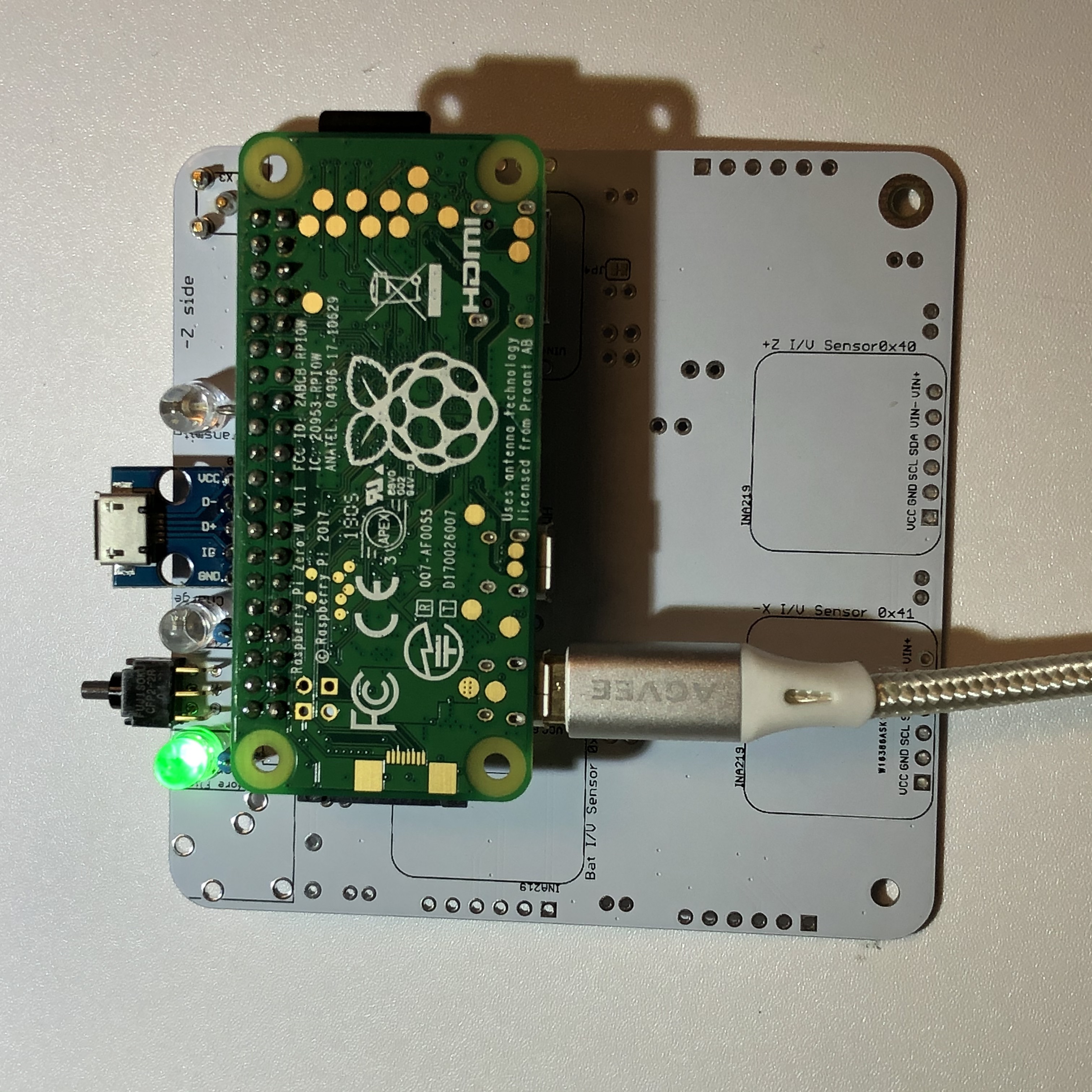
IMPORTANT NOTE: If your CubeSatSim is built beyond Step 2, DO NOT plug the USB power directly into the Pi - this could damage it. Instead, plug the USB power cord into the Main board or run on battery as shown here
If the LED doesn't illuminate, it might mean there is a problem with the LED circuit or that the software isn't running.
Push Button Test
With the Pi plugged into the main board and powered directly on the micro USB port, after booting, the cubesatsim software will run. When the push button is pressed and held, the green LED should blink. When pressed and immediately released, the Pi should reboot. When pressed and held until the green LED flashes slowly, the Pi should shutdown (the tiny green LED on the Pi will flash then go out).
If the green LED doesn’t blink, there might be a problem with the push button install or with the pi-power-button software.
Blue LED Test
With the Pi plugged into the main board and powered directly on the micro USB port, after booting, the CubeSatSim software will run. When the CubeSatSim is transmitting, the blue LED will be illuminated, occasionally blinking. This indicates that the CubeSatSim is transmitting.
IMPORTANT NOTE: If your CubeSatSim is built beyond Step 2, DO NOT plug the USB power directly into the Pi - this could damage it. Instead, to do this test just use battery power or the USB power cable plugged into the Main board as shown here
If the blue LED doesn’t illuminate, it might mean there is a problem with the blue LED install or the software.
Transmit Test
If the blue LED is illuminated, you can tune your radio or SDR to 434.9 MHz to see if you see a signal. If your pushbutton is working, you can try the three different modes: AFSK, FSK, and BPSK - you can see and hear the difference on your radio. If you have your FoxTelem ground station working, you can try to decode frames in FSK and BPSK modes.
If your blue LED is illuminated but you don't see a signal, check your antenna on the CubeSatSim, antenna on your radio or SDR, and the gain and frequency on your SDR or radio. Or there may be a problem with the rpitx transmit software.
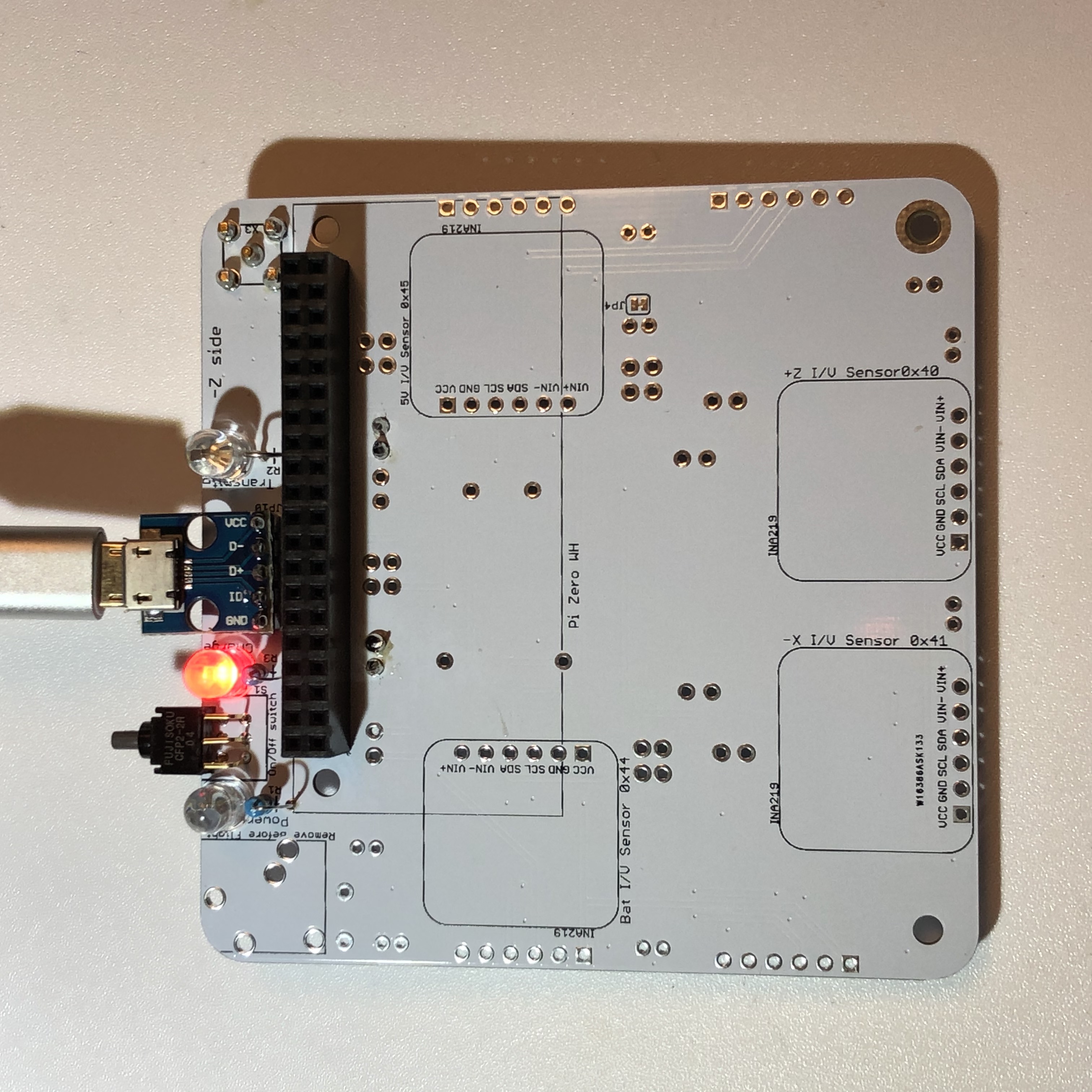
Red LED Test
You don't need the Pi plugged in or powered up for this test, but you do need the micro USB connector installed and a charging cable plugged into a computer or a power outlet. When the charging cable is plugged in, the red LED will illuminate.
If it doesn't illuminate, check the red LED circuit, micro USB connector, or your power cable.
Step 2 Build
The Step 2 Build has Step 1 build complete plus these components:
-
At least one I/V Sensor board, e.g the +X board (could also be the -X, +Y, -Y, +Z, or -Z I/V Sensor)
-
At least one solar panel and cable built
-
At least one diode associated with the I/V Sensor board if it is for a Solar Panel (the Battery and 5V Bus I/V Sensors do not need a diode to function). e.g. D9 for the +X I/V Sensor board.
-
At least one JST connector for the I/V Sensor board e.g +X Solar connector.
-
Two 4.7k Ohm resistors as R4 and R6
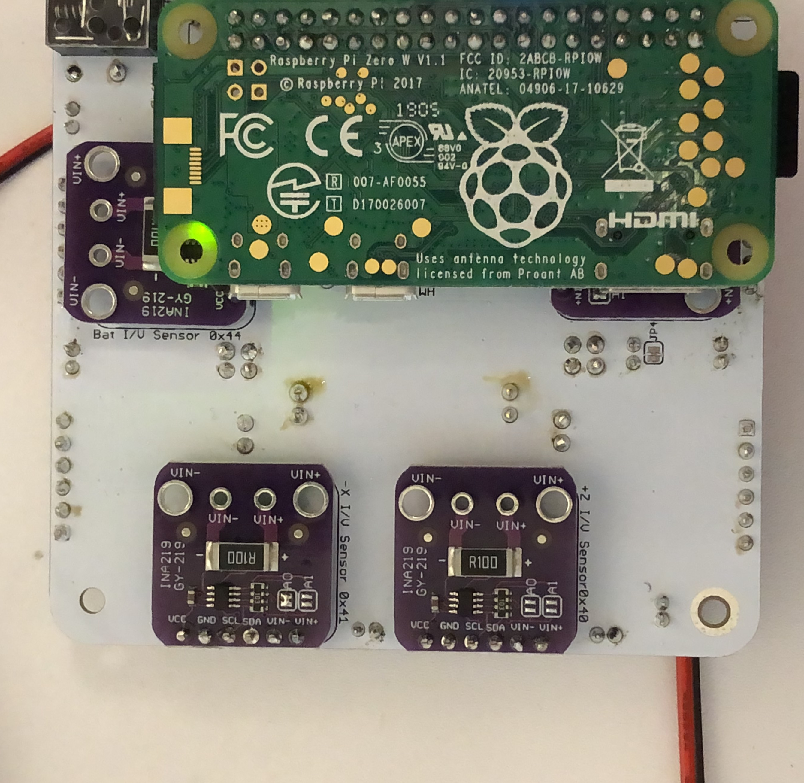
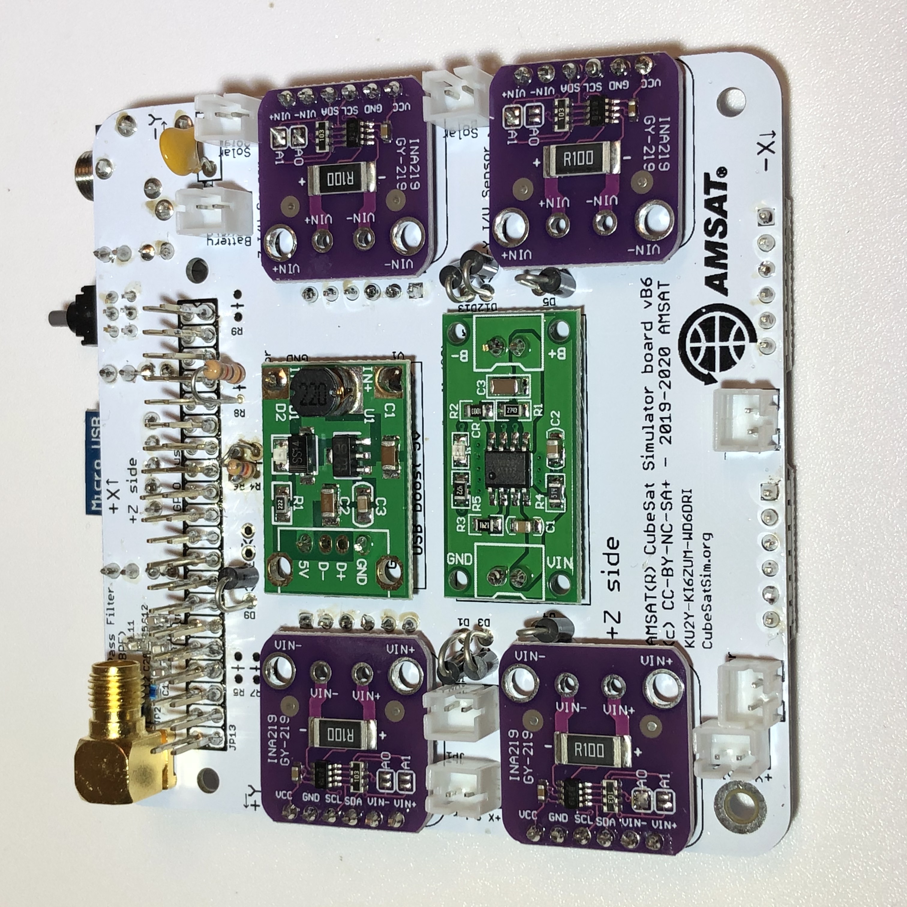
Here is an example Step 2 Build board
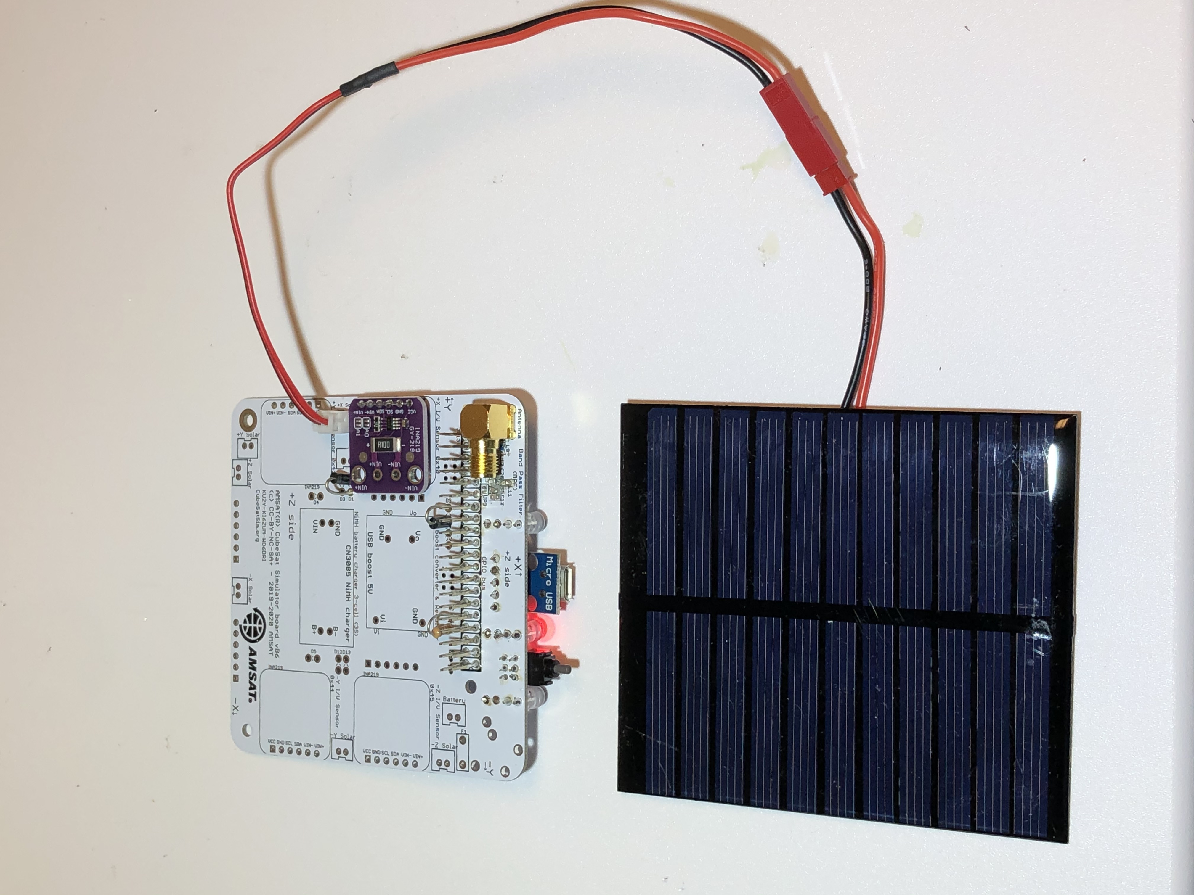
Solar Panel Test
You don't need the Pi plugged in or powered up for this test, but you do need the solar panel plugged into the JST connector and illuminated with light. The red LED will illuminate.
If the LED doesn’t illuminate for the solar panel but it does illuminate for the USB cable, check the Solar Panel wiring and connector for continuity and correct polarity.
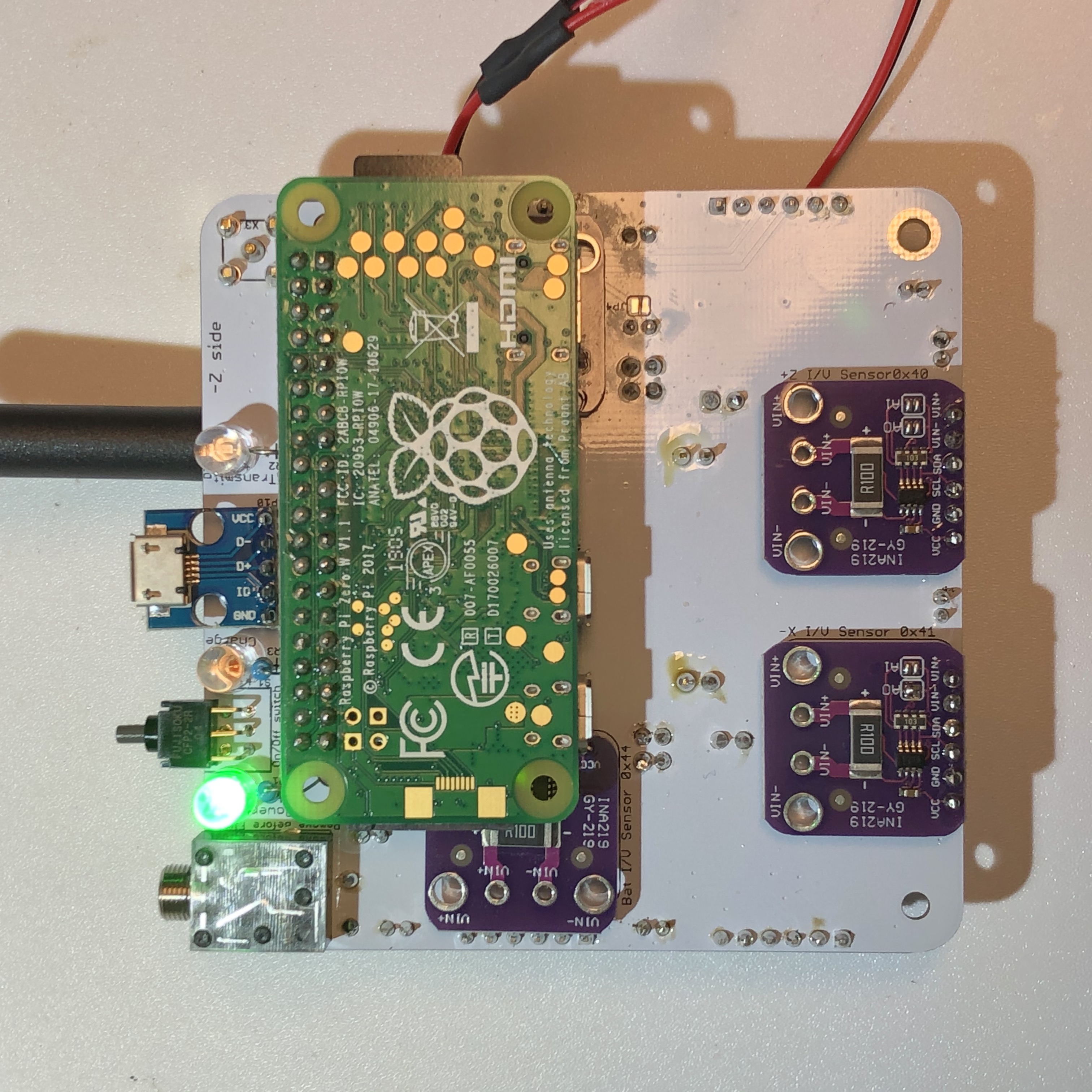
Solar Panel Voltage Sensor Test
With the Pi plugged into the main board and powered directly on the micro USB port, after booting, the CubeSatSim software will run. If you have installed the Battery I/V Sensor, you will need to first do the Battery Sensor Test below as the CubeSatSim might shutdown as soon as it starts up due to sensing a low battery voltage.
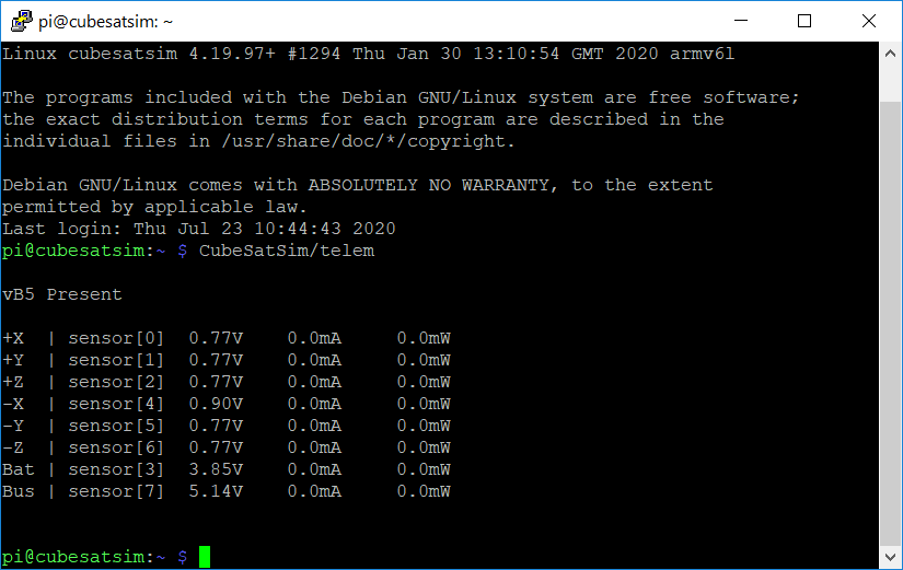
Open a terminal window in the Pi and type
CubeSatSim/telem
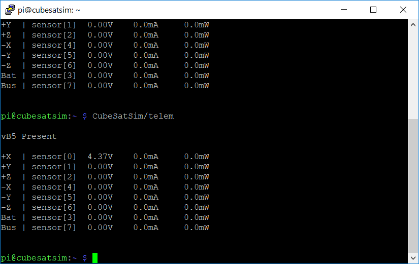
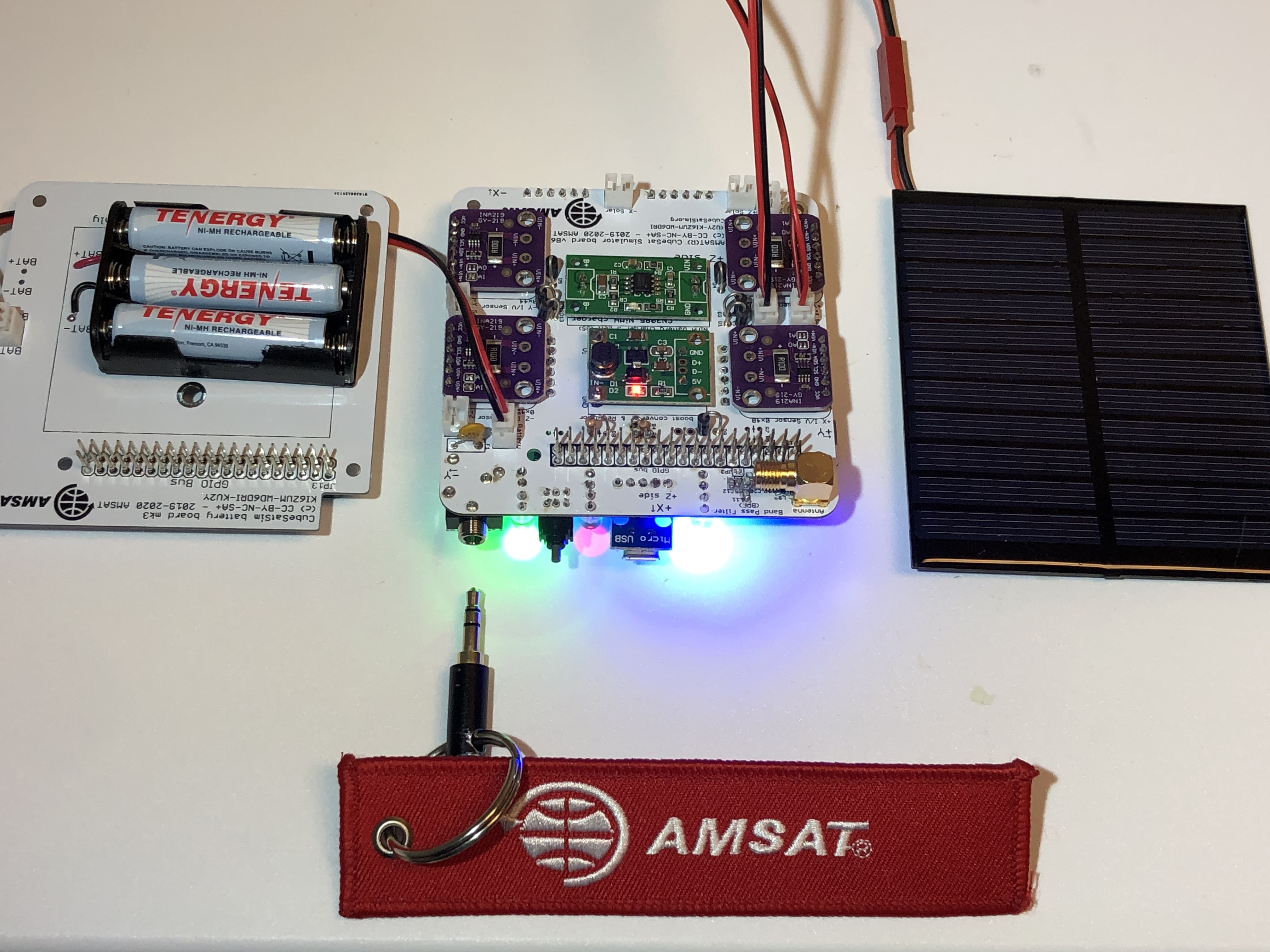
and you should see a non-zero voltage for each I/V Sensor that is installed. If you have a Solar Panel plugged into an I/V sensor and it is illuminated, you should see a voltage greater than 2V. For example, this shows only the +X I/V Sensor installed and a Solar Panel plugged into it:
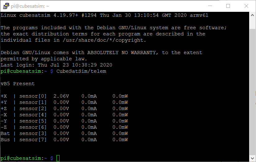
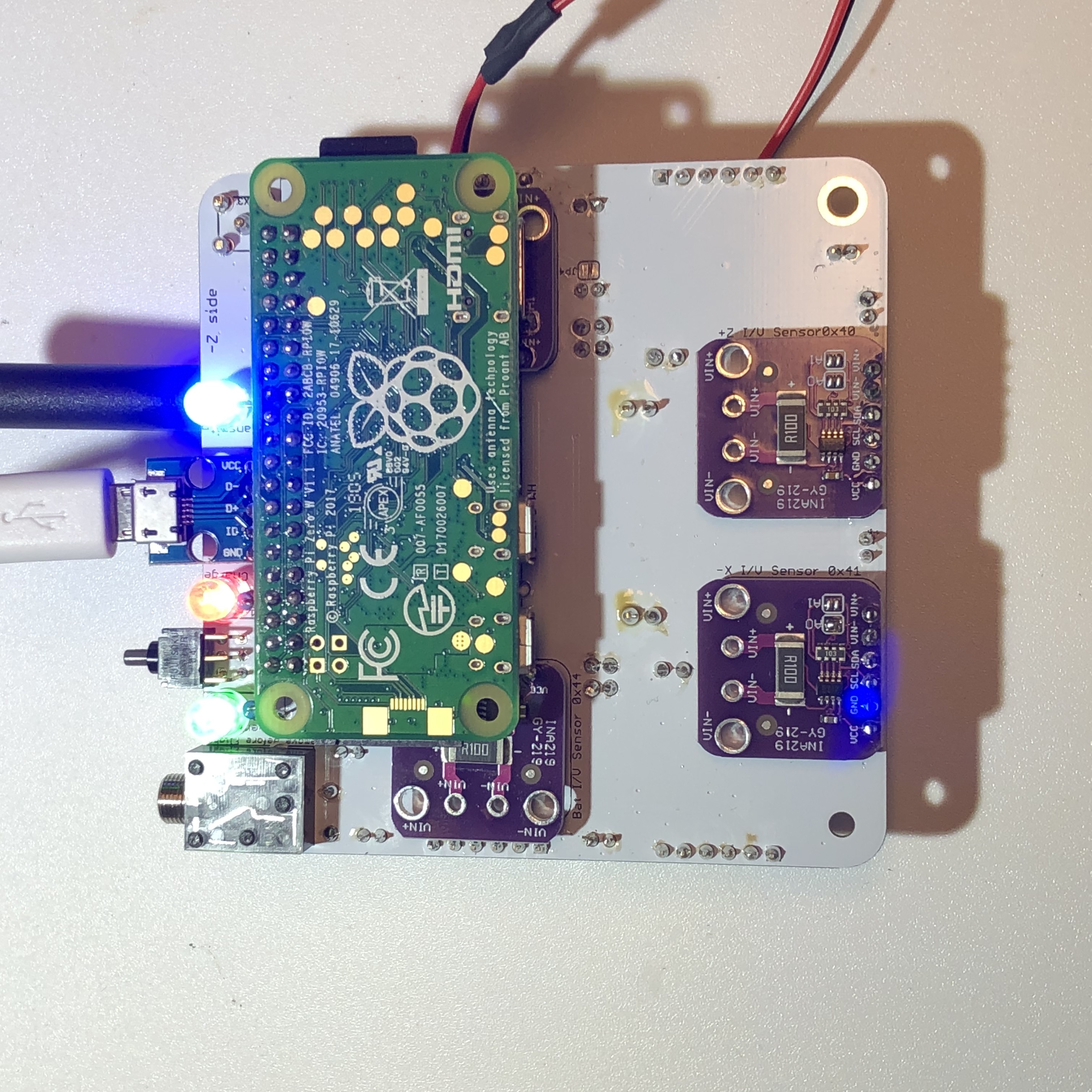
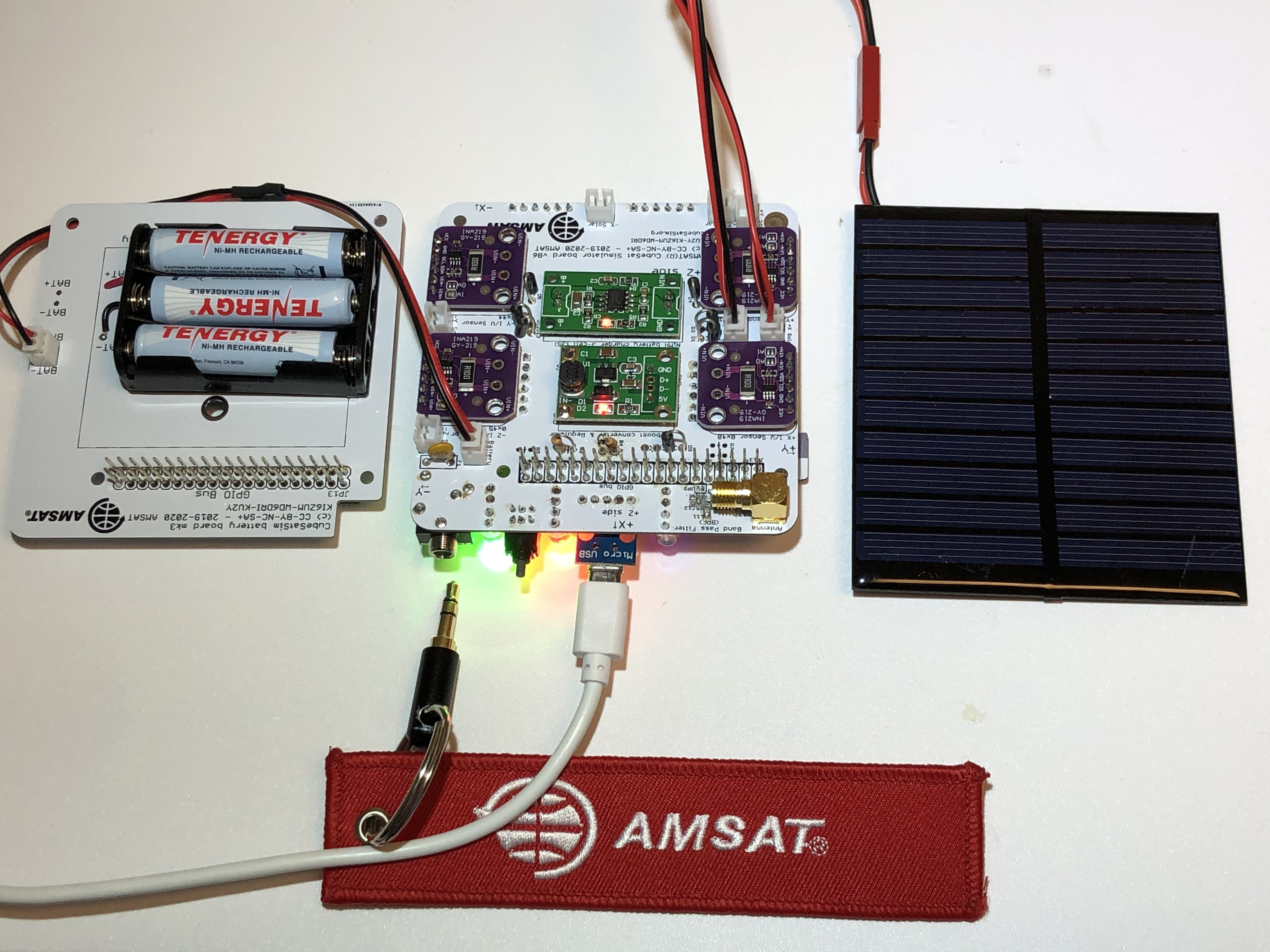
And this time with stronger illumination:
If you see an error displayed, the I2C configuration on the Pi might be incorrect. If you don’t get a voltage, there might be a problem with the I/V Sensor such as the wrong address setting.
Battery Voltage Sensor Test
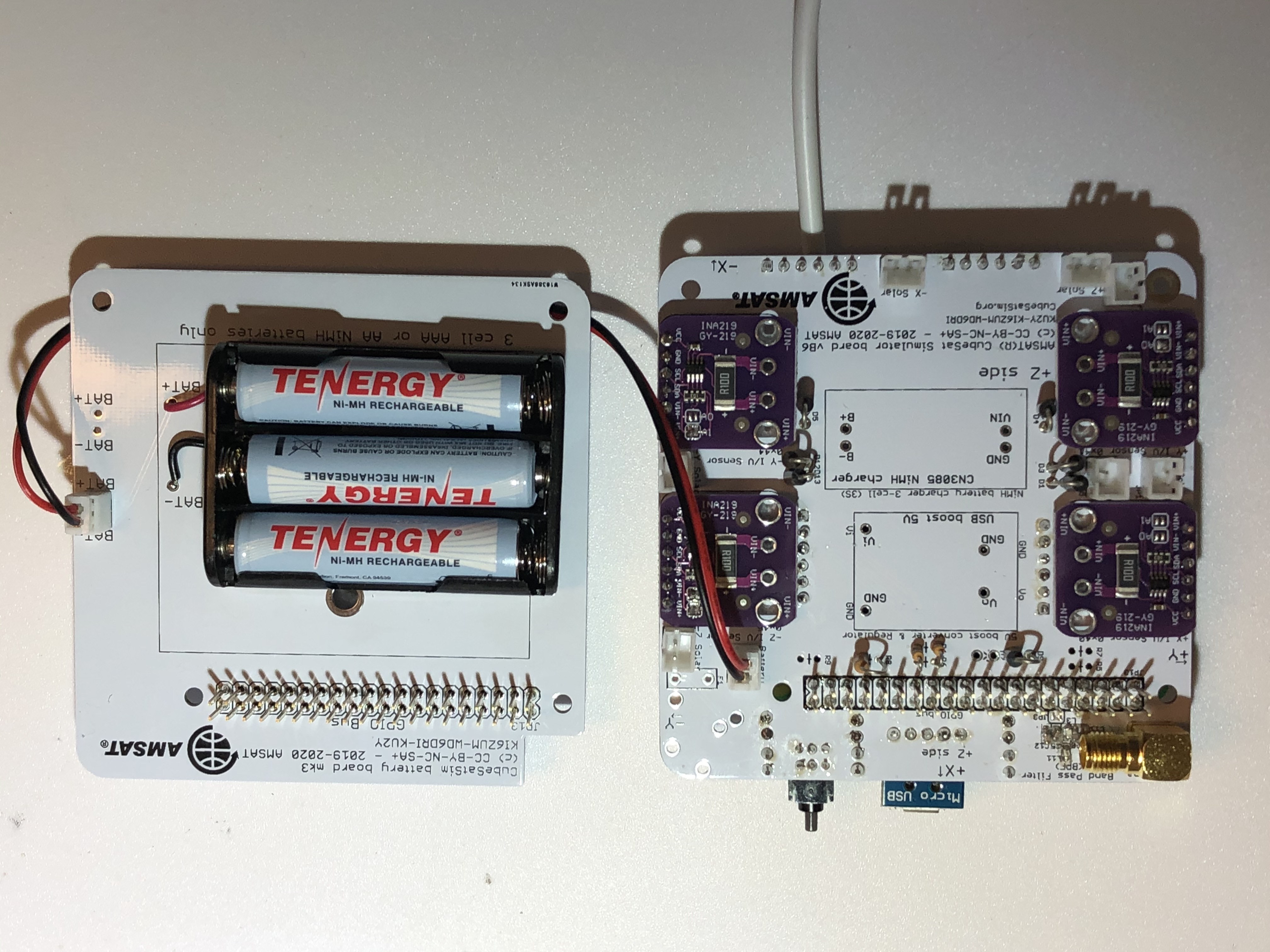
If your Battery Board is built, you can test the Battery I/V sensor with the battery plugged in:
First power up the Pi without it plugged into the Main Board. In the terminal window type:
sudo systemctl disable cubesatsim
This will stop the CubeSatSim software so that the Pi will not be shutdown if your battery voltage is low. Next, shut down the Pi by typing:
sudo shutdown now
Once the Pi is shutdown, plug it into the Main board and plug and press the pushbutton to start it up. The green and blue LEDs will not illuminate since the CubeSat software isn't running. Open a terminal window in the Pi and type
CubeSatSim/telem
and you should see a non-zero voltage for each I/V Sensor that is installed and a voltage for the Battery between 3V and 4.5V. For example, this shows all six I/V Sensors installed and a battery plugged in.
The current will read zero since you are powering the Pi directly, not through the Main Board. When you are done testing, restart the CubeSatSim software by typing:
sudo systemctl enable cubesatsim
The software will start the next time the Pi turns on.
If you don’t get a voltage, there might be a problem with the Battery I/V Sensor such as the wrong address setting. Or, there might be a problem with your Battery Board such as an incorrect wiring or polarity, or a battery cell popped out or reversed.
5V Bus Voltage Sensor Test
With the Pi plugged into the main board and powered directly on the micro USB port, after booting, the cubesatsim software will run. If you have installed the 5V Bus I/V Sensor, you can test it by opening a terminal window and typing:
CubeSatSim/telem
You should see a voltage close to 5V for the Bus as shown above. The current will read zero since you are powering the Pi directly, not through the Main Board.
If you don’t get a voltage, there might be a problem with the 5V Bus I/V Sensor such as the wrong address setting.
Step 3 Build
This a complete build with the components in Step 1 and Step 2 plus these components installed:
-
Battery Charging board
-
5V Boost Converter and Regulator board
-
RBF switch and plug
-
PTC resettable fuse and Zener protection diode
For these tests, use an arrangement known as a "flat sat" where the various CubeSat boards are connected side by side instead of stacked so you can get access to everything.
Running Test
When you unplug the RBF pin, you will see a small red LED on the 5V Boost Converter and Regulator board and the Pi will turn on (the small green LED on the Pi will blink). The green LED will turn on and the blue LED will occasionally blink if the CubeSatSim software is running. If you illuminate a Solar Panel, the red LED will illuminate.
If you have the FoxTelem Ground Station running, you can verify the Battery Voltage and Current, and the PSU Voltage and Current in the CubeSatSim FSK Health Tab.
If the CubeSatSim doesn’t power up, make sure your battery is plugged in correctly and is at least 3.2 V (the CubeSatSim will not turn on if no battery is connected). Make sure nothing is getting hot or overheated including the Pi.
Charging Test
When you plug in the micro USB cable connected to an outlet, the red LED will illuminate and a small red LED will illuminate on the Battery Charging Board.
In FoxTelem, the Battery Voltage will jump up and the Battery current will be negative, indicating the current is flowing into the battery to charge it. If the battery is discharged, this could be around 300 mA, or less than 100 mA for a fully charged battery.
If you don’t get charging or the charging LED doesn’t illuminate, there might be a problem with the Charging Board or your USB charging cable or outlet. If the RBF pin is not inserted, charging will always happen, even if the battery is fully charged. Only if the RBF pin is inserted and the battery is fully charged will charging stop.
Solar Panel Current Sensor Test
In FoxTelem or using telem command line, verify that each Solar Panel (+X, -X, etc) generates current under sunlight or halogen illumination.
If no current flows, make sure the Solar Panel is getting good illumination from the sun or halogen lamp. Only the most powerful LED lamp (greater than 9W) will generate a current. Getting a voltage from each panel does not guarantee that current will flow.
STEM Payload Communication Test
With the STEM Payload programs with the PayloadOK sketch, the Pi will communicate with the STM32 at startup. If communication is successful, a flag is sent over the telemetry so that FoxTelem in FSK mode will show under Experiments that STEM Payload is OK.
If you don’t see OK, verify that FoxTelem is decoding live packets. Make sure the STEM Payload board is plugged in and the power LED illuminated. Make sure the PayloadOK sketch is programmed.
RBF Switch Test
Verify that when shutdown, removing the RBF pin makes the CubeSatSim turn on. Also when shutdown, verify that pressing the push button does not start the CubeSatSim when the RBF pin is in.
If removing the RBF pin does not start the CubeSatSim, make sure the battery is connected and not fully discharged. Make sure the Pi is plugged in and has a programmed micro SD card. If the RBF inserted does not prevent the CubeSatSim from starting, check the installation of the RBF switch.
Results
If your CubeSatSim has passed all these tests, congratulations, the status of your CubeSatSim is “nominal” :-)
Note: For a spacecraft, “nominal” means fully functioning with no anomalies or problems.