Solar Power Board Testing Instructions - alanbjohnston/CubeSatSim GitHub Wiki
These are the instructions for testing and configuring the Solar Power Board.
Putting it all together and Testing
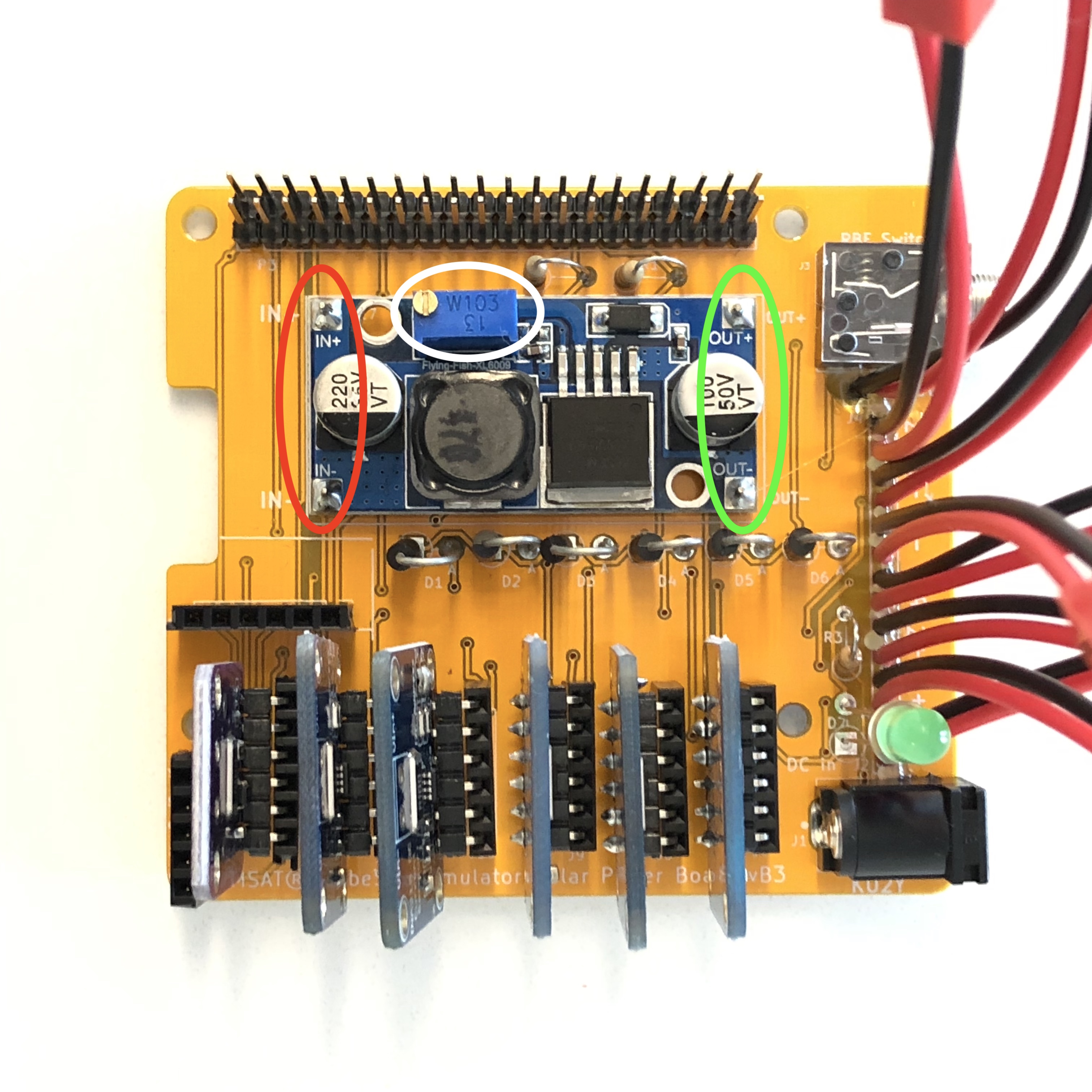
- Before you plug the Solar Power Board into the Three Board Stack, you need to adjust the Boost Converter. Plug in one solar panel (the +Z panel on the top of the frame is convenient) to the +X connector on the Solar Power Board. Illuminate at the solar panel (if you are using a halogen light, be careful not to get it too hot - keep a safe distance between the lamp and the Simulator). With the RBF pin removed, measure the voltage between IN+ and IN- on the left side of the Boost Converter module (U1), as shown circled in red here:
You should measure around 3 Volts. If you read 2 Volts or lower, try moving the solar panel closer to the halogen lamp (don't put it too close or the plastic might melt!).
-
Measure the voltage between OUT+ and OUT- on the Boost Converter module, shown circled in green in the image above. You will read a voltage above 20 V. Find the trimpot voltage adjustment on the Boost Converter module, U1, circled in white in the above image. Adjust the trimpot using a jewelers screwdriver or trimpot adjuster so that the voltage between OUT+ and OUT- is around 15V. Turning clockwise will reduce the output voltage. It may take approximately 3 turns. Put the RBF pin back in, and the voltage between OUT+ and OUT- should drop to zero. Your Boost Converter is now adjusted.
-
Plug the Three Board Stack into the Solar Power Board board. The complete stack should now look like this.
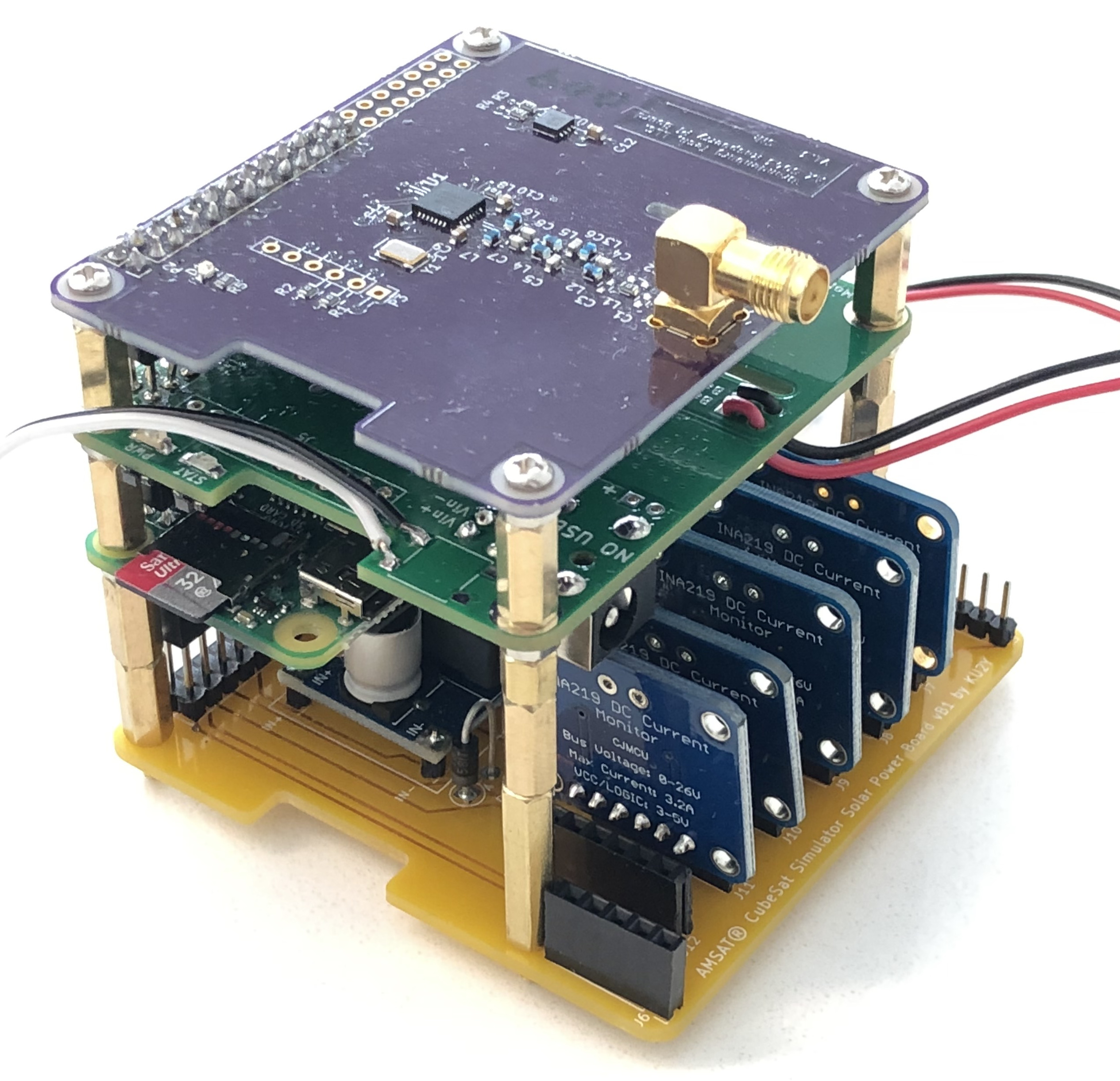
Use four 5mm standoffs under the Solar Power Board to secure it to the three board stack:
- Power up the Pi and make sure everything seems OK. Run
i2cdetect -y 1command on Pi. You should see each INA219 Board you have plugged in (40, 41, and 44, and 45 for J7, J8, J9, and J10):
. . 00 01 02 03 04 05 06 07 08 09 0a 0b 0c 0d 0e 0f
00: . . . . -- -- -- -- -- -- -- -- -- -- -- -- --
10: -- -- -- -- -- -- -- -- -- -- -- -- -- -- -- --
20: -- -- -- -- -- -- -- -- -- -- -- -- -- -- -- --
30: -- -- -- -- -- -- -- -- -- -- -- -- -- -- -- --
40: 40 41 -- -- 44 45 -- -- -- -- 4a -- -- -- -- --
50: -- -- -- -- -- -- -- -- -- -- -- -- -- -- -- --
60: -- -- -- -- -- -- -- -- -- -- -- -- -- -- -- --
70: -- -- -- -- -- -- -- --
(If you have the Current Sensor module included in the MoPower UPS V2 board, you will also see it at 4a as well). If not, check A0 and A1 jumpers and soldering of the missing board. If i2cdetect -y 1 returns all dashes, check to make sure that two of the GPIO connector pins (pins 3 and 5) on the MoPower UPS board are bent so that when you plug the Digital Transceiver board into it, they do not make contact. Run i2cdetect -y 0 command on the Pi to get:
. . 00 01 02 03 04 05 06 07 08 09 0a 0b 0c 0d 0e 0f
00: . . . . -- -- -- -- -- -- -- -- -- -- -- -- --
10: -- -- -- -- -- -- -- -- -- -- -- -- -- -- -- --
20: -- -- -- -- -- -- -- -- -- -- -- -- -- -- -- --
30: -- -- -- -- -- -- -- -- -- -- -- -- -- -- -- --
40: 40 41 -- -- -- -- -- -- -- -- -- -- -- -- -- --
50: -- -- -- -- -- -- -- -- -- -- -- -- -- -- -- --
60: -- -- -- -- -- -- -- -- -- -- -- -- -- -- -- --
70: -- -- -- -- -- -- -- --
You should see the other INA219 Board you have plugged in (40 and 41 for J11 and J12). If not, check A0 and A1 jumpers and soldering of the missing board.
If one INA219 board is missing, remove that board and check the AO and A1 jumpers are set correctly. If you have a spare INA219 board, try plugging it in, after setting the correct values. If it is a 0x40 or 0x41 board, try swapping it with the 0x40 or 0x41 board on the other bus. If one of the buses shows no devices or shows a random set of devices, unplug all the devices from that bus (e.g. if it is bus 1, then unplug boards from J7 - J10, if bus 0, unplug boards from J11 and J12). Plug the boards in one at a time to see if any show up. If none show up, check the board for a short on the SCL or SDA signals (see schematic). Try plugging in a board from the other bus. If you have an Arduino, you can run a slave sketch code on it and connect it following the instructions on the Arduino Payload to connect the Arduino on the Expansion Interface J6.
- Check to make sure the CubeSat Simulator software is up to date. Type:
cd ~/CubeSatSim
git pull
If you get any message other than "Already up-to-date" then type make to generate new executable files.
Next, run the sensor only software on the Pi:
python ~/CubeSatSim/python/telem.py
You should see results for all the boards. Plug in an illuminated solar panel into J1 for +X (pin 1 to + and pin 2 to -) and rerun the Sensor only software - you should see the +X voltage (open circuit voltage of the solar panel), and current (approximately zero) and power (approximately zero). Repeat for +Y, +Z, -X, and -Y (if you have them) (pins 3 and 4, pins 5 and 6, pins 7 and 8, and pins 9 and 10). For example, with just one solar panel plugged in, you might see:
+X (0x40) v= 3.772 V i= -0.0914634146341 mA p= 0.0 mW
+Y (0x41) v= 1.32 V i= -0.0914634146341 mA p= 0.0 mW
+Z (0x44) v= 1.3 V i= 0.0 mA p= 0.0 mW
Battery (0x45) v= 0 V i= 0 mA p= 0 mW
5V Supply(0x4a) v= 5.088 V i= 200.0 mA p= 849.085365854 mW
-
With the RBF pin plugged in, plug in the DC in barrel power cable into the Solar Power Board (from now on you won't plug it directly into the MoPower board unless the Solar Power Board is unplugged from the stack).
-
Connect the Vin2 connector on the MoPower board (female JST RCY connector) to Vout J4 on the Solar Power Board (male JST RCY connector). With the DC power plugged into the Solar Panel Board and the RBF pin plugged in, verify that the battery pack is charging by typing:
mpcmd ADC_VIN_VOLTS
You should see a voltage such as this:
*ADC_VIN_VOLTS=15.120
which indicates that the battery is charging by the DC power pack through the Solar Power Board. Check the battery voltage by typing:
mpcmd ADC_VBATT_VOLTS
You should see a value between 9 and 7.5 Volts. If it is close to 7.5 Volts, you should keep the DC power pack plugged in to charge for a while until the battery voltage is above 8 V.
-
Remove the RBF pin and with the solar panels not illuminated, read the input voltage again by typing
mpcmd ADC_VIN_VOLTS. You should see a voltage close to zero. Illuminate at the solar panel, and check the charging voltage by typingmpcmd ADC_VIN_VOLTS. You should read a voltage that is slightly lower than the battery voltage - this indicates that the solar panel is supplying power to the Simulator. Plug the RBF pin back in. -
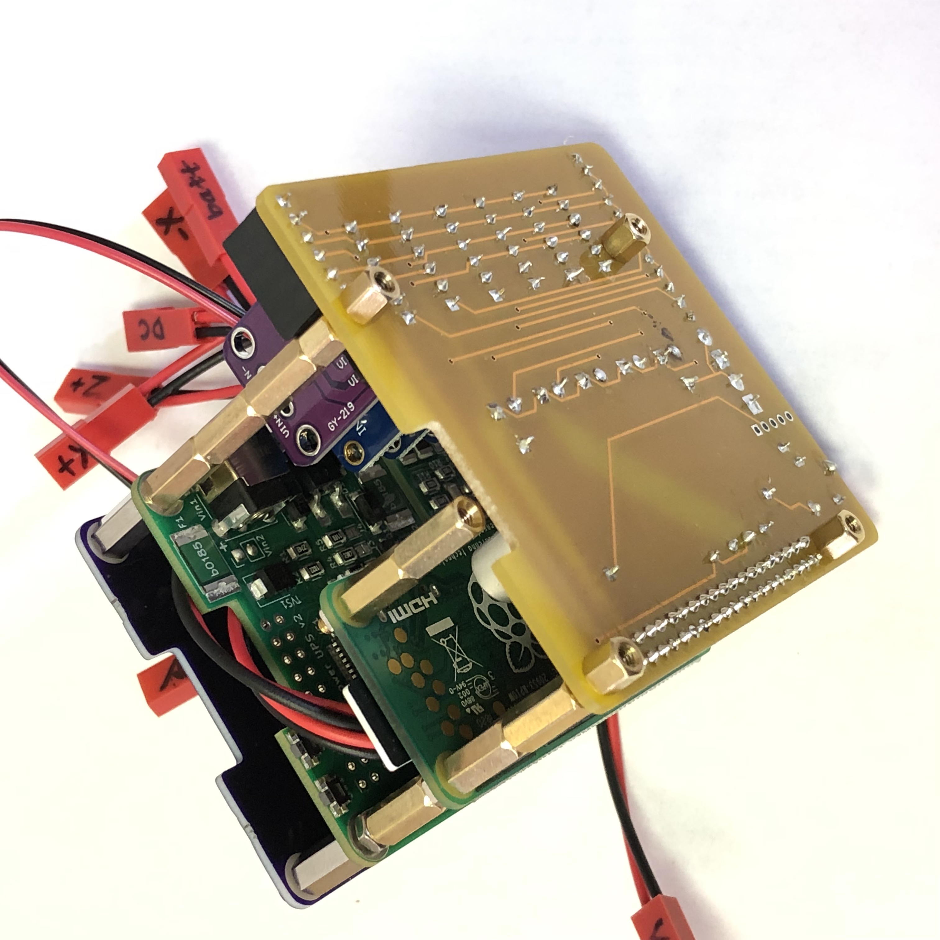
Unplug the battery from the MoPower board and plug it into one connector of the Battery Monitoring cable. Measure the voltage at the other connector of the Battery Monitoring cable. You should read around 9 V, positive is the smaller connector, negative, the larger connector. If the voltage and polarity are correct, plug this end of the Battery Monitoring cable into the MoPower battery connector. The two 9 V connectors will be back to back as shown here.
- Check the voltage by typing
mpcmd ADC_VBATT_VOLTSto verify that it is connected. Run the Sensor only softwarepython ~/CubeSatSim/python/telem.pyand you should see a row for the battery:
Battery (0x45) v= 9.472 V i= -6.29268292683 mA p= 59.2682926829 mW
You might see a voltage for the battery which is very close to zero (e.g. something like v= 0.03212) in which case you need to unplug the battery and the MoPower board and switch the connectors - then you should see both a voltage and current. A negative current indicates that the battery is being charged. Unplug the DC power in or remove the RBF pin with the solar panels not illuminated. If you see a battery voltage but close to zero current, there might be a short on your board - check the soldering. Check the battery voltage again with python ~/CubeSatSim/python/telem.py and you should see something like:
Battery (0x45) v= 9.092 V i= 129.091463415 mA p= 1022.56097561 mW
5V Supply(0x4a) v= 5.088 V i= 200.990853659 mA p= 852.134146341 mW
The battery voltage will be slightly lower than previously since it was under charge then and now is under load. The current will be positive and large since the battery is supplying all the power to the Simulator. With the power from the batter (1023 mW in my example) and the 5V power to the Simulator (852 mW in my example), we can calculate the efficiency of the MoPower UPS board (83% in this example).
- Remove the RBF pin and illuminate at least one solar panel. Now look at the telemetry
python ~/CubeSatSim/python/telem.py
+X (0x40) v= 3.212 V i= 121.298780488 mA p= 389.634146341 mW
+Y (0x41) v= 1.256 V i= -0.201219512195 mA p= 0.0 mW
+Z (0x44) v= 1.248 V i= -0.0914634146341 mA p= 0.0 mW
Battery (0x45) v= 9.048 V i= 95.8902439024 mA p= 758.414634146 mW
5V Supply(0x4a) v= 5.08 V i= 197.027439024 mA p= 939.024390244 mW
You should see a current of around 100 mA from the +X solar panel, indicating that it is supplying power (in this example it is 121 mA). The battery current and power have dropped (from 129 mA to 95 mA, and 1022 mW to 758 mW) since the solar panel is supplying 390 mW. Your Simulator is fully functional!
-
Follow the steps to assemble the CubeSat Simulator in the frame.
-
On the Pi, run the ./radioafsk application and note the telemetry. Vary the illumination level and position, and you should see that reflected in the telemetry.
-
Place the Sim on the turntable in front of the halogen lamp and switch on to lowest rotation rate. Capture the telemetry and analyze using the spreadsheet. You should be able to calculate the rotation rate of the Sim based on the period of the solar panel current waveforms.
If you have configured an SDR ground station, you can follow the steps to decode the telemetry.
Back to the Solar Power Board Instructions.