Solar Panel Series Access - alanbjohnston/CubeSatSim GitHub Wiki
This page describes how to modify the CubeSatSim Solar board to give access to the +X solar panel so that additional solar panel activities can be performed.
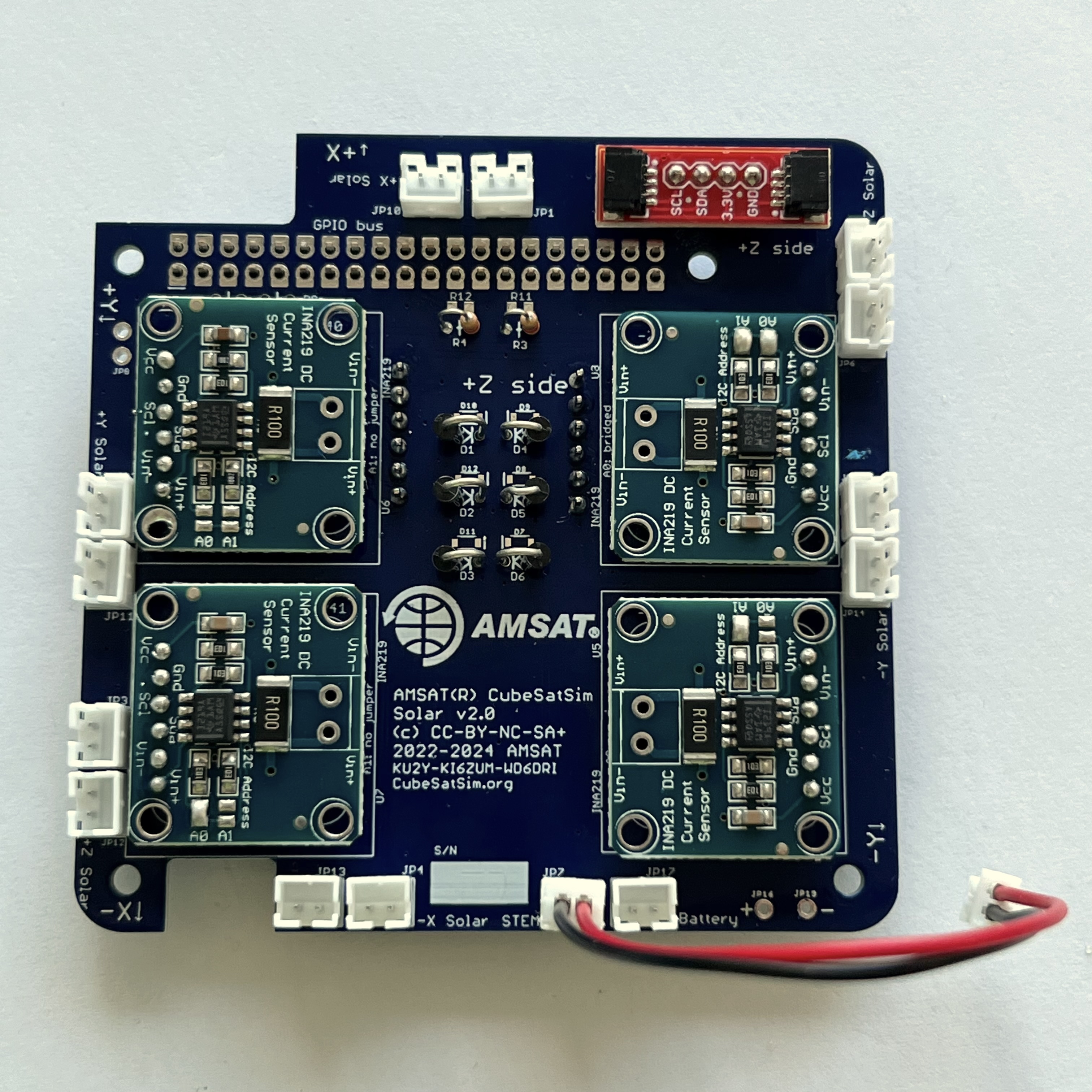
This modification is valid on the CubeSatSim v2 and v1.3.2 PCB (blue boards). Here is the Solar PCB fully assembled:
Materials

You will need:
- Solar PCB v2 or v1.3.2 outside of the frame so you can cut a trace and solder wires
- male breakaway pin headers, at least 6 pins with a total pin length of at least 15cm. For example https://www.digikey.com/en/products/detail/samtec-inc/TSW-106-22-T-S/7867293 provides 6 pins
- jumper https://www.digikey.com/en/products/detail/sullins-connector-solutions/QPC02SXGN-RC/2618262
- female to female and male to male jumper wires, at least 20cm in length (sometimes called Dupont Cables). You can buy them in sets such as: https://www.amazon.com/dp/B07GD2BWPY
Note: in place of the pin headers and jumper wires, you can just use three wires, and then twist wires together or use a small wire nut. But the pin headers and jumper wires are much easier to work with.
Tools:
- You will need soldering tools including an iron, solder wire, blue putty to hold parts, etc
- pliers or side cutters to break pin headers into individual pins
- box cutter or X-ACTO knife
Here are images of the Solar PCB. Pictured is the v2, but the v1.3.2 looks very similar:
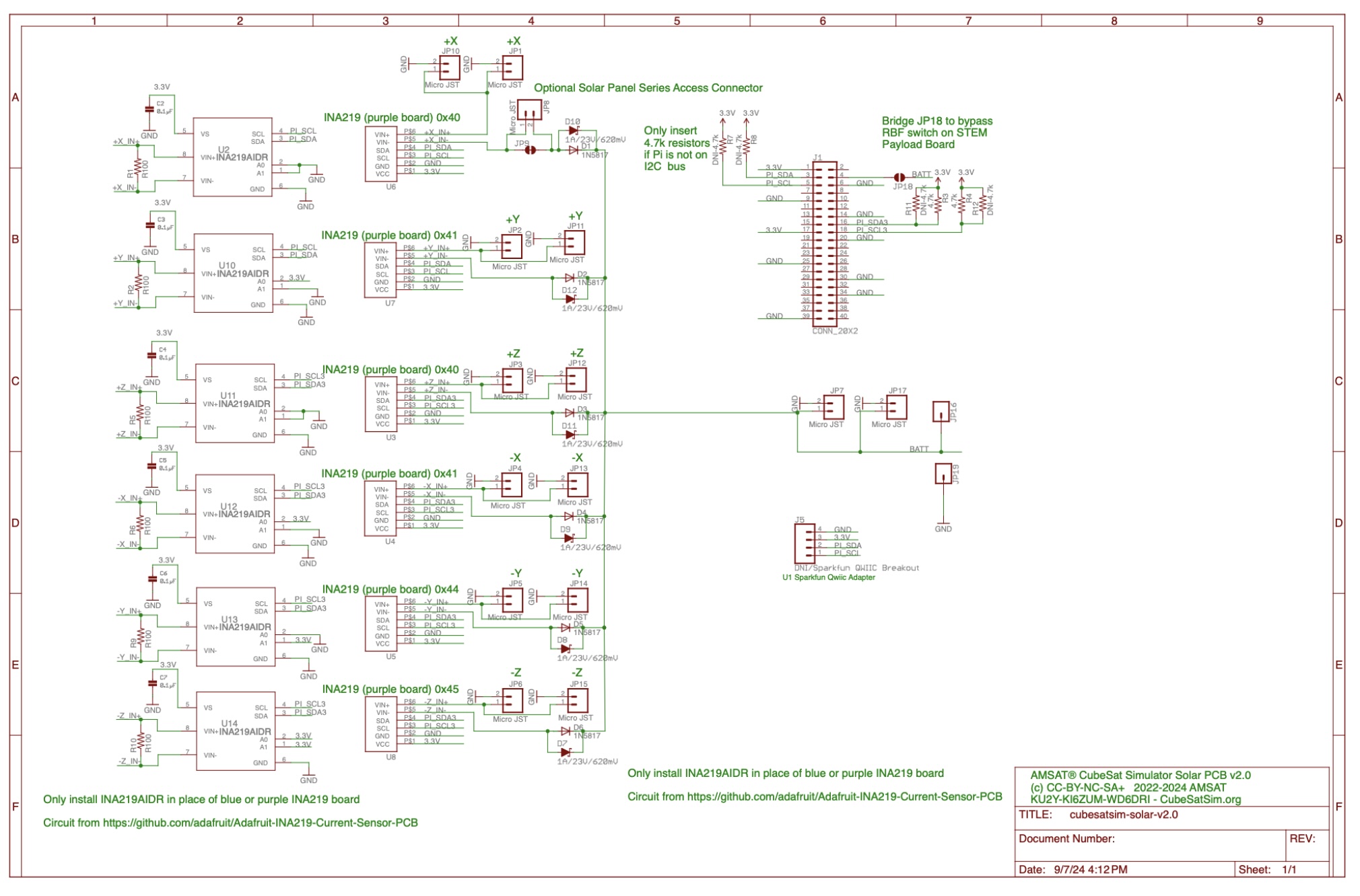
Here is the schematic:
Steps
First, find the jumper JP9 on the bottom of the Solar PCB. Here it is on the upper right side of the PCB if the GPIO header is the top.

Using the boxcutter or knife, cut the trace by making several cuts on the PCB. Angling the blade slightly can help. A close-up inspection should show that there is no longer a connection between the two nodes.

Cut or break the pin header so you have three individual pin headers. Insert two of them into JP8 on the top of the PCB:

Secure in place with blue putty to hold in place. On the PCB bottom, solder the pins. Plug the red jumper wire (Dupont cable) into the top pin of JP8, the black jumper wire into the bottom pin of JP8.

On the top of the PCB, find the JP19 pin (bottom right side if the GPIO header is on the top) and insert a pin header, short pin length down:

If you have a v1.3.2 board, there won't be a JP19, but instead look for J4 in the same place. One pin is labeled GND. Insert the pin there:

Secure the pin in place with blue putty. On the bottom of the PCB, solder the pin.
Plug the green jumper wire (Dupont cable) into the pin:

Secure all three wires together with tape, velcro, or a rubber band.

When installing the Solar Board in the frame, make sure all three wires are at the top and easily accessible without removing the frame top with tweezers or pliers.
Insert the other end of the red, black, and green jumpers into the 1x3 male pin header in this order:

Plug a jumper (red in this photos) between the red and black wires:

Here is the Solar board fully modified:

To do some other solar panel activities, when you stack the boards, it is a good idea to plug the Battery JST jumper into the Main board (the Main board will need to have JST connectors J6 and J7 installed:
TBD
Then, the Solar board will have just one JST jumper to the Main board:
TBD
Your Solar board is now ready for solar panel activities!
Solar Panel Open Circuit
To do an Open Circuit measurement on the +X Solar Panel, remove the jumper between the red and black wires:

To restore, put the jumper back between red and black.
Solar Panel Short Circuit
To do a Short Circuit measurement on the +X Solar Panel, remove the jumper between the red and black wires and place it between the red and the green wires:

To restore, put the jumper back between red and black.
Solar Panel Variable Load
To apply a variable load on the +X Solar Panel, you will need two female to female jumper wires (Dupont cables) and a 10k Ohm potentiometer:

Remove the jumper between the red and black and plug one end of the jumper wires to the red and black and wires. Connect the other ends of the jumper wires to the center and outer pins of the 10k trim pot:

To restore, put the jumper back between red and black.