Pico v0.2 SMD Instructions - alanbjohnston/CubeSatSim GitHub Wiki
Building the CubeSatSim Pico SMD
These are the instructions for building the Pico Board and Solar Board as Surface Mount Device (SMD) Boards
Here is the software for the CubeSatSim Pico: https://github.com/alanbjohnston/CubeSatSim/tree/pico/cubesatsim
Pico Board v0.2
These are the instructions for building the Pico v0.2 board SMD Components.
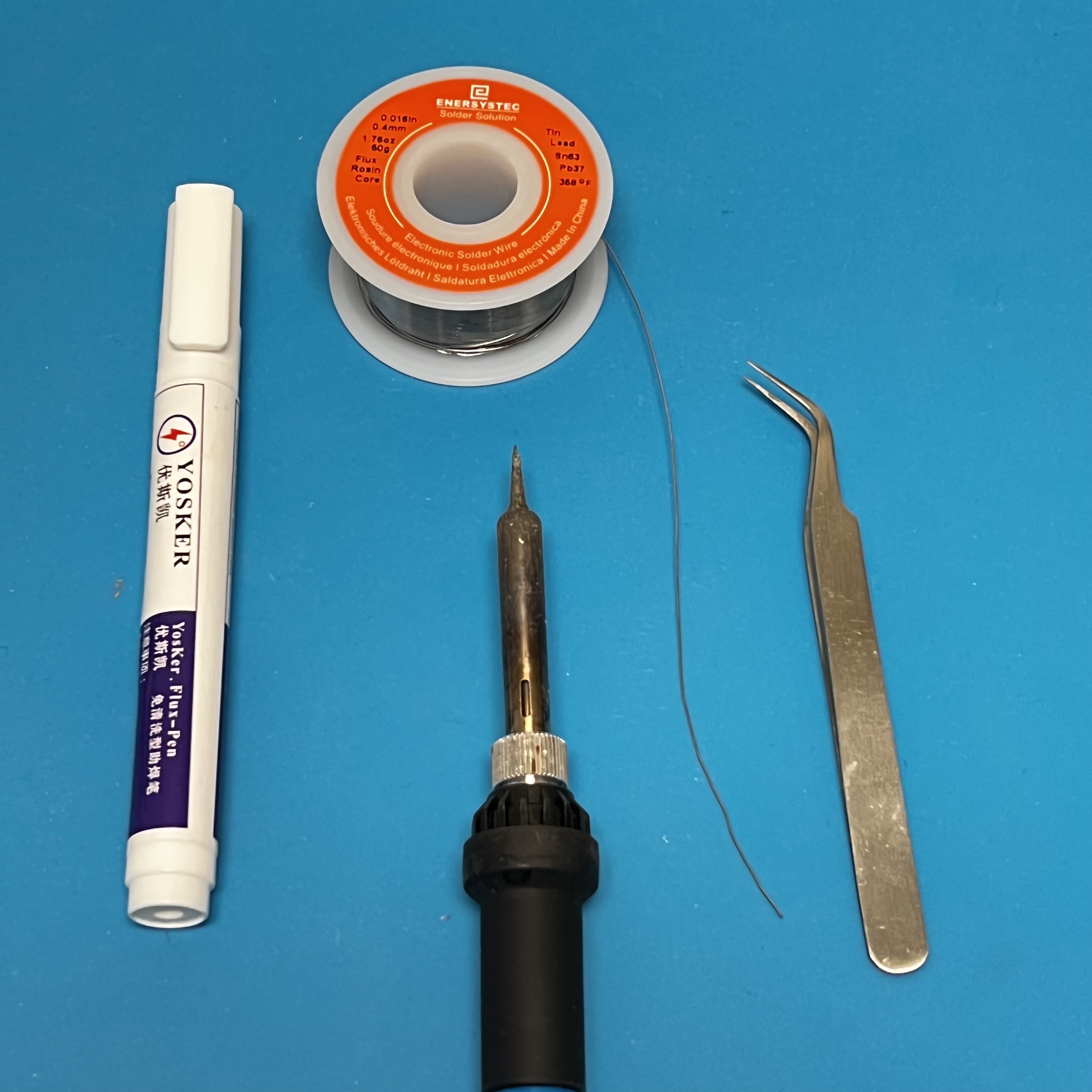
You will need these tools:
- Safety glasses (to protect eyes while soldering or trimming leads)
- Soldering iron with fine tip and very thin solder (I use lead-free solder, but leaded solder is easier to work with)
- Flux pen
- Tweezers
- Needle nose pliers (to bend leads and hold parts)
Assembly
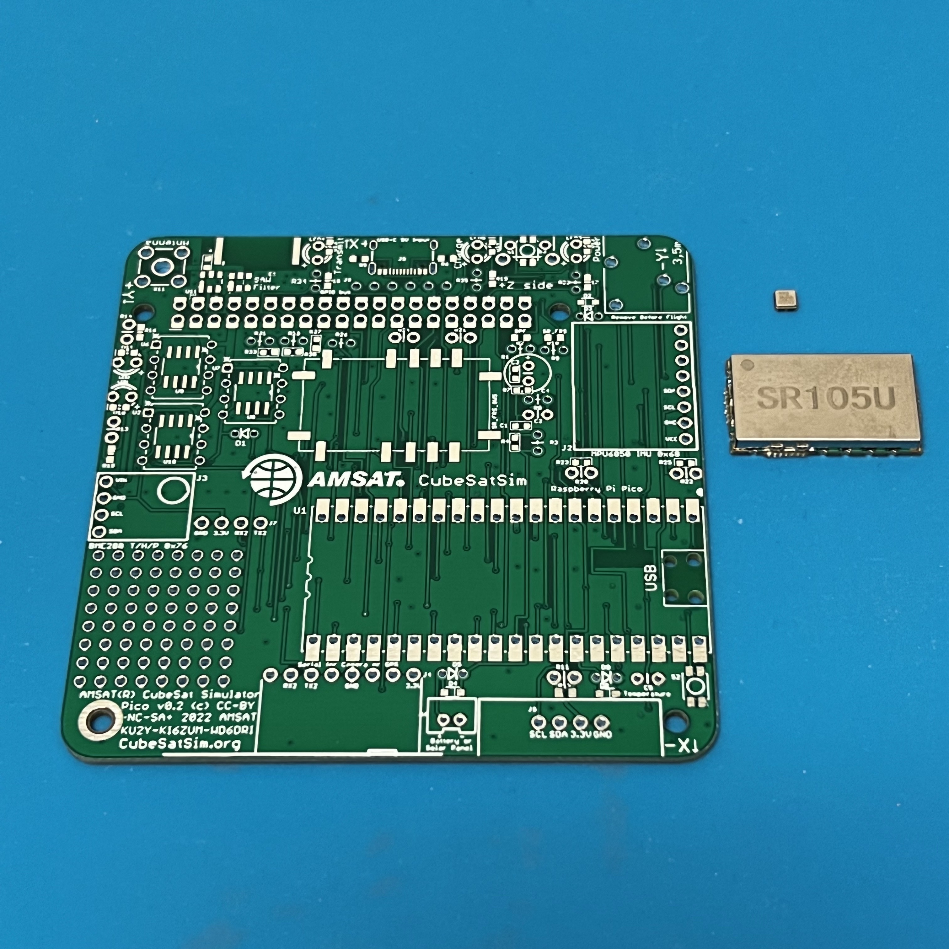
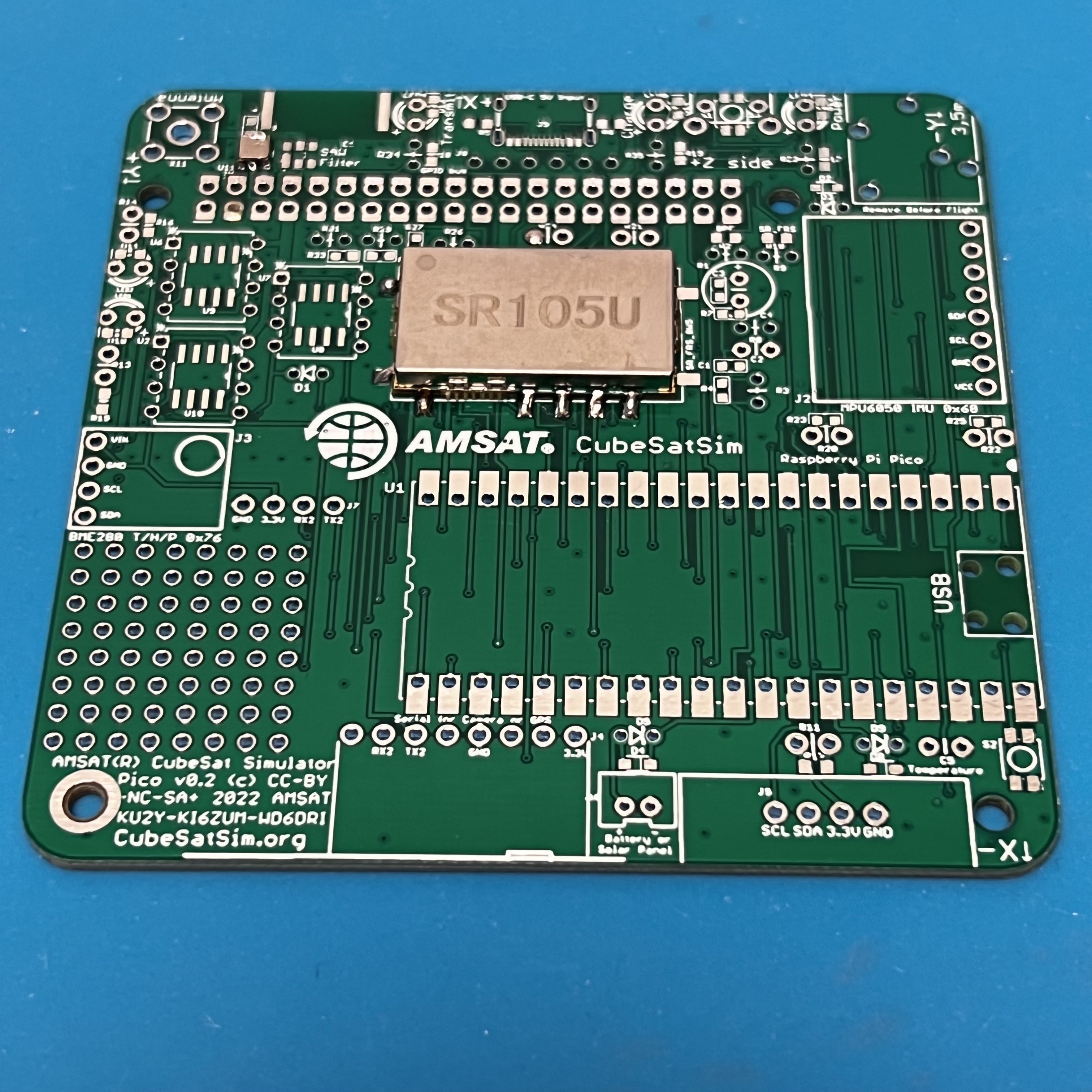
Here is the Pico v0.4 PCB:


Here is the schematic:
First solder the surface mount parts. If the SAW filter, SR_FRS transmitter, USB-C, and clockgen components are already mounted, you can skip to the Through Hole Parts section.

SMD Parts
To do the SMD soldering, you will need these tools:
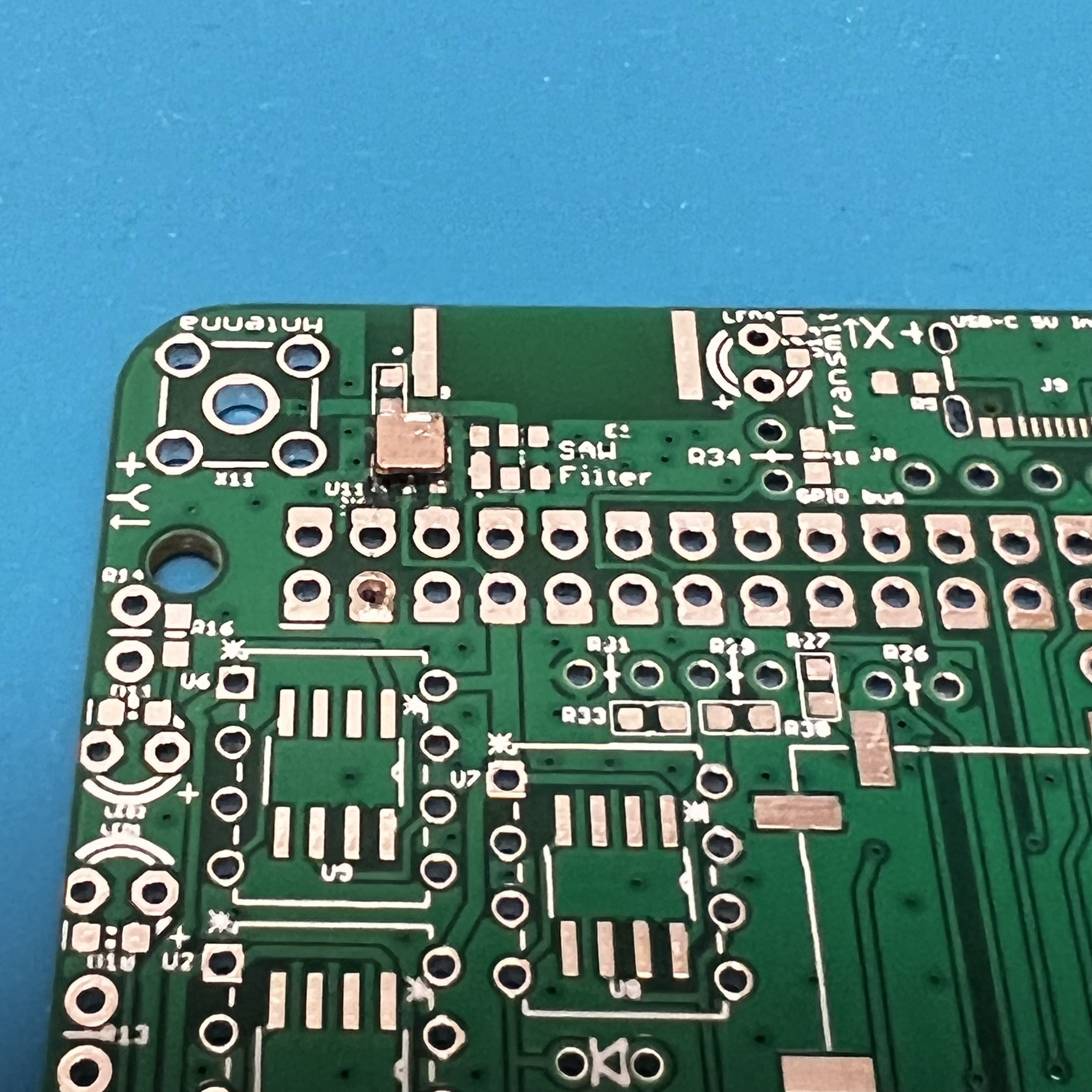
Start with the SAW Filter U7 and the SR_FRS board U6.
Apply liquid flux to the footprint,
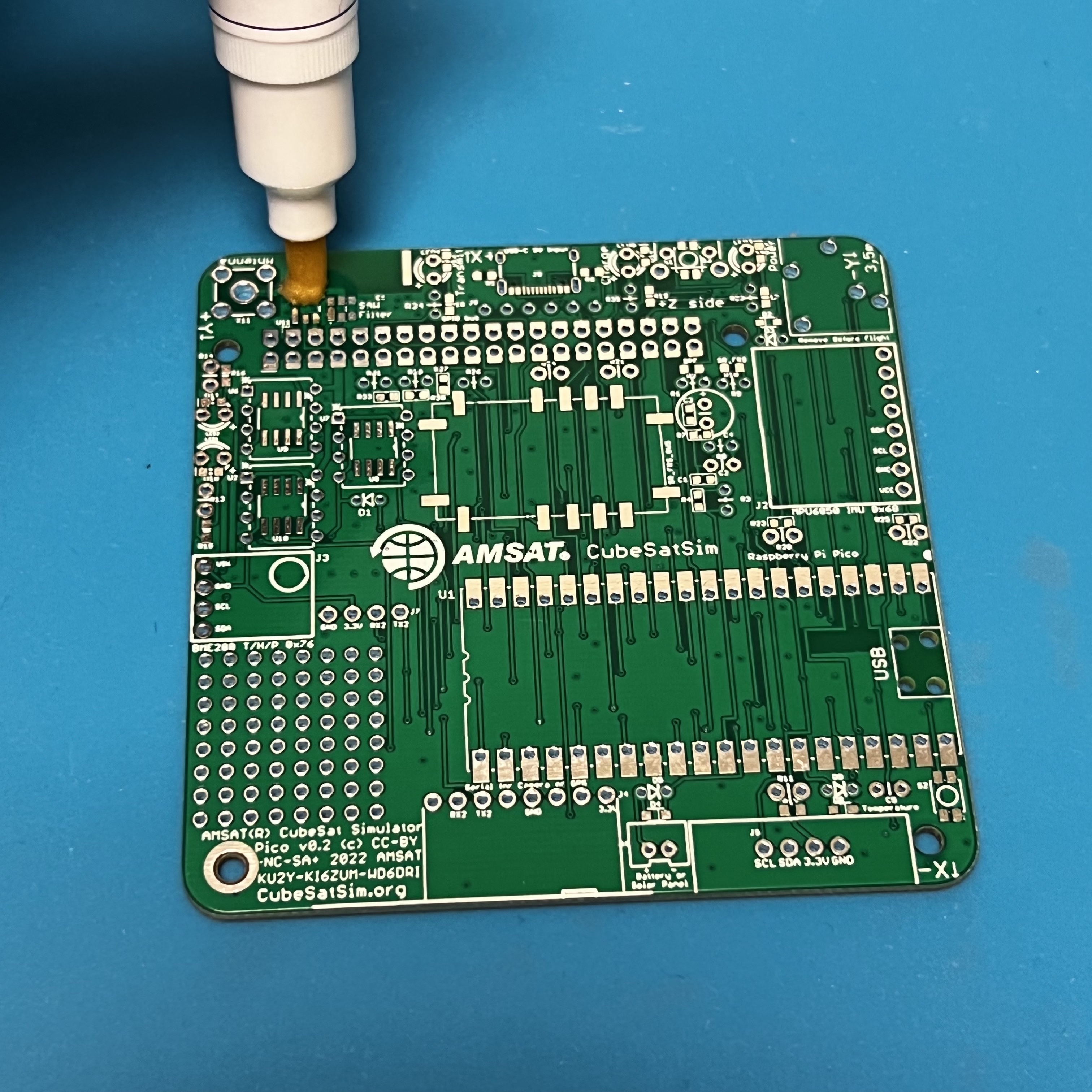
then place the SAW filter with tweezers.
While soldering the first pin, hold the part in place by pressing down with the tweezers. Once one pin is soldered, the part should stay in place as you solder the remaining parts. Be careful not to apply too much solder. If there are any bridges, apply lots of liquid flux then drag the soldering iron across the pins and the bridge should go away.
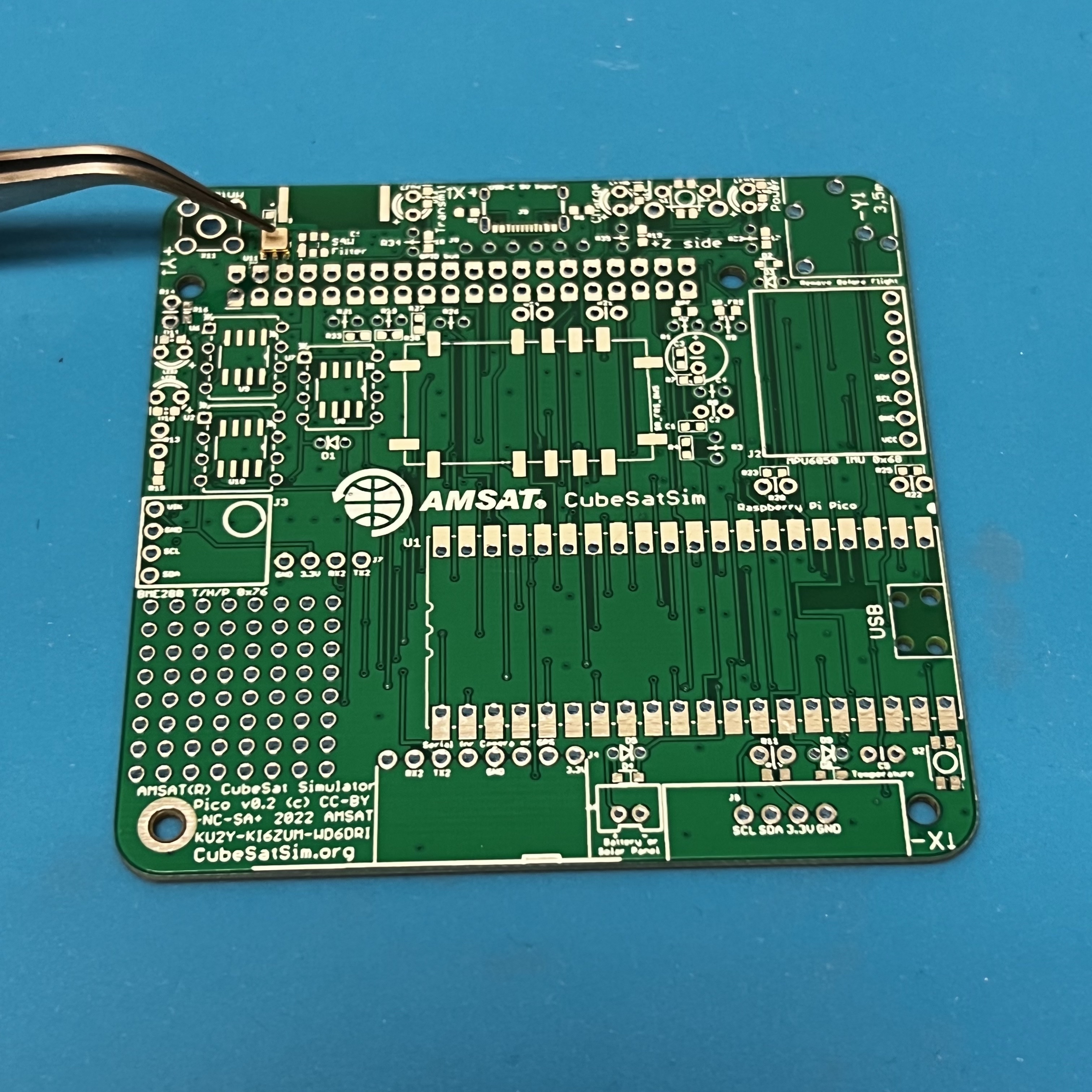
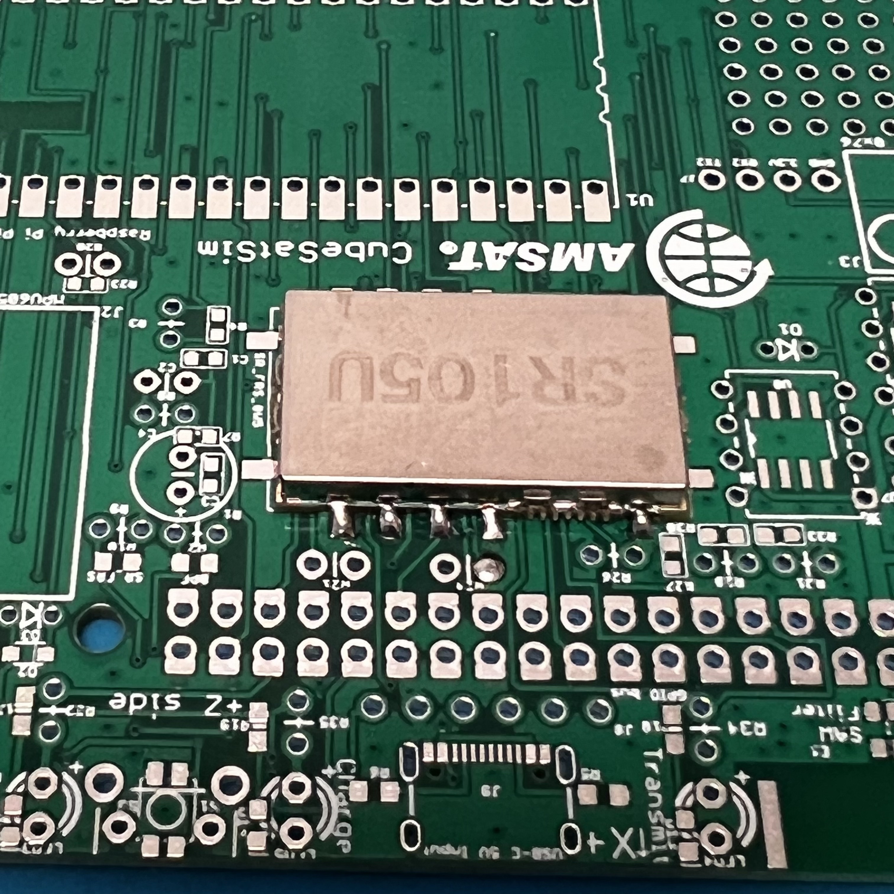
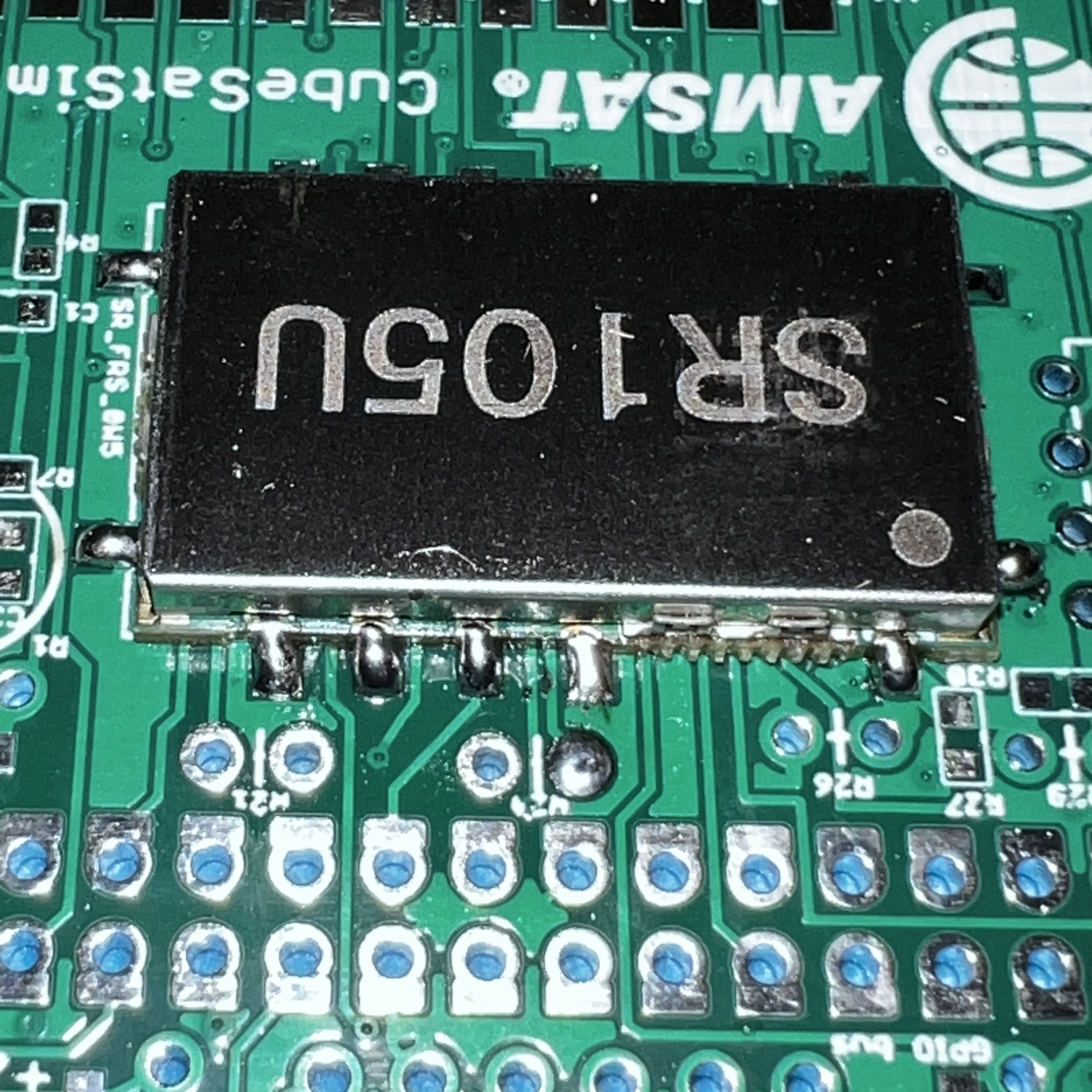
Next solder the SR_FRS board.
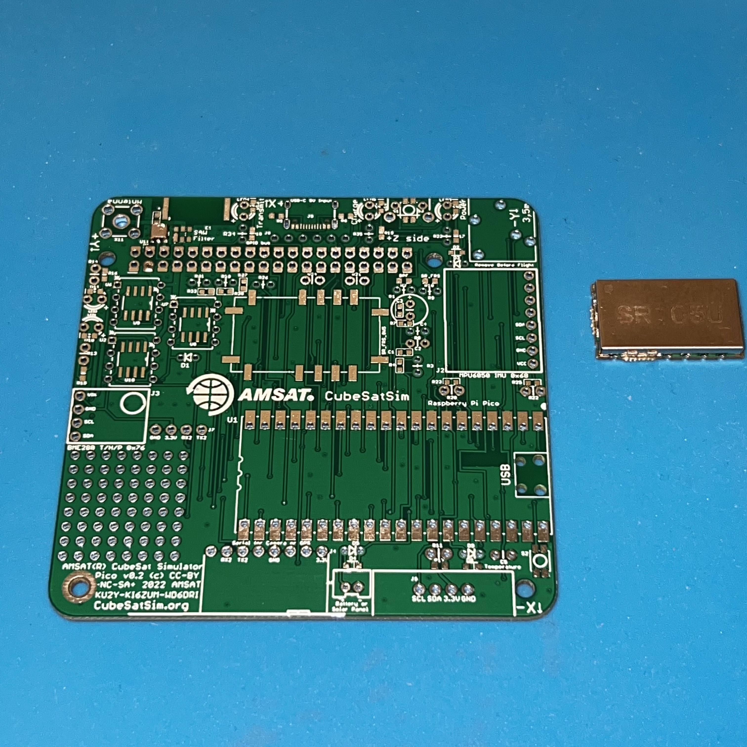
Apply plenty of liquid flux to all pins, then place the part on the pads. Again, solder one pin while holding down the part with the tweezers. Here, I solder the pin on the lower left.
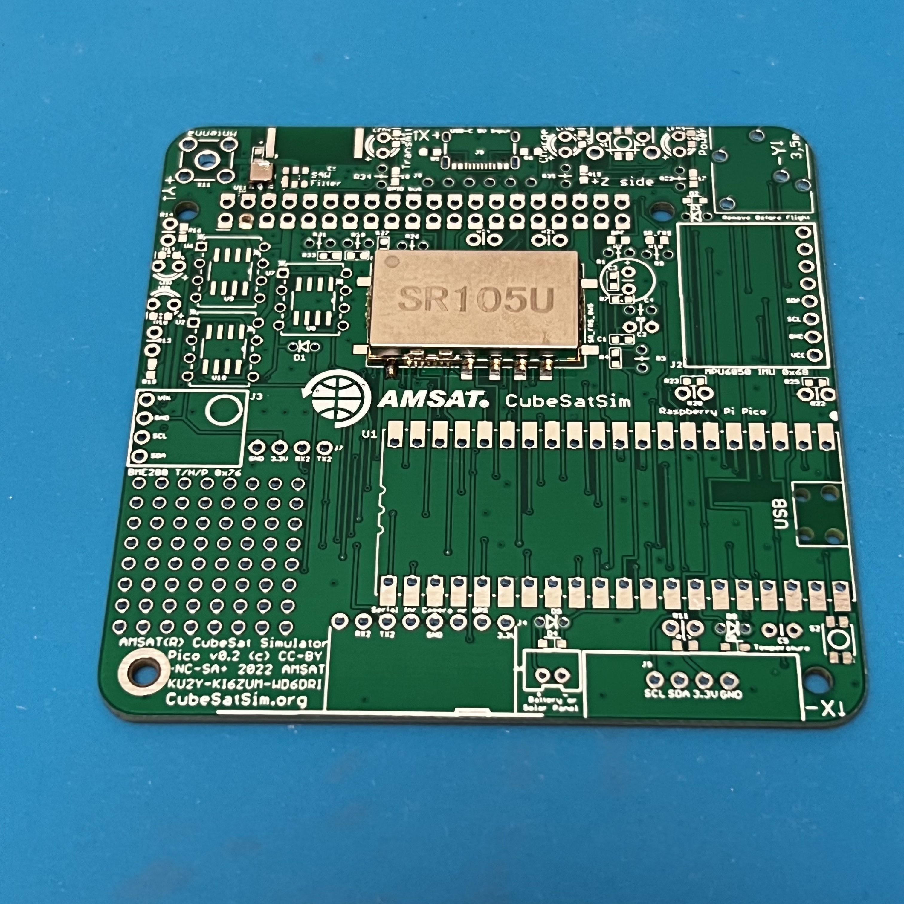
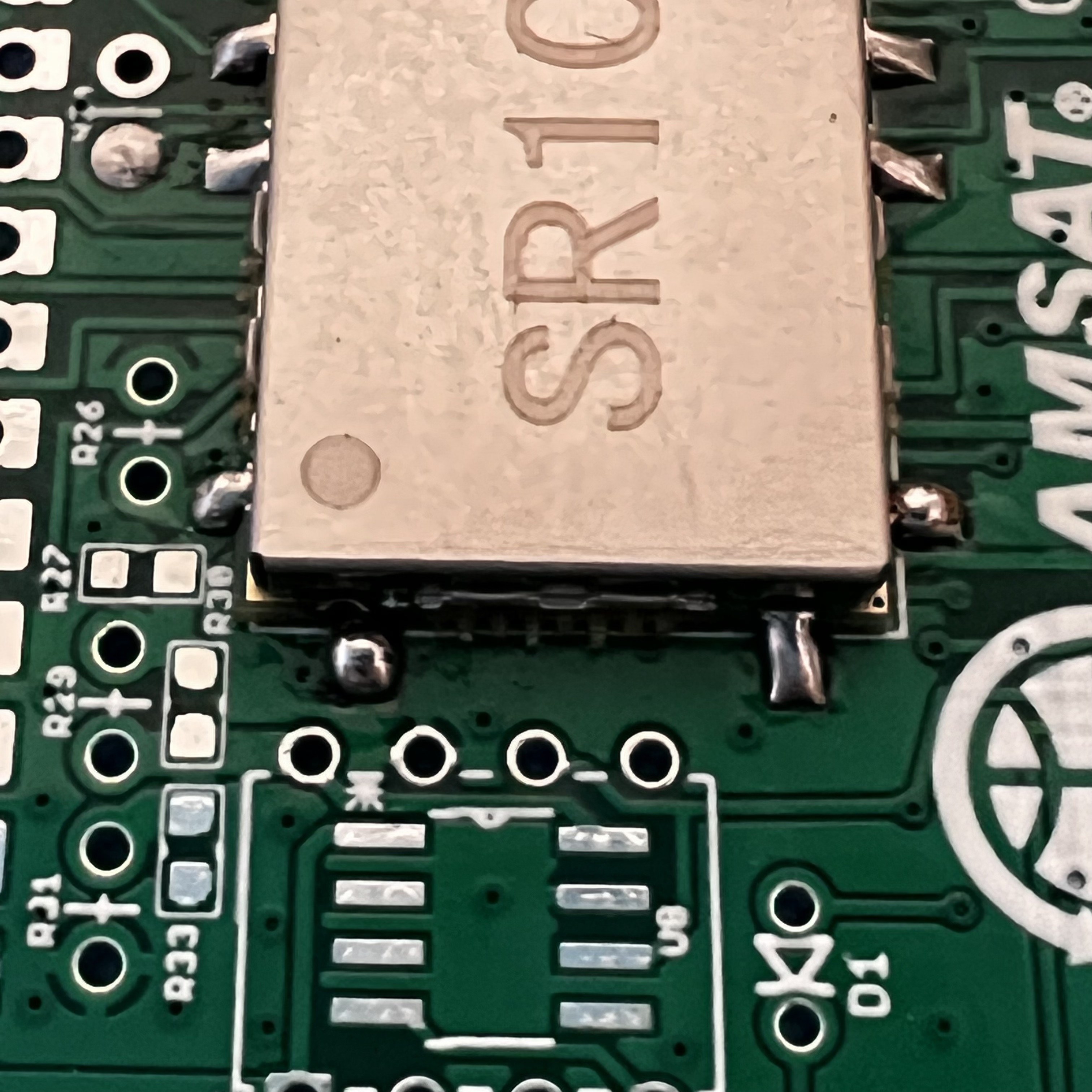
Then, solder one pin on the other side of the part, in this case the lower left pin. You may need to apply more liquid flux. Keep applying soldering until the whole pad is filled and the solder is a nice triangle that bridges the pin and the pad.
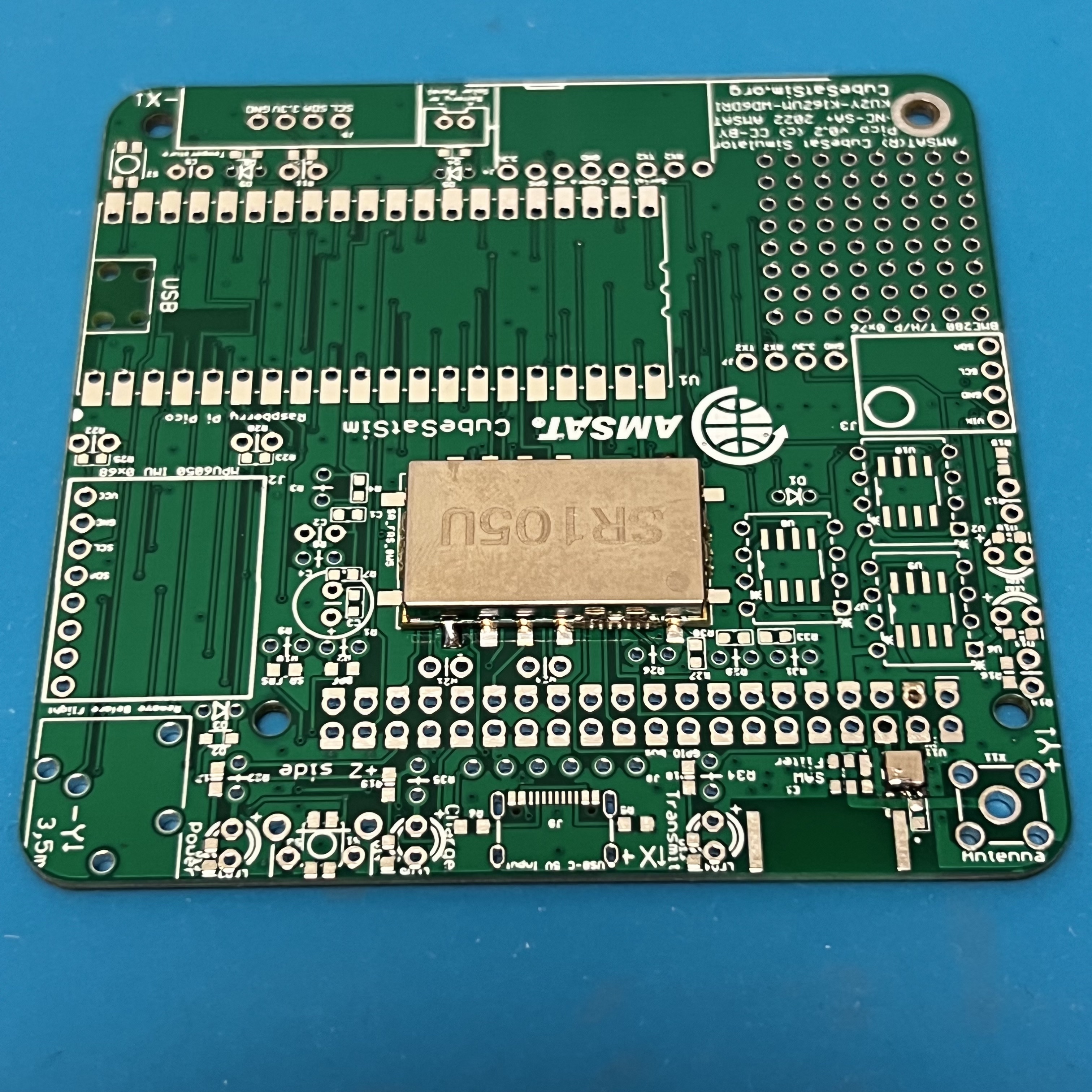
Continue soldering the rest of the pins.
This image shows a good solder joint on the right and a bad one on the left. On the right see the triangular shape that covers the pad and connects to the pin. On the left, the solder is in a ball and does not make good contact with the pin. Apply lots of liquid flux and reheat, making sure the pin gets heat.
Now, both pins are fixed.
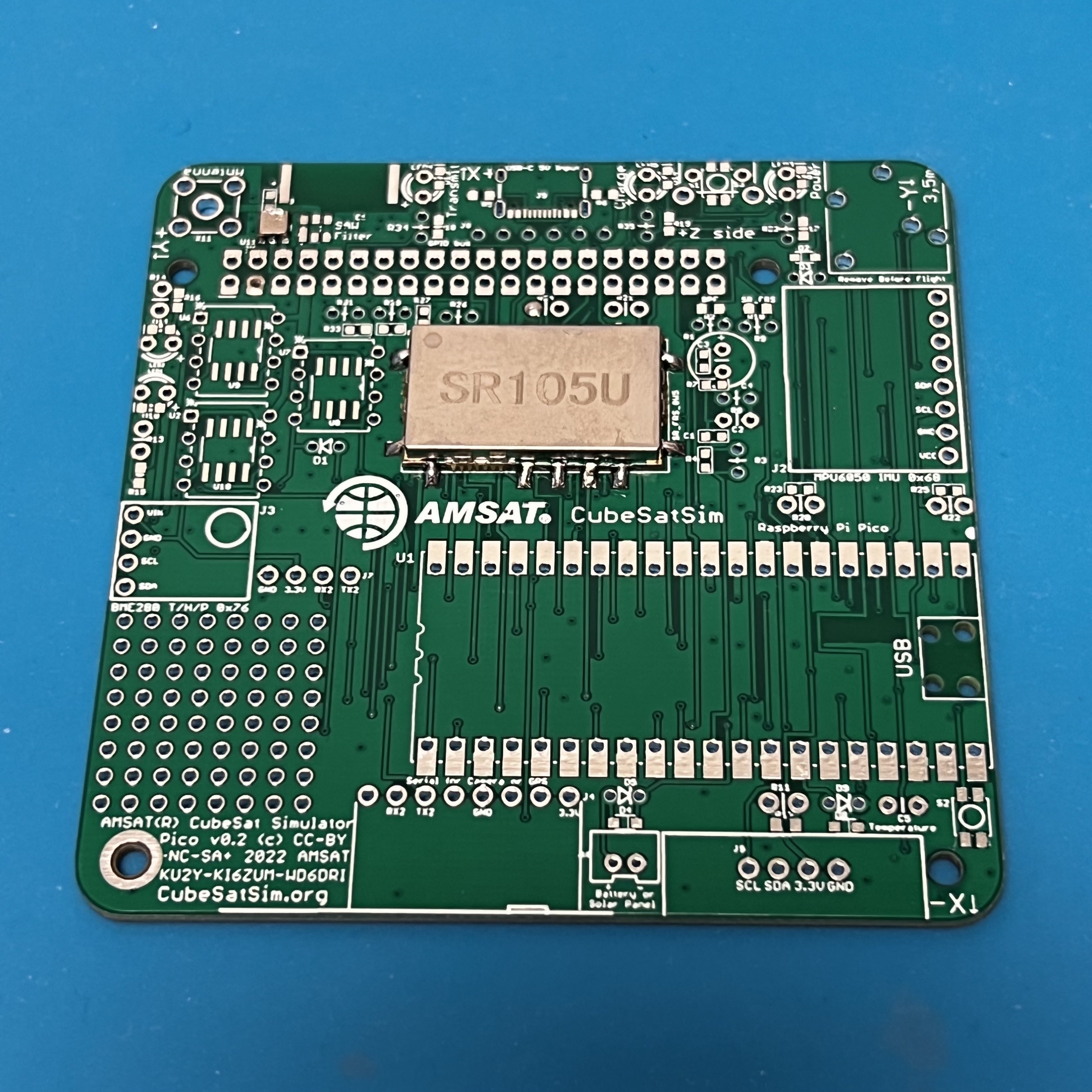
A closeup.
Finally, solder the SMD components USB-C connector J9, clockgen IC U10, crystal Y1, and capacitor C6 (no photo shown).