Pico v0.2 Board - alanbjohnston/CubeSatSim GitHub Wiki
Building the Pico v0.2 Board
These are the instructions for building the STEM Payload board.
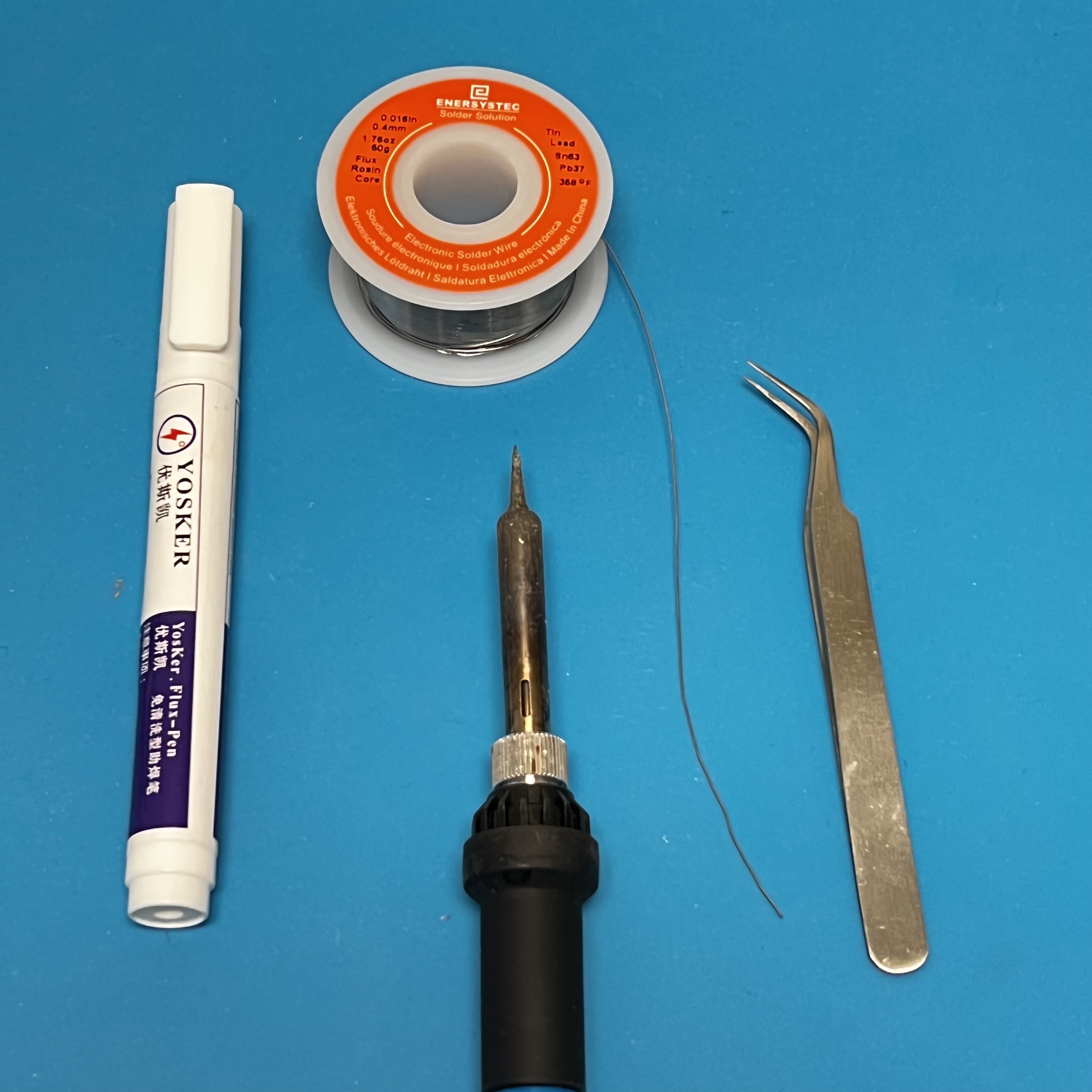
You will need these tools:
- Safety glasses (to protect eyes while soldering or trimming leads)
- Soldering iron with fine tip and very thin solder (I use lead-free solder, but leaded solder is easier to work with)
- Flux pen
- Tweezers
- Needle nose pliers (to bend leads and hold parts)
- Side cutters (to trim leads)
Other tools that are helpful:
- Blue mounting putty (to hold components in place while soldering)
Checklist
The BOM has a sheet "By Steps" which lists the parts needed for each step in order. http://cubesatsim.org/bom If you have a Google account, you can make a copy of this spreadsheet ("File" then "Make a Copy") and check off each part as you install it.
For example, here is the checklist for this step:
Assembly
Video
Here is a video of the assembly part of this step:
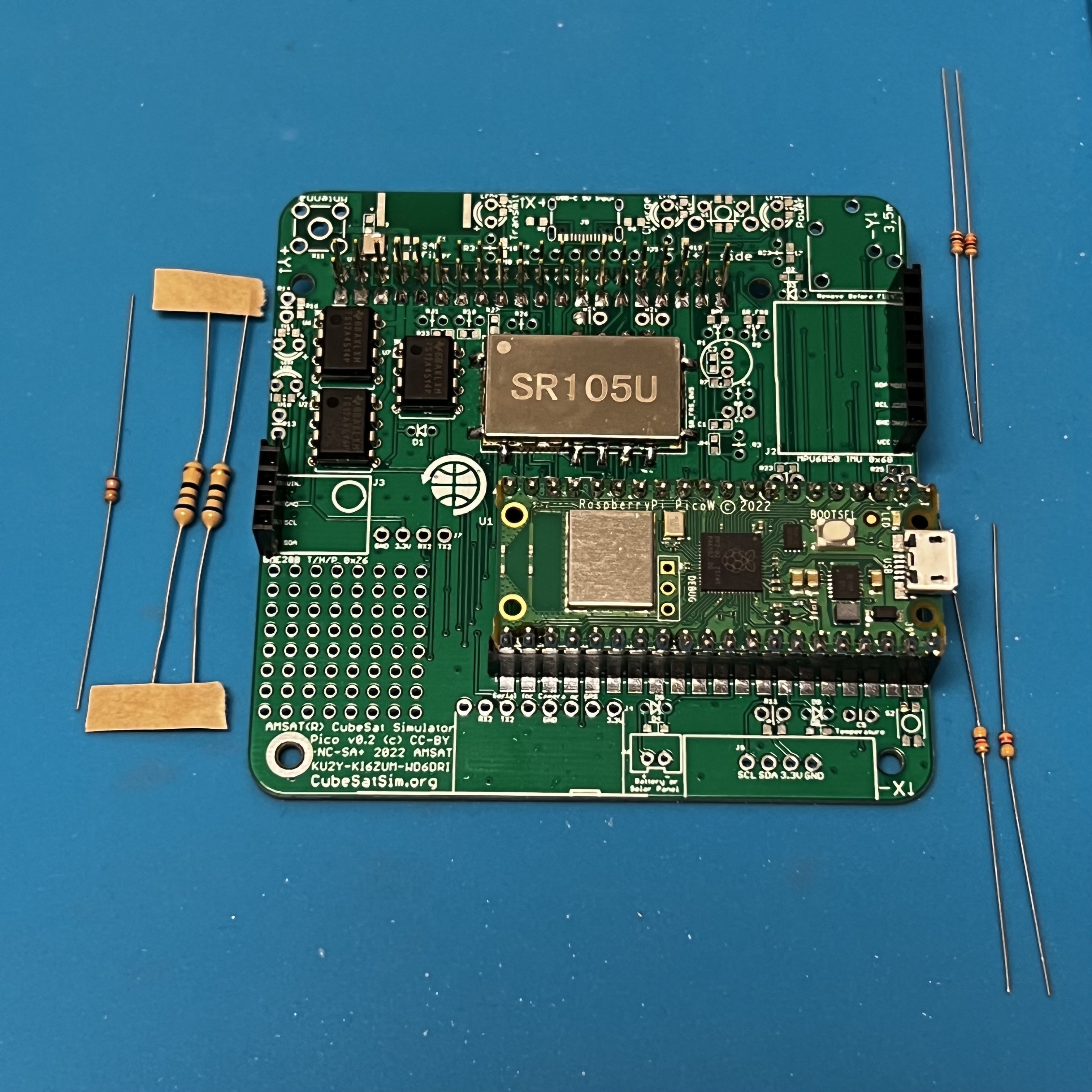
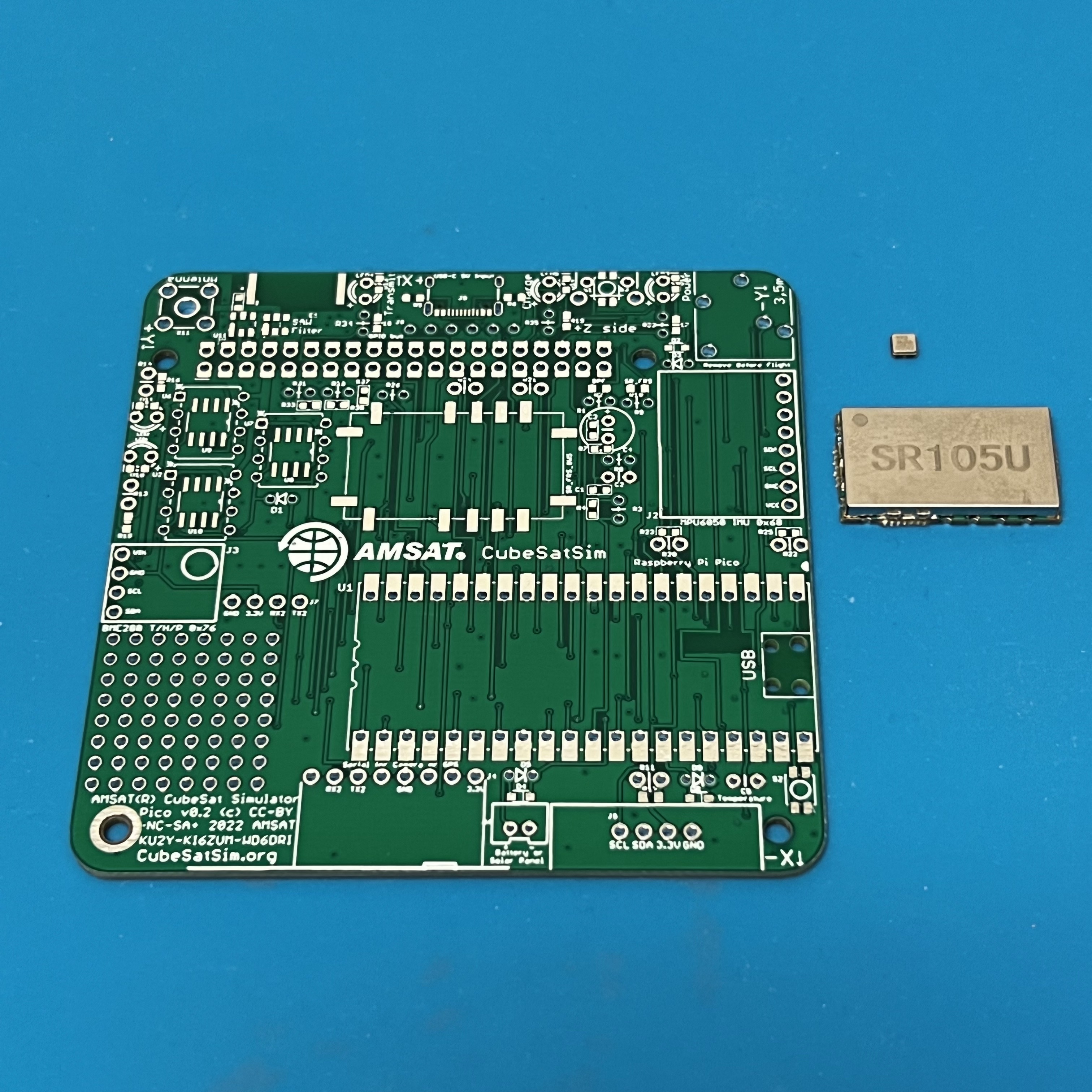
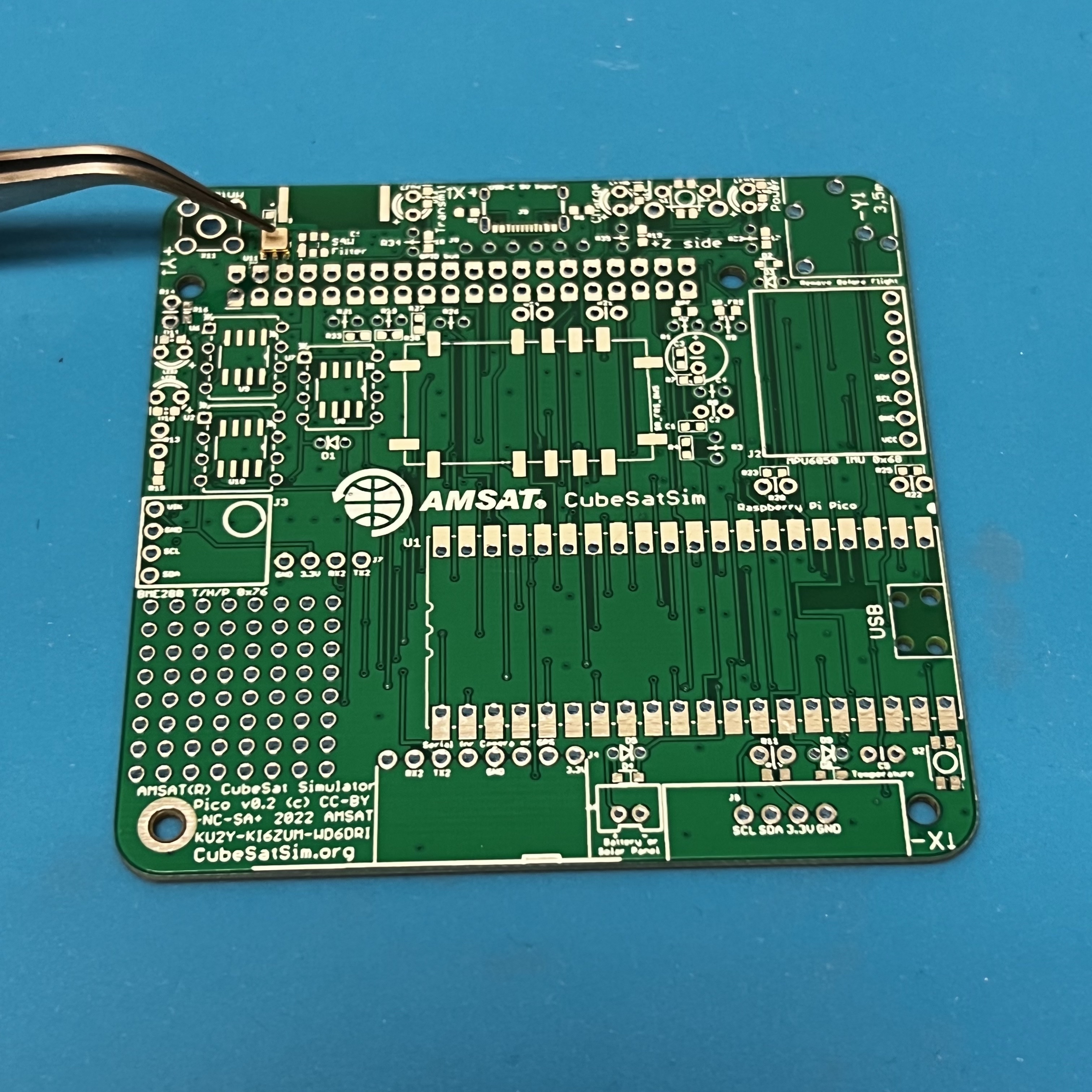
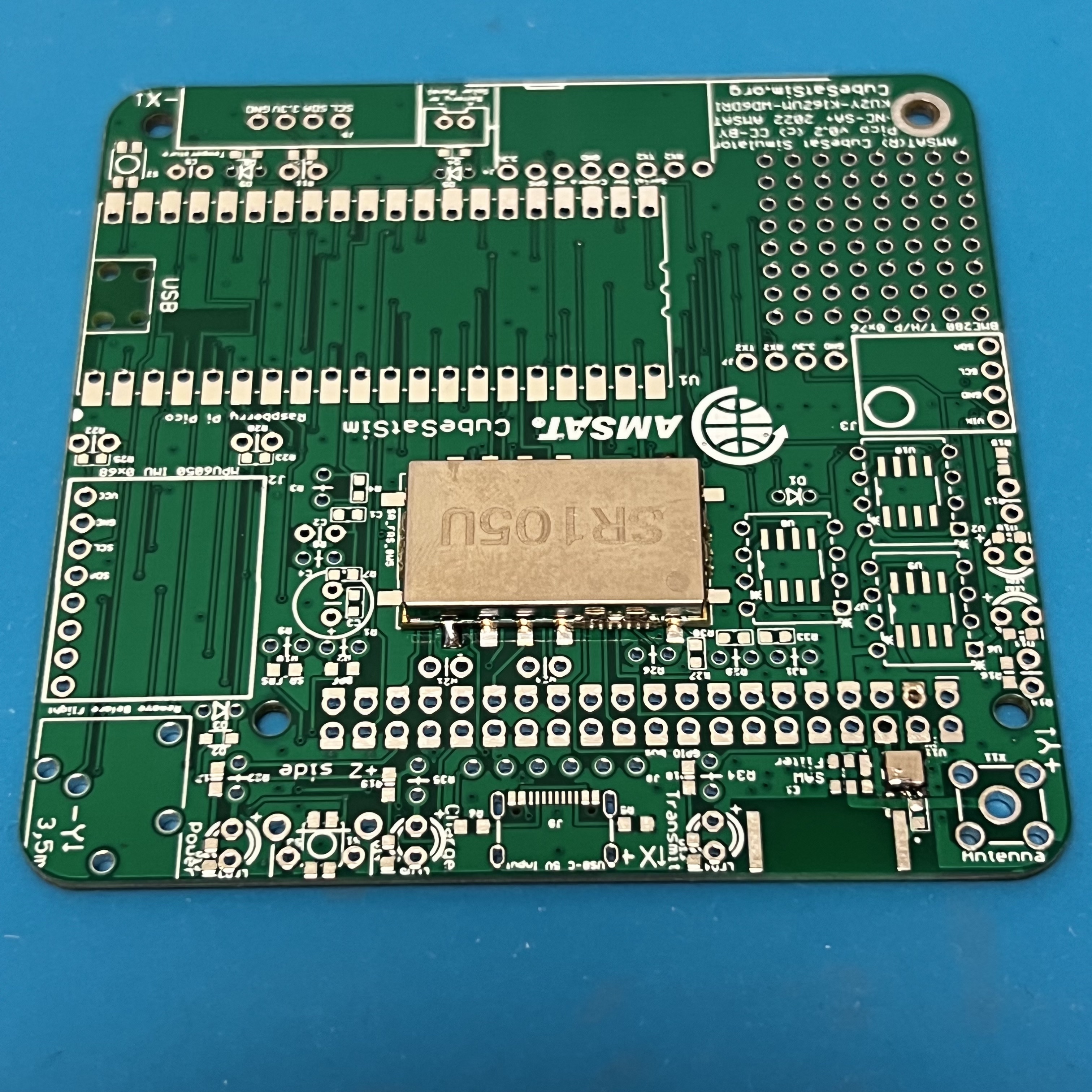
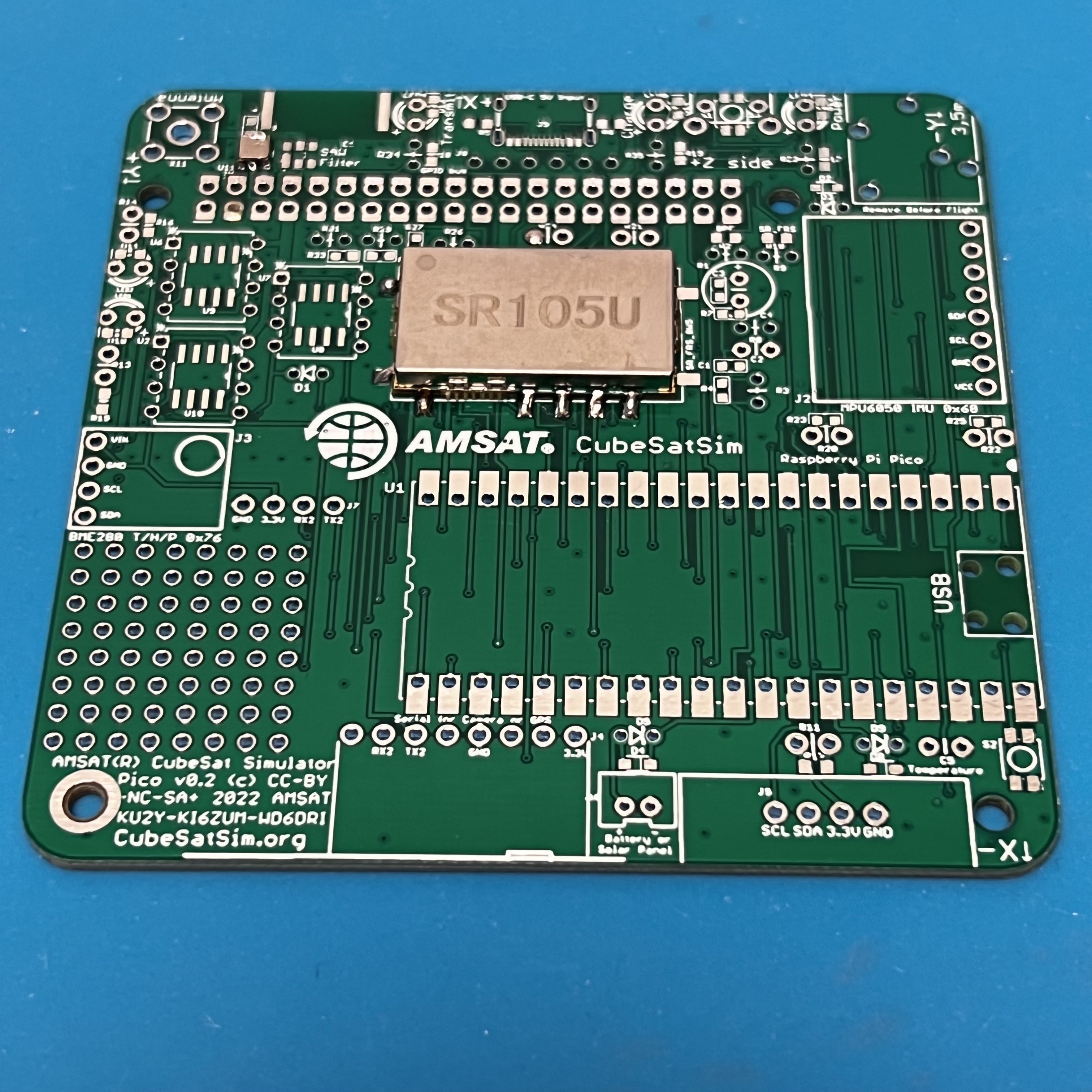
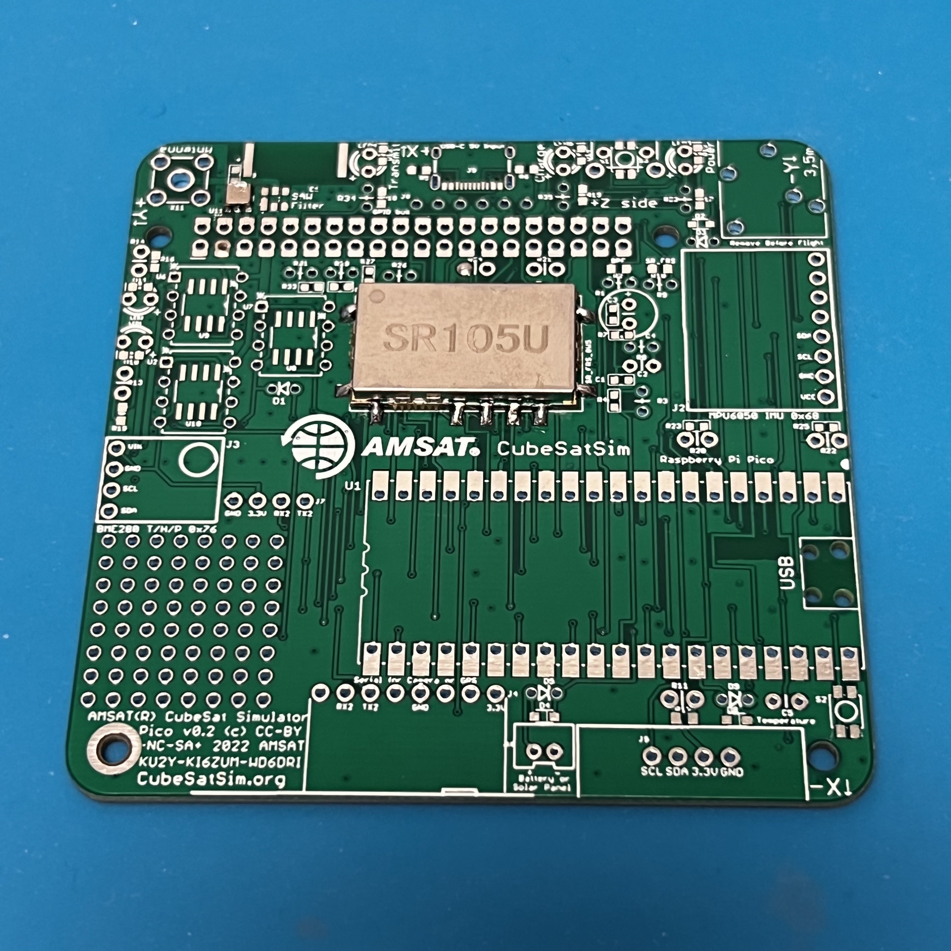
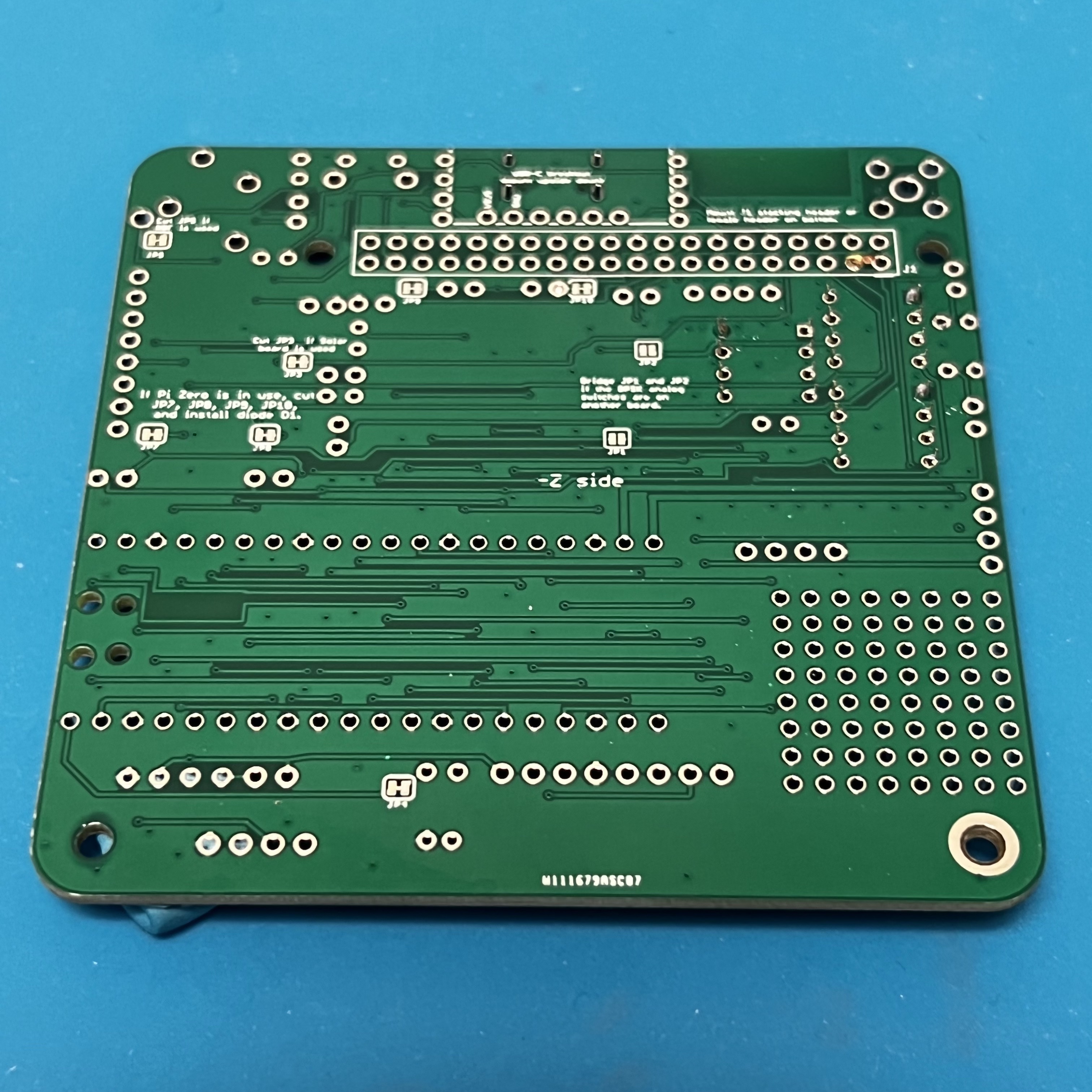
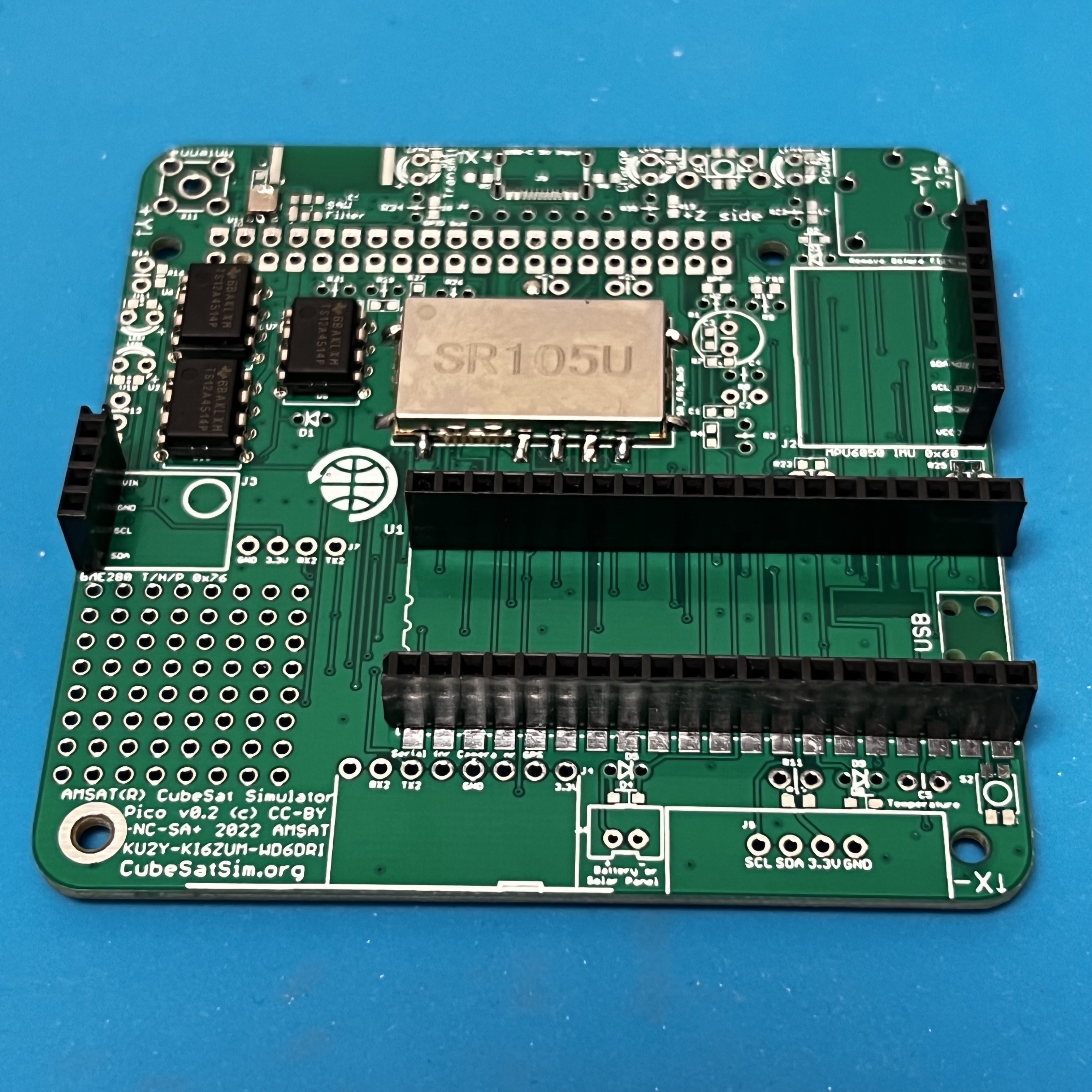
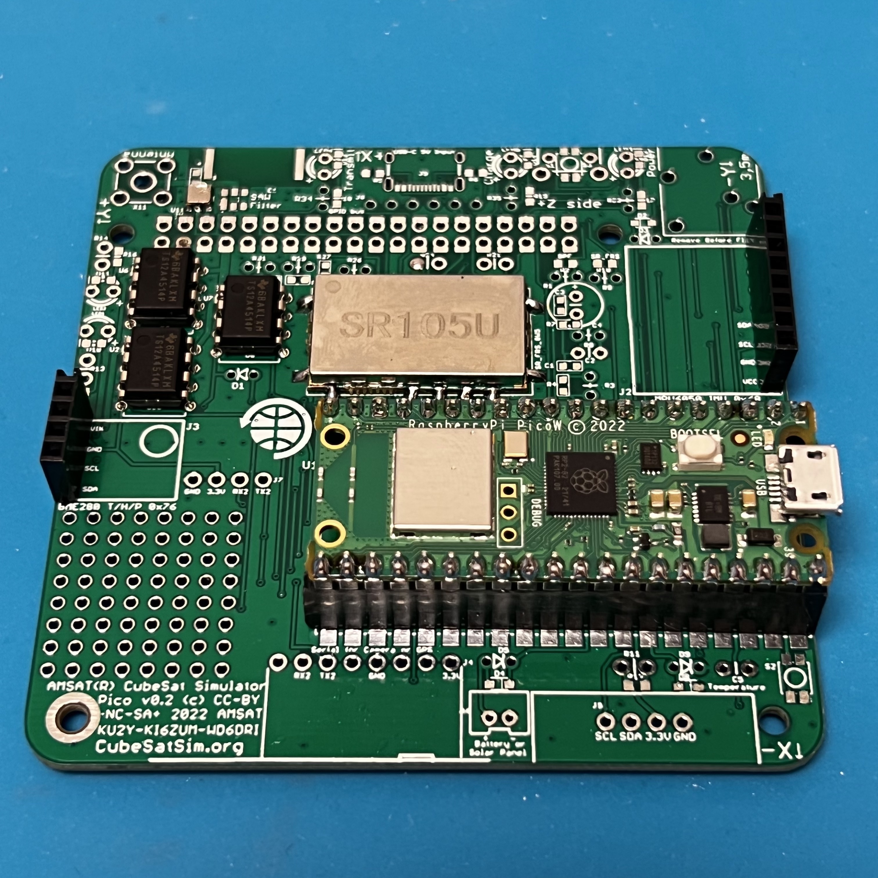
Here is the Pico v0.2 PCB:
First solder the surface mount parts. You will need these tools:
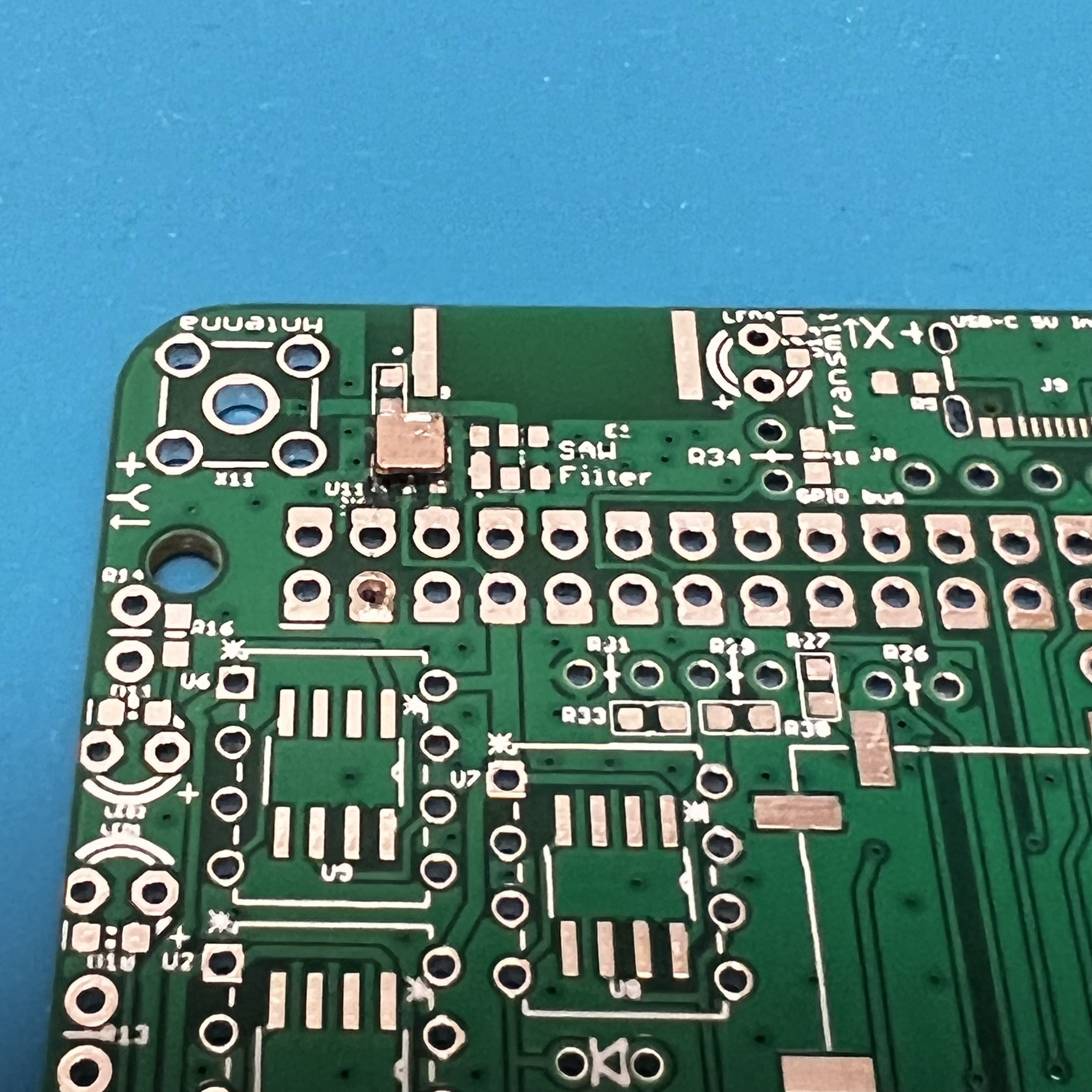
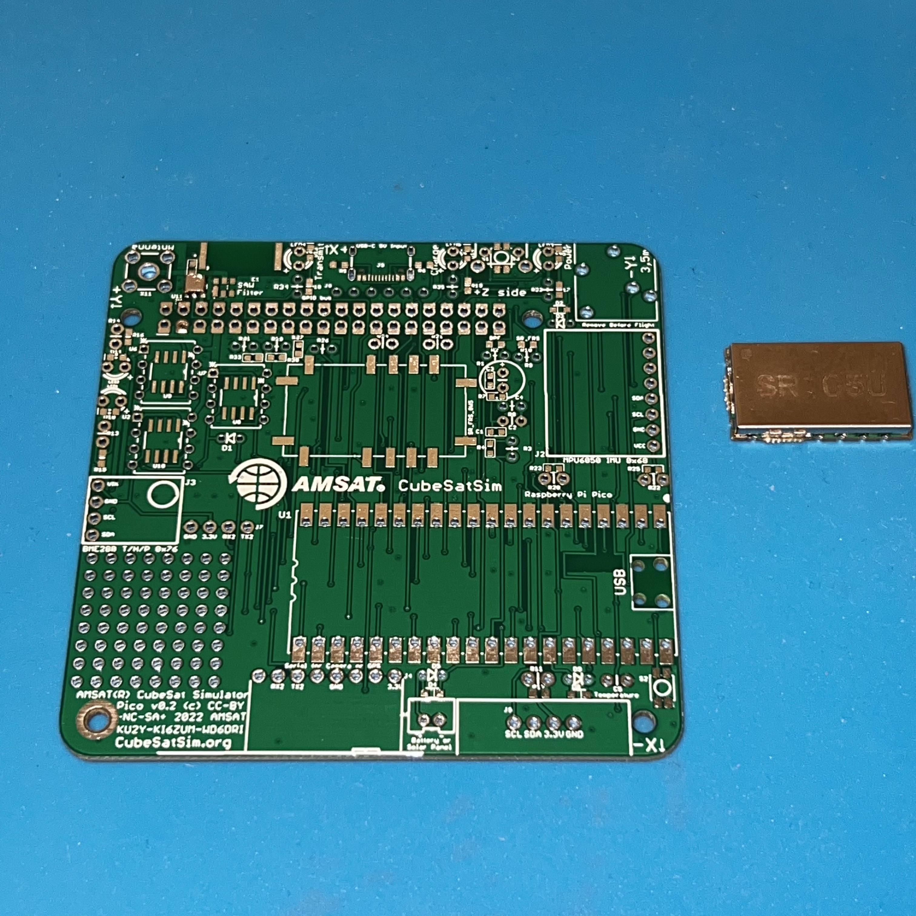
Start with the SAW Filter and the SR_FRS board.
Apply liquid flux to the footprint,
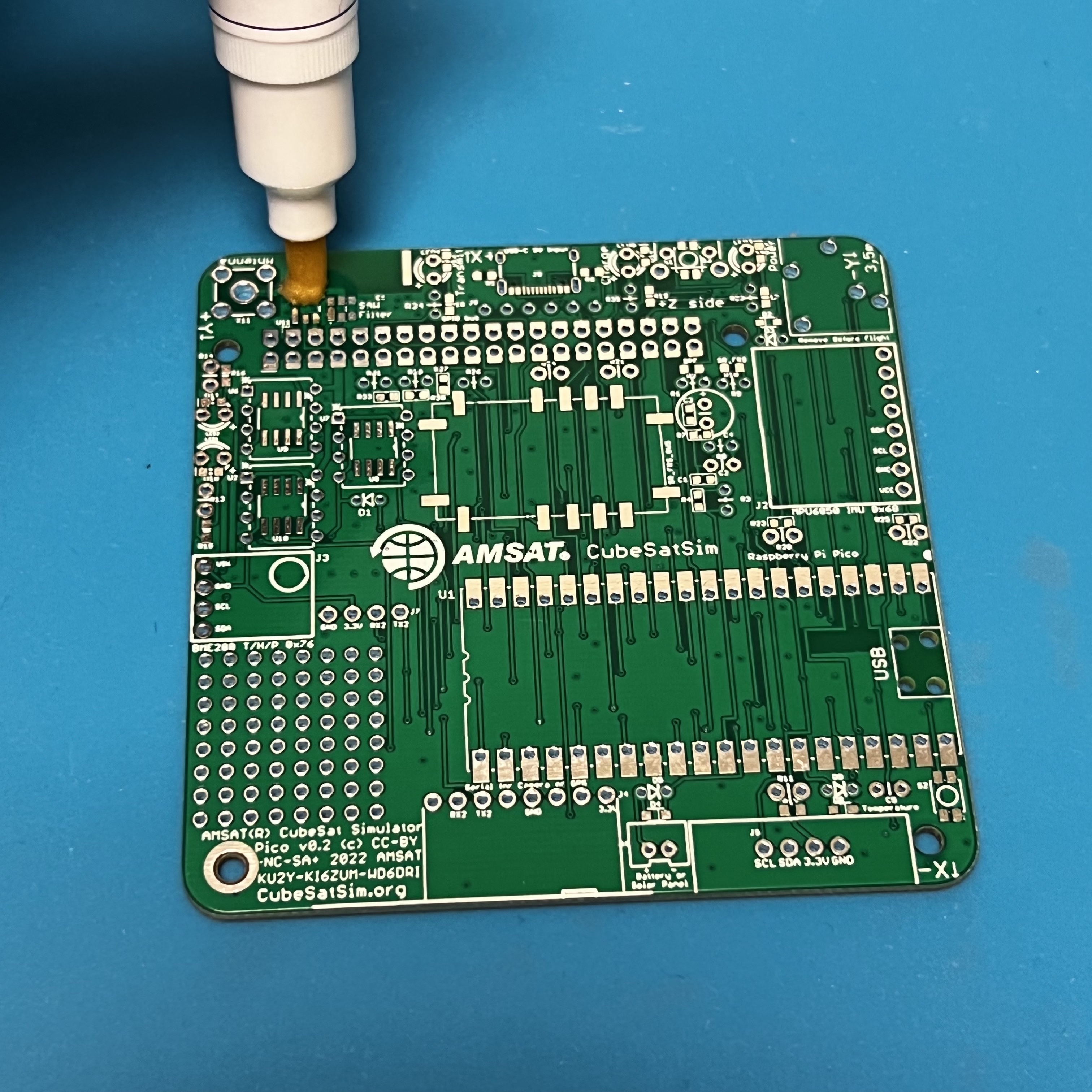
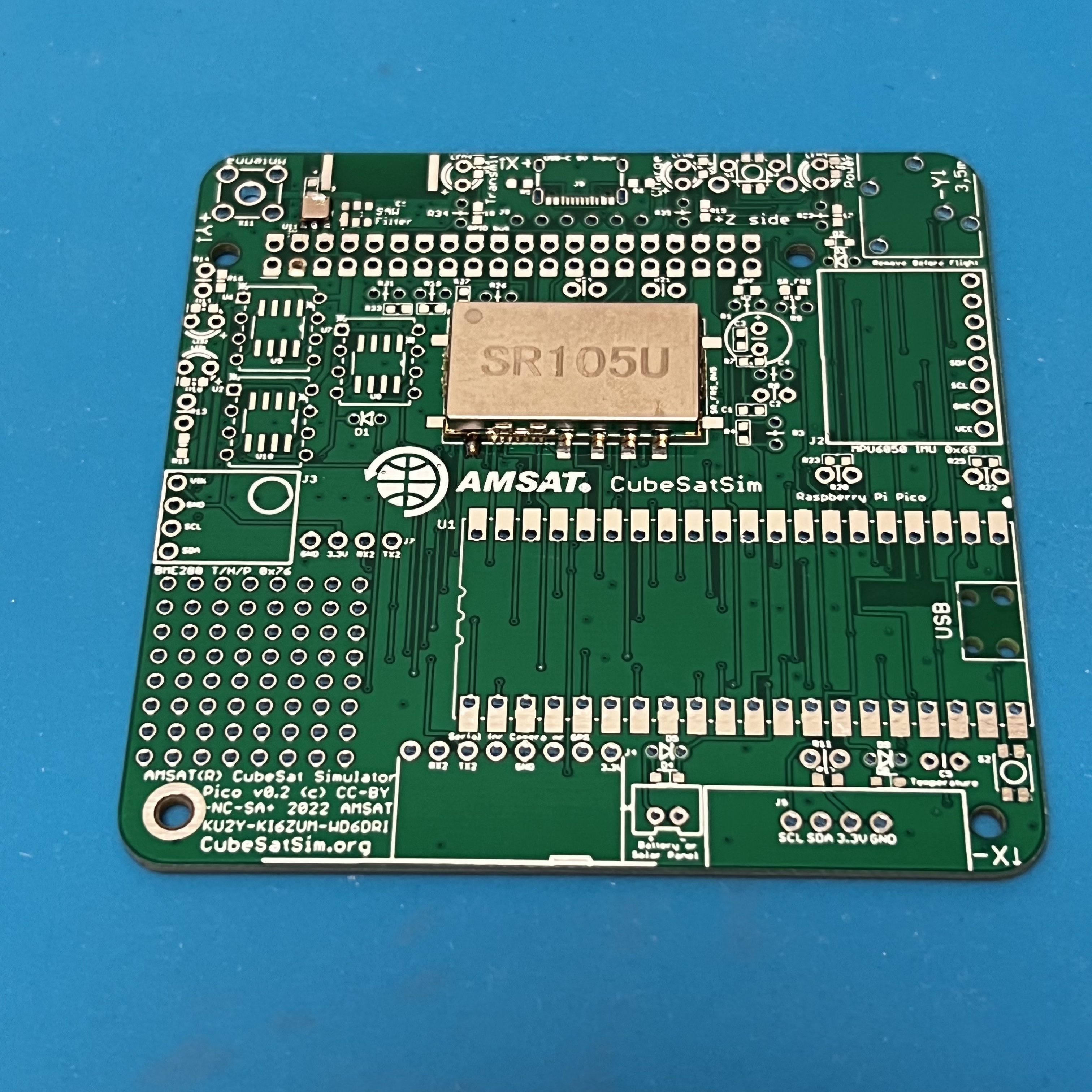
then place the SAW filter with tweezers.
While soldering the first pin, hold the part in place by pressing down with the tweezers. Once one pin is soldered, the part should stay in place as you solder the remaining parts. Be careful not to apply too much solder. If there are any bridges, apply lots of liquid flux then drag the soldering iron across the pins and the bridge should go away.
Next solder the SR_FRS board.
Apply plenty of liquid flux to all pins, then place the part on the pads. Again, solder one pin while holding down the part with the tweezers. Here, I solder the pin on the lower left.
Then, solder one pin on the other side of the part, in this case the lower left pin. You may need to apply more liquid flux. Keep applying soldering until the whole pad is filled and the solder is a nice triangle that bridges the pin and the pad.
Continue soldering the rest of the pins.
This image shows a good solder joint on the right and a bad one on the left. On the right see the triangular shape that covers the pad and connects to the pin. On the left, the solder is in a ball and does not make good contact with the pin. Apply lots of liquid flux and reheat, making sure the pin gets heat.
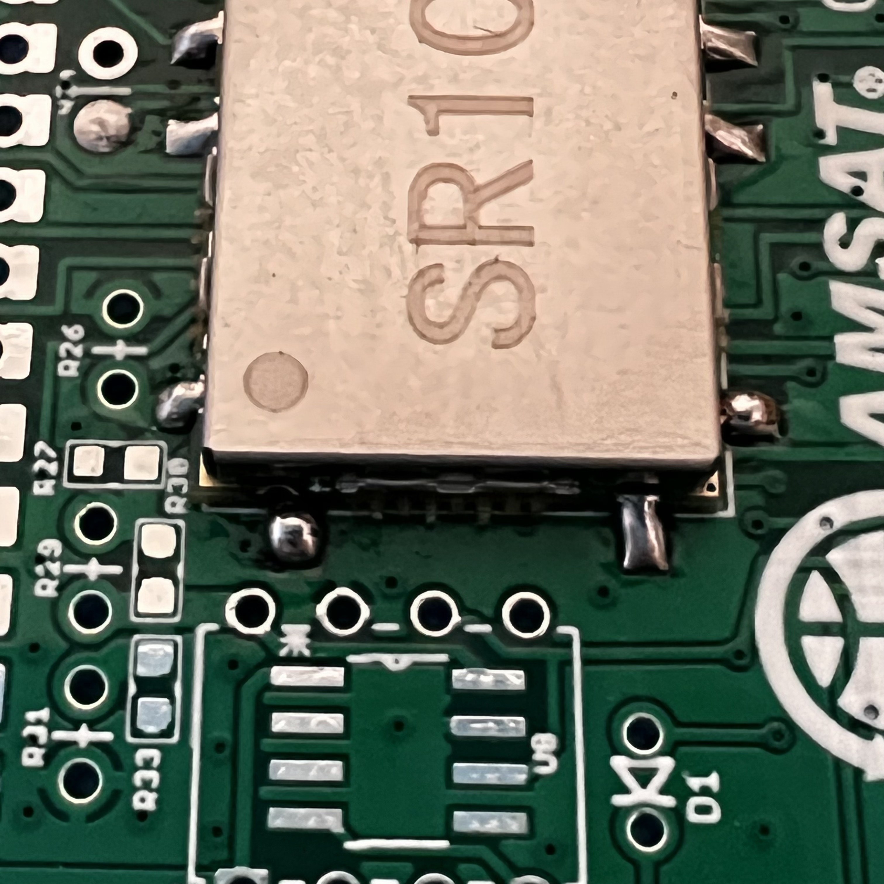
Now, both pins are fixed.
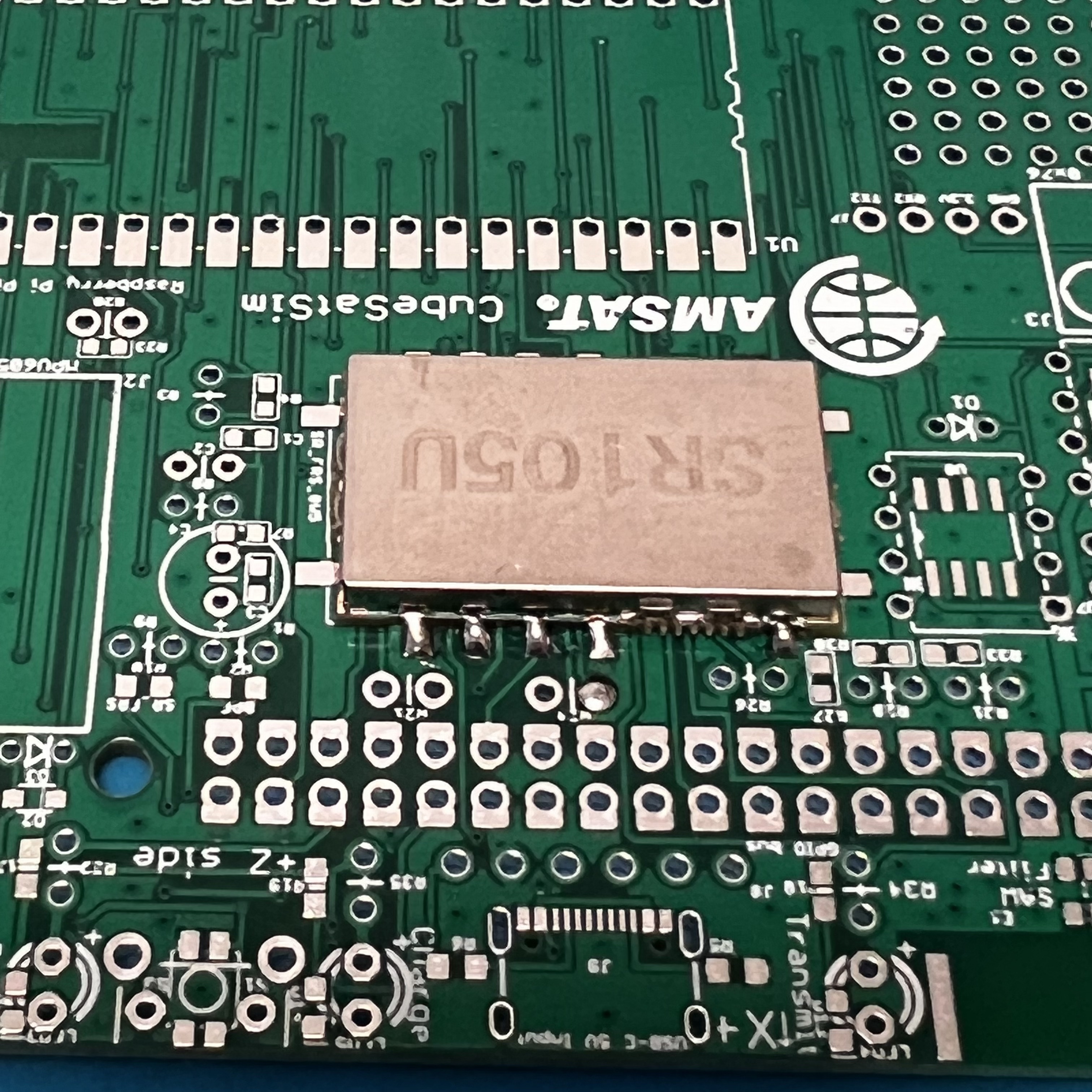
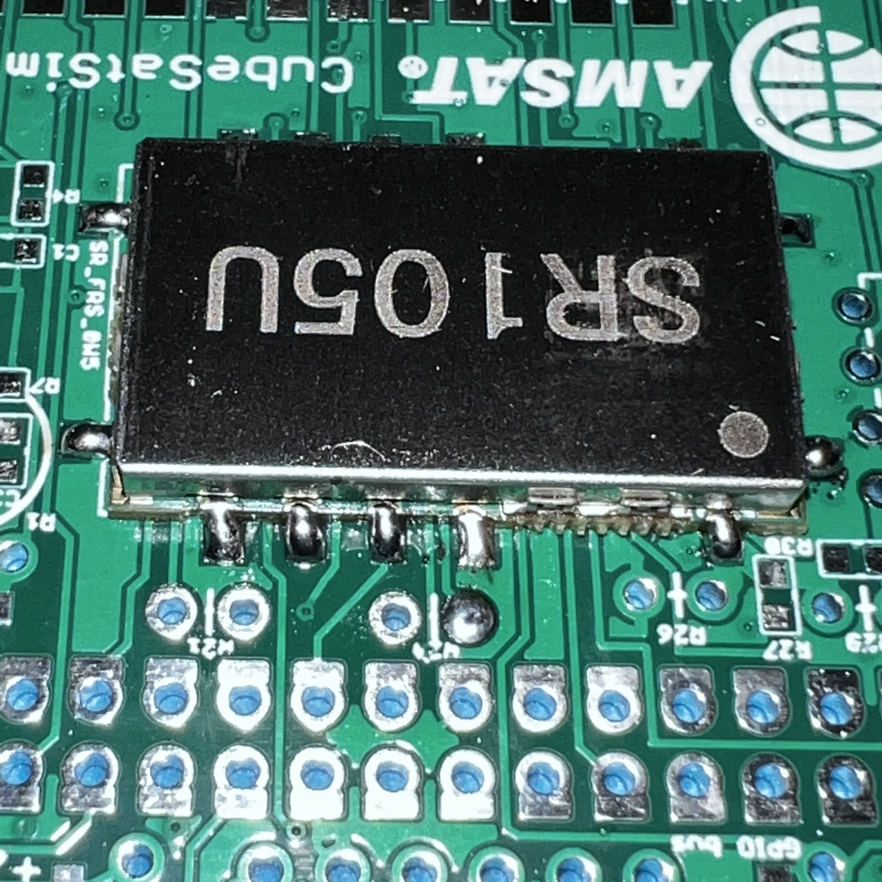
A closeup.
Next, solder the three integrated circuits (IC):
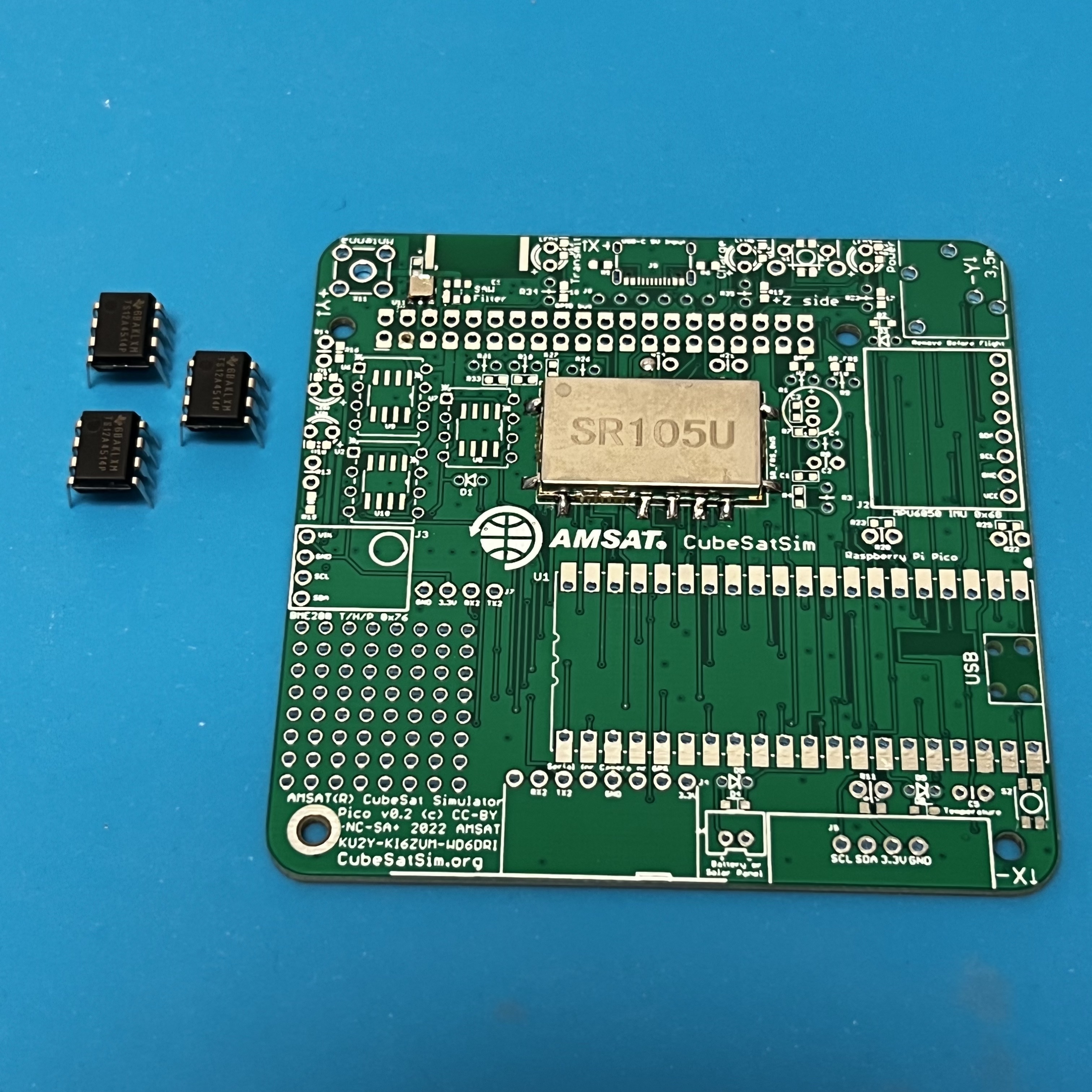
You will need to bend the pins slightly to insert them in the PCB. Pay attention to the "dot" on the IC that marks pin 1, and make sure it is in the upper left when the board is in this position.
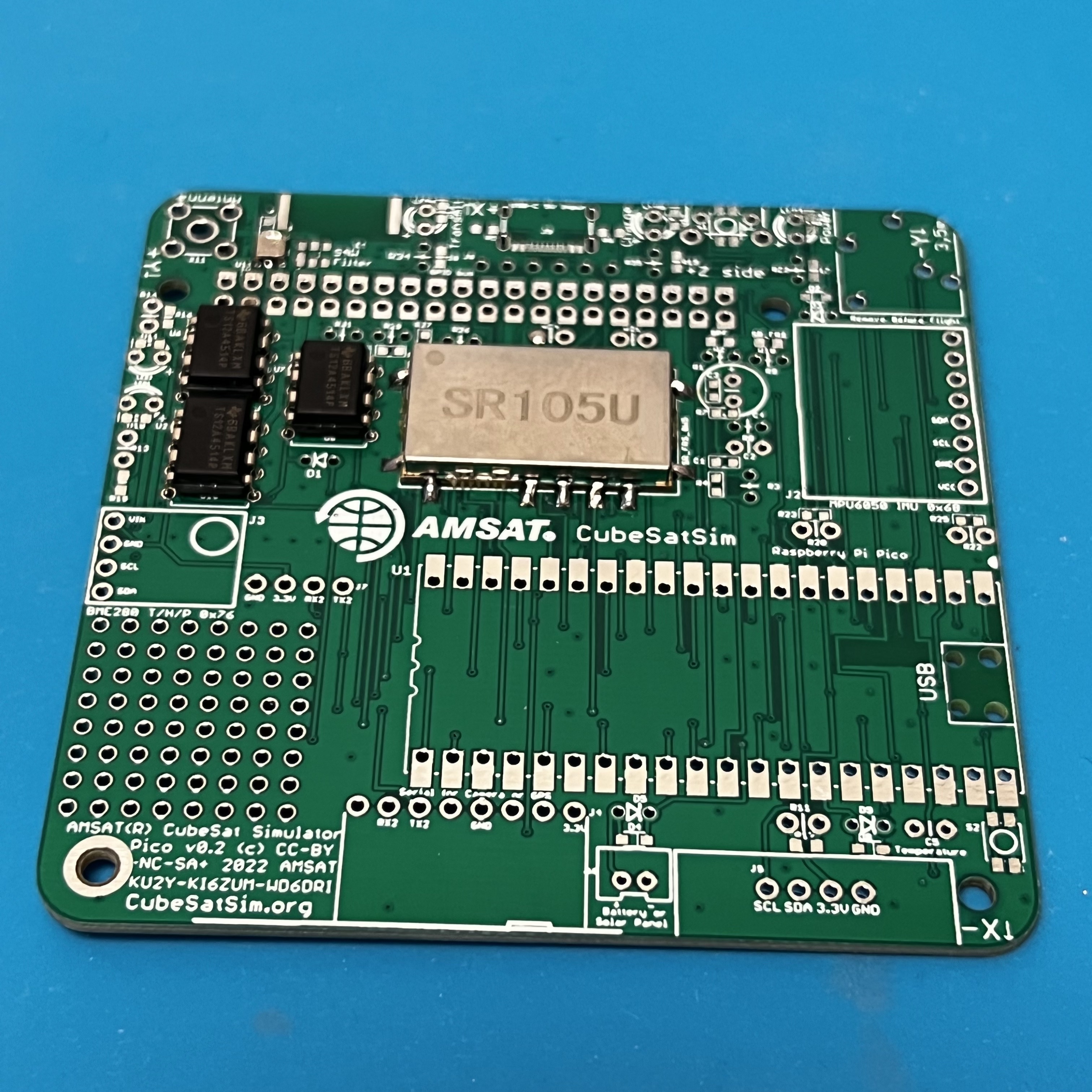
Solder only one pin on each IC, then double check the pin 1 mark and the IC is inserted correctly before soldering the rest of the pins.
Now solder the female pin headers for the Pico, BME, and MPU sensors. NOTE: You can also solder the Pico directly onto the board if you are comfortable drag soldering SMD parts.
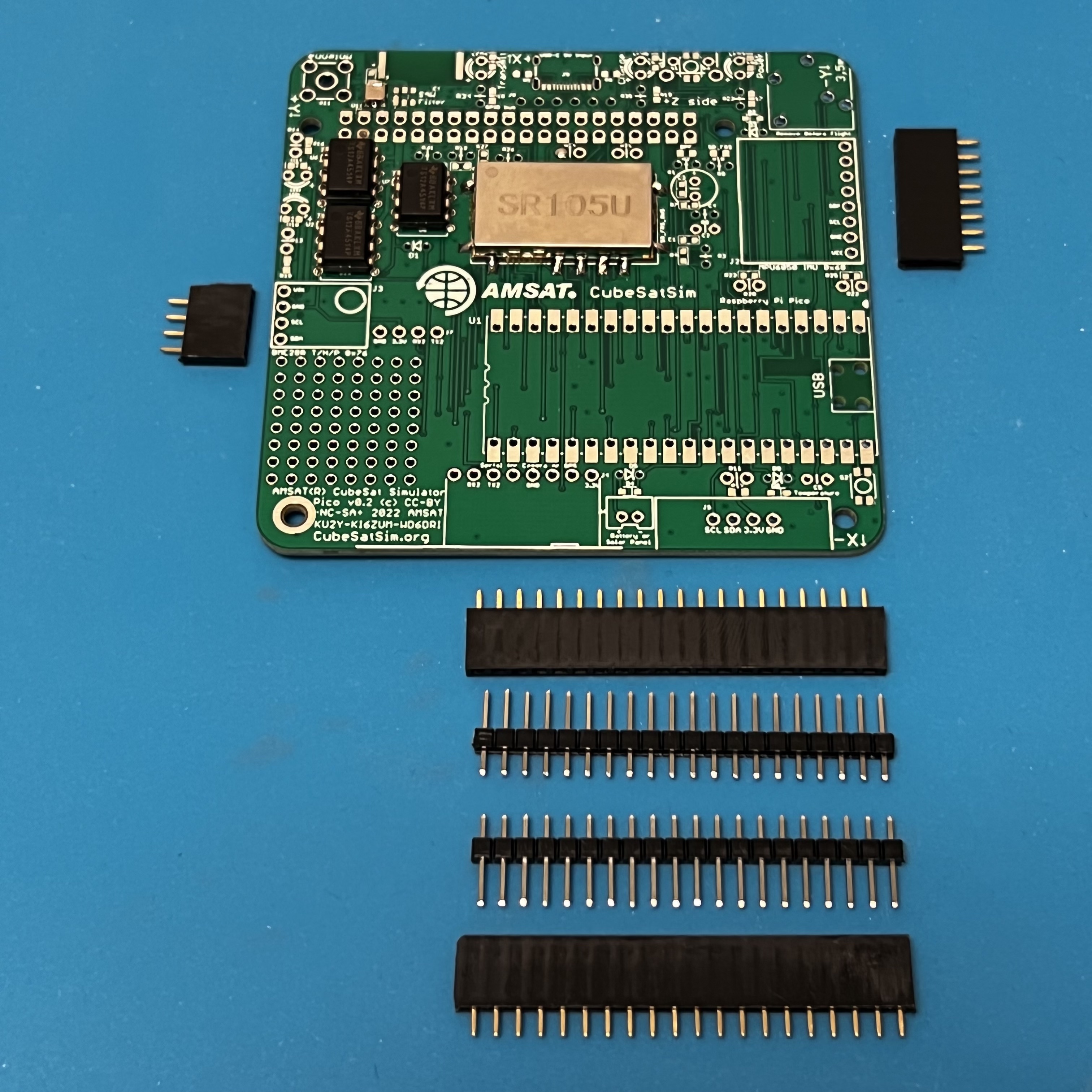
You can use the male pin headers to space and align the sockets for the Pico. Or, if you have a Pico with the male headers already soldered in (Pico H), you can plug in the Pico to set the socket spacing and alignment while you solder the first pins. Solder one pin on each side of the socket, then check alignment before soldering the remaining pins.
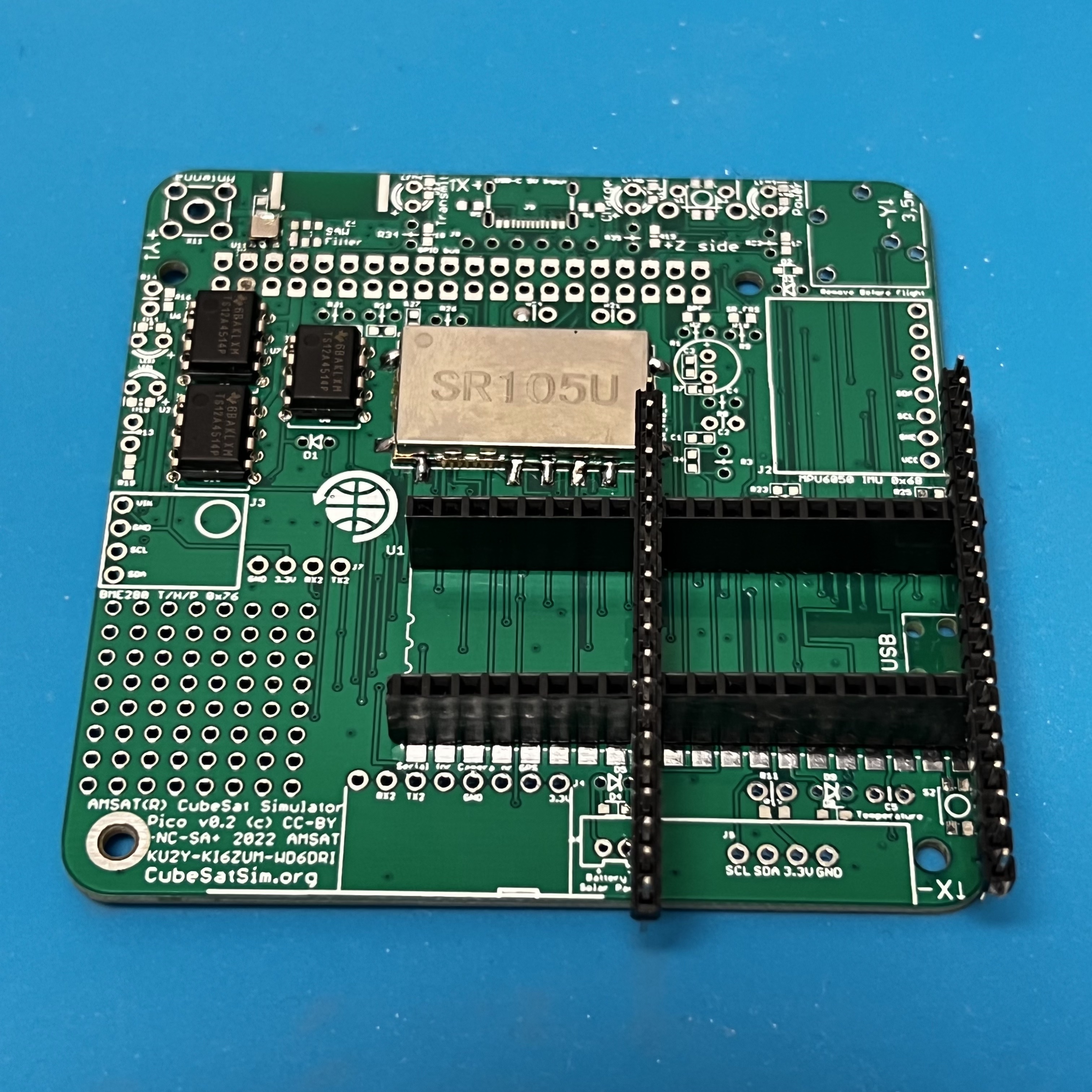
Make sure the BME and MPU female headers are in place before soldering one pin, then checking.
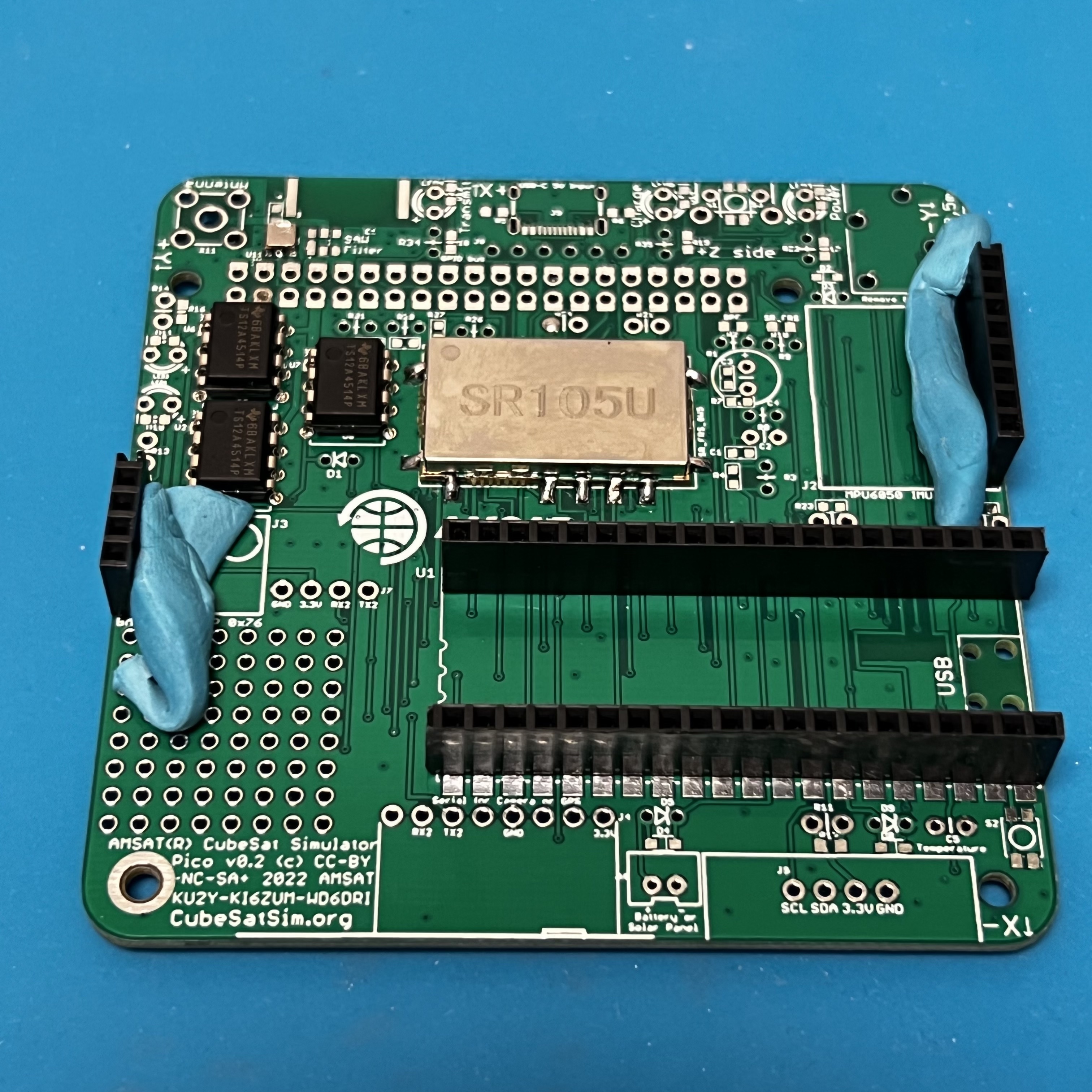
Here's how it looks with the female sockets installed:
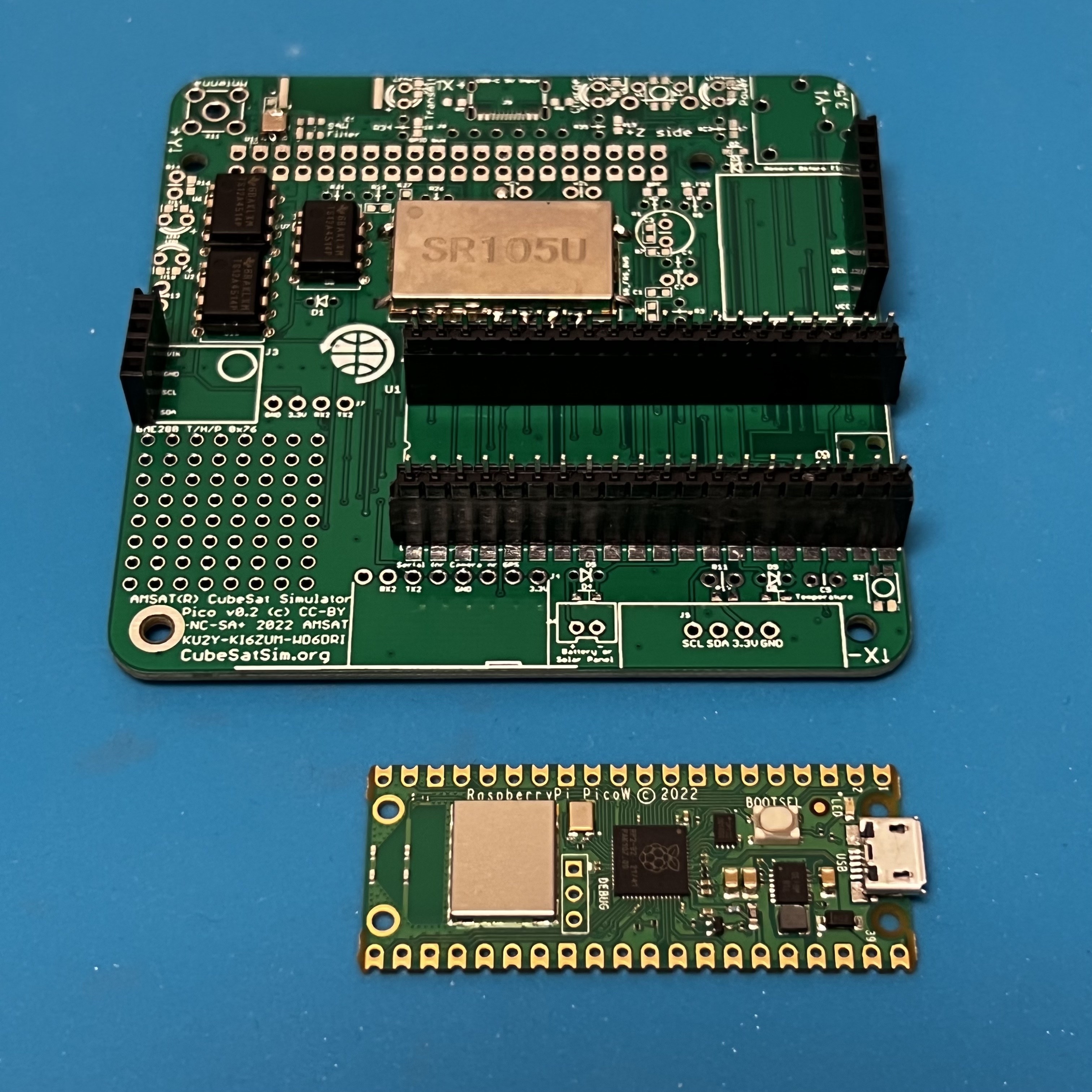
If they aren't already soldered, solder the male pins to the Pico board.
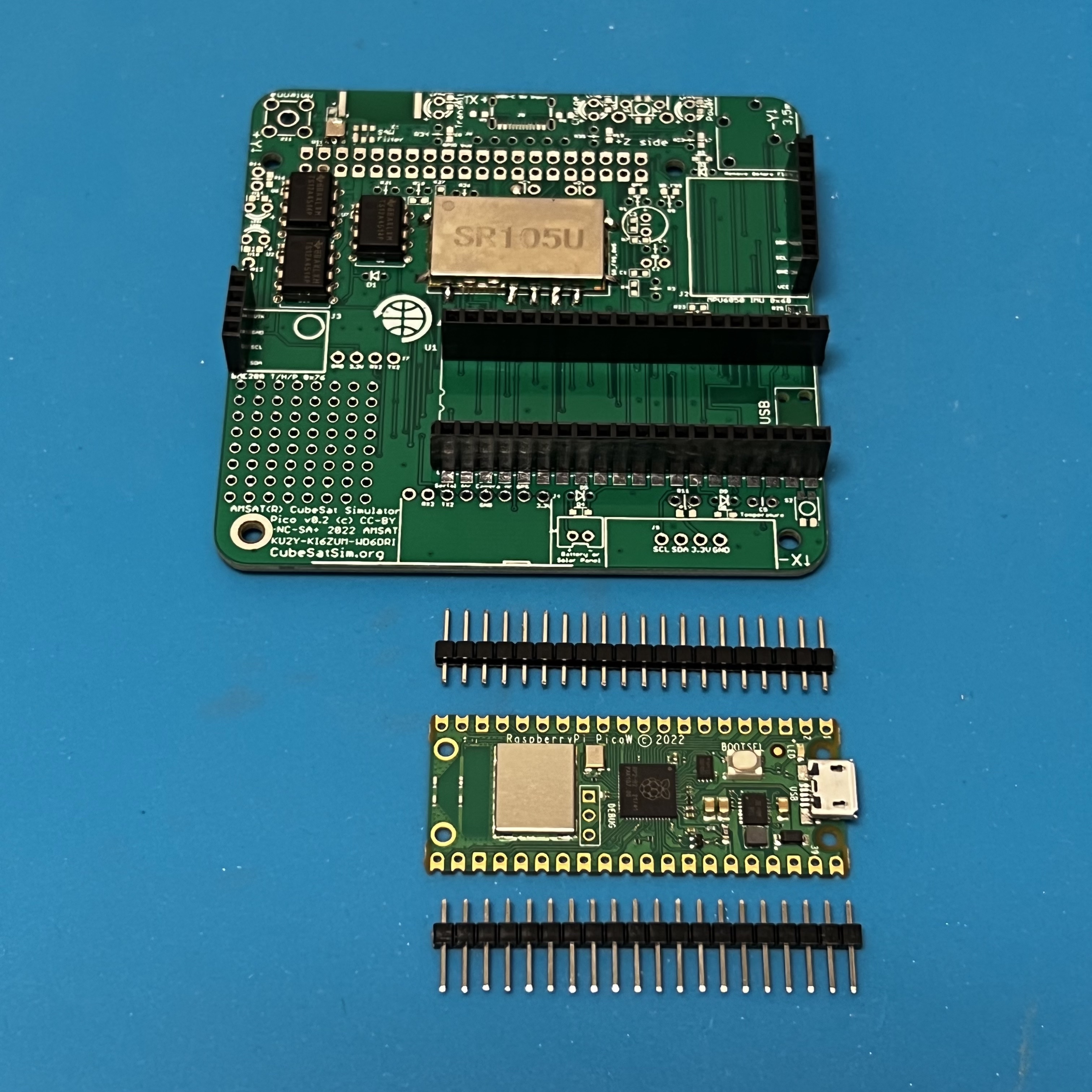
Insert the male pin header into the sockets.
Place the Pico board on top and solder the pins.
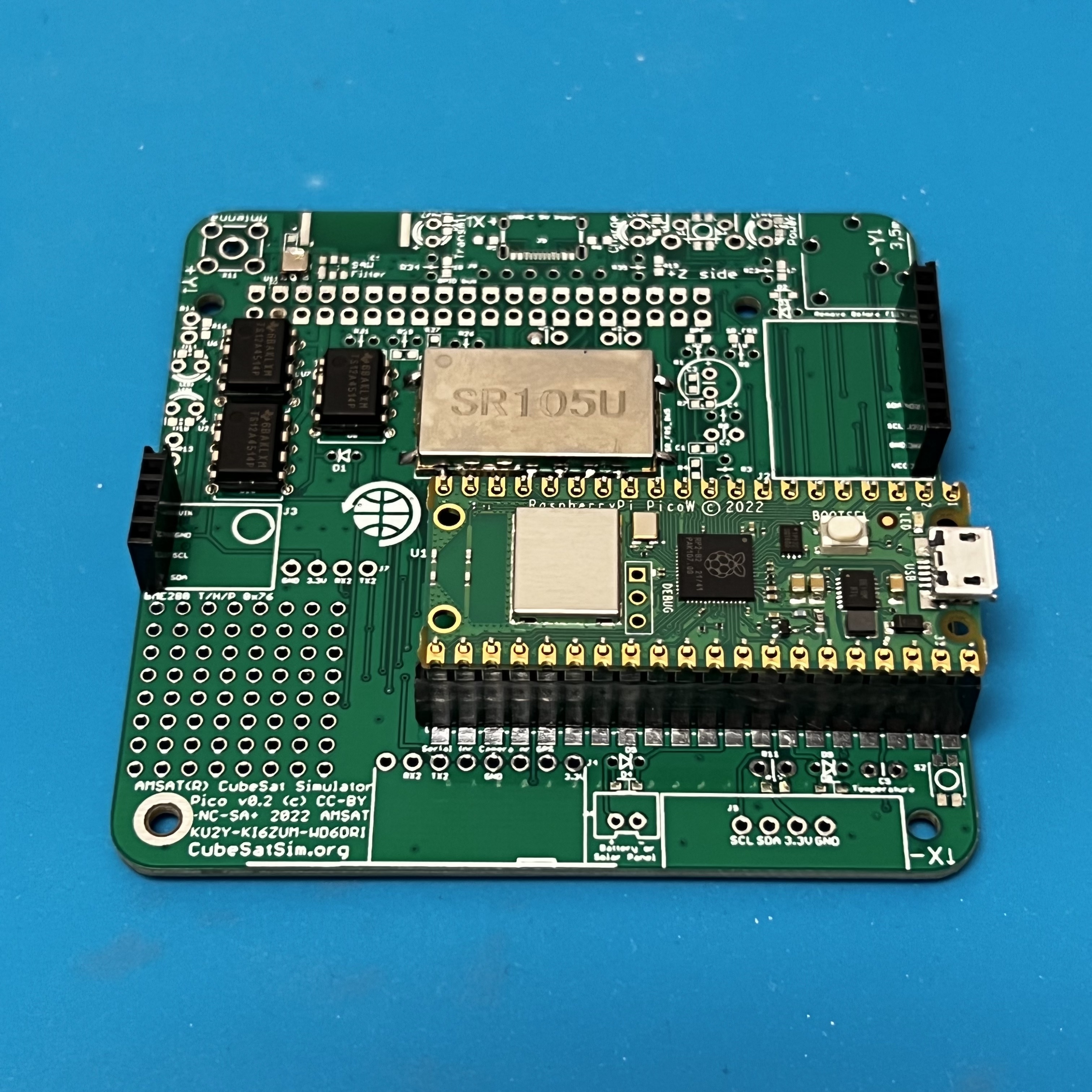
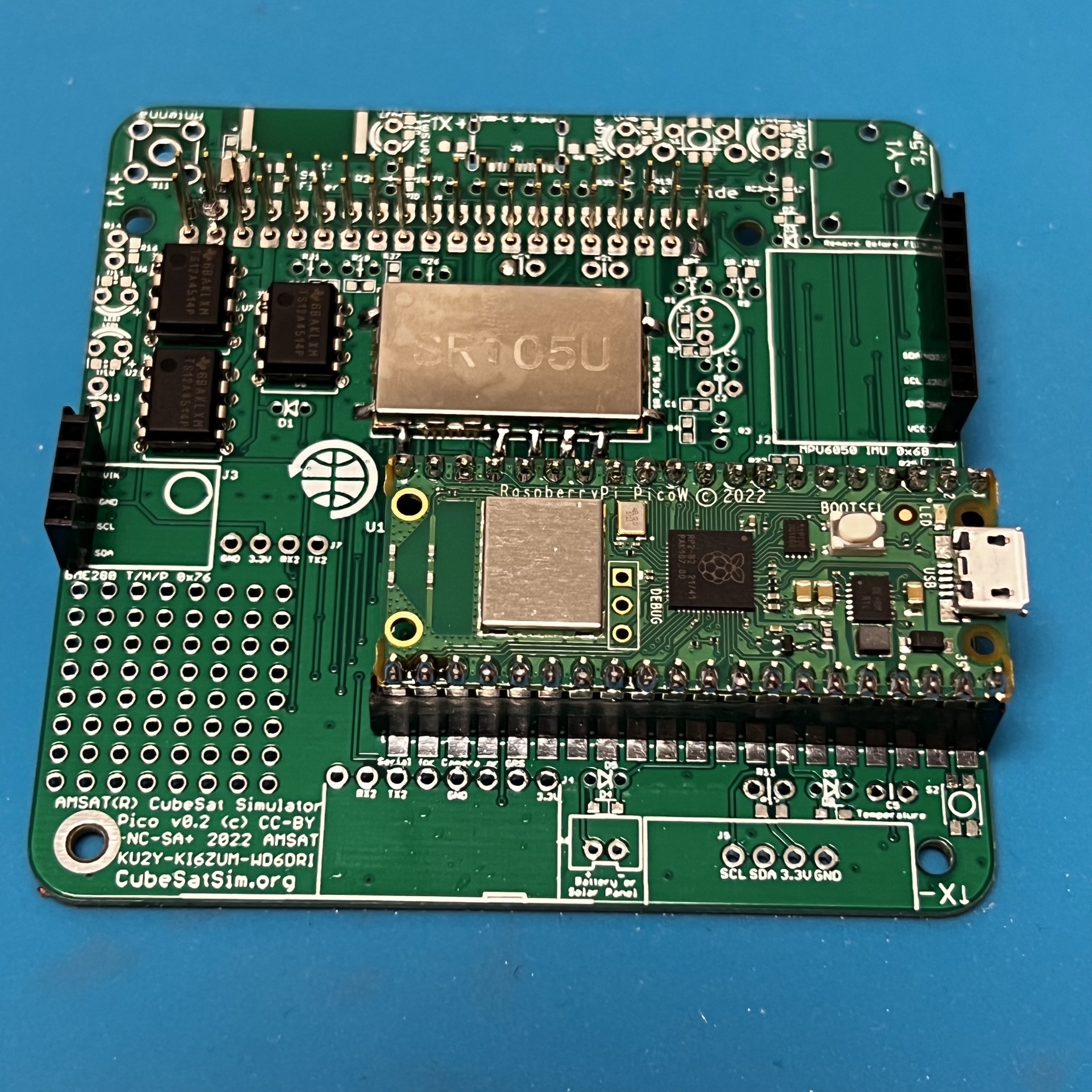
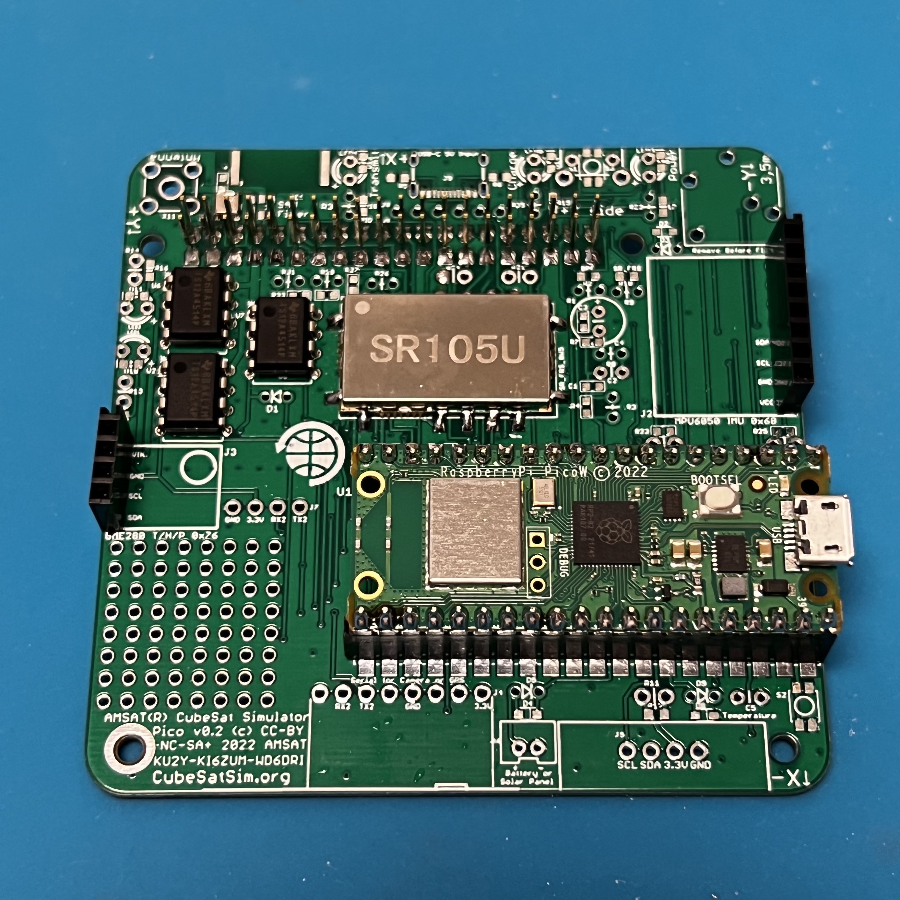
Here's how it looks when fully soldered:
Next, install the stacking GPIO header.
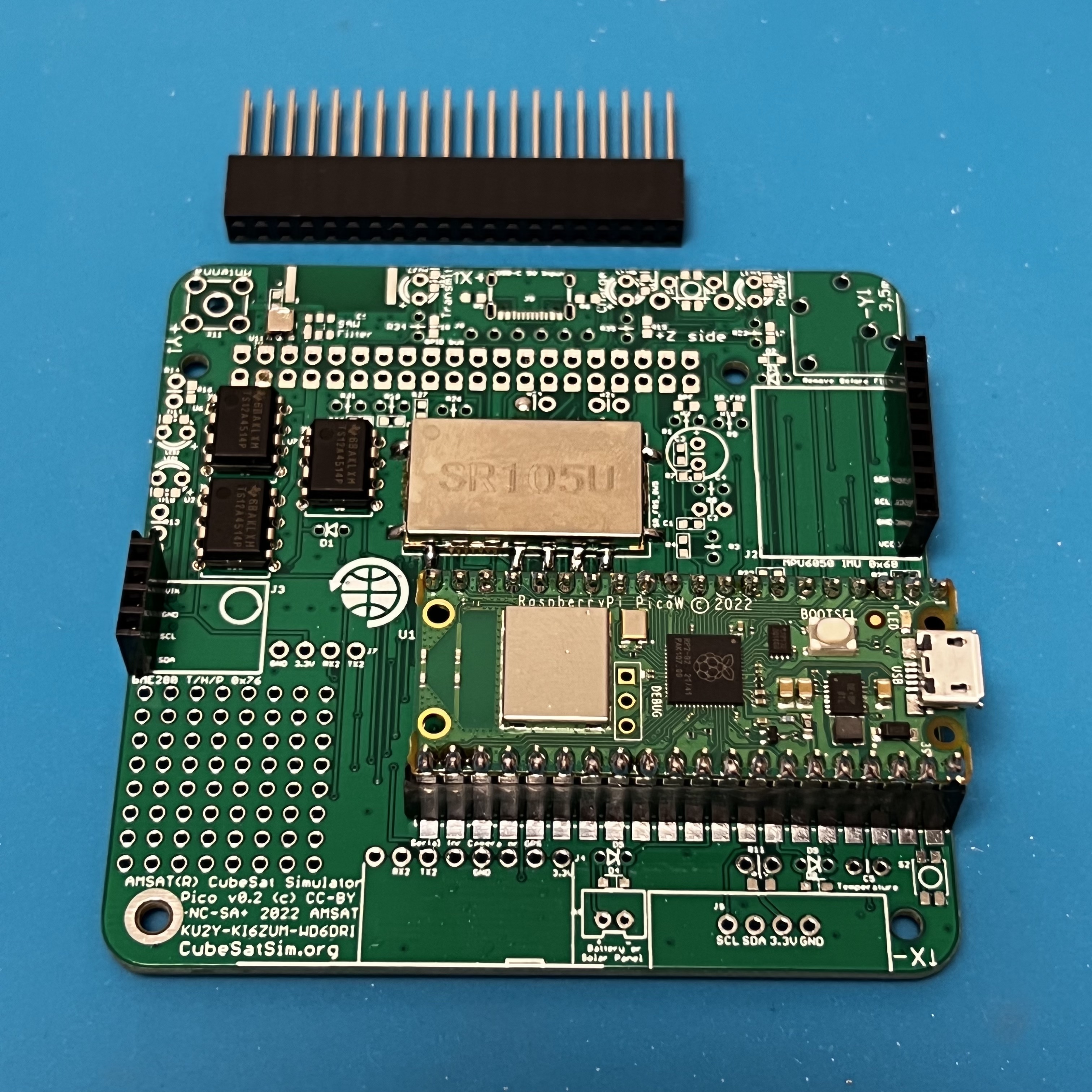
The stacking GPIO pin header is inserted on the bottom of the PCB
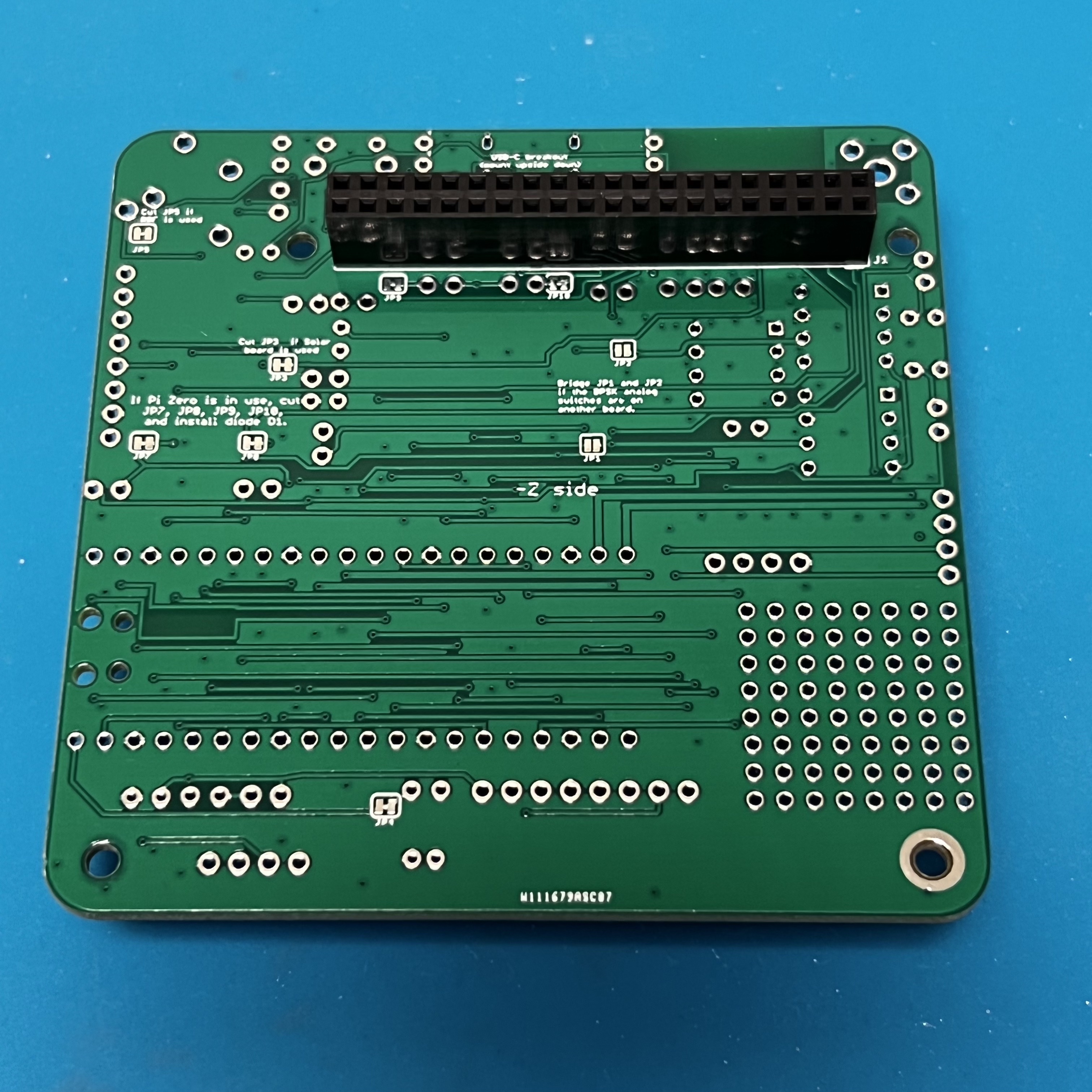
and soldered on the top. Solder one pin on either side, then carefully check that it is fully inserted and straight and mounted on the correct side.
Then solder the remaining pins.
Now install a bunch of resistors: