CubeSatSim Mini - alanbjohnston/CubeSatSim GitHub Wiki
The CubeSatSim Mini is a low cost version of the AMSAT CubeSat Simulator. It has the following functionality:
- Transmits simulated telemetry in all five modes supported by the CubeSatSim
- Transmits real sensor data from the STEM Payload Board including gyro/IMU and temperature/pressure/humidity data
- Portable operation with a USB power pack
- Picamera for SSTV image transmissions
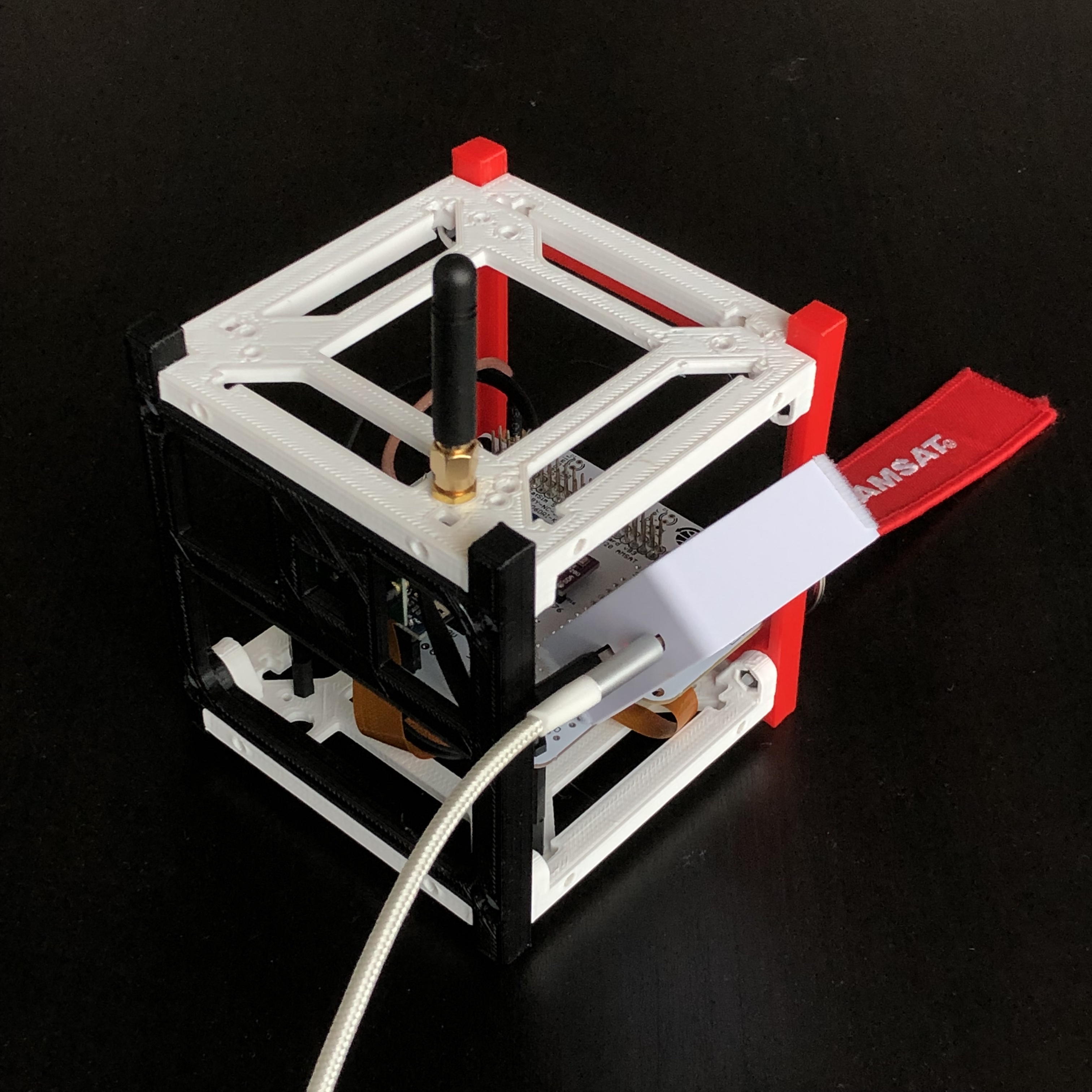
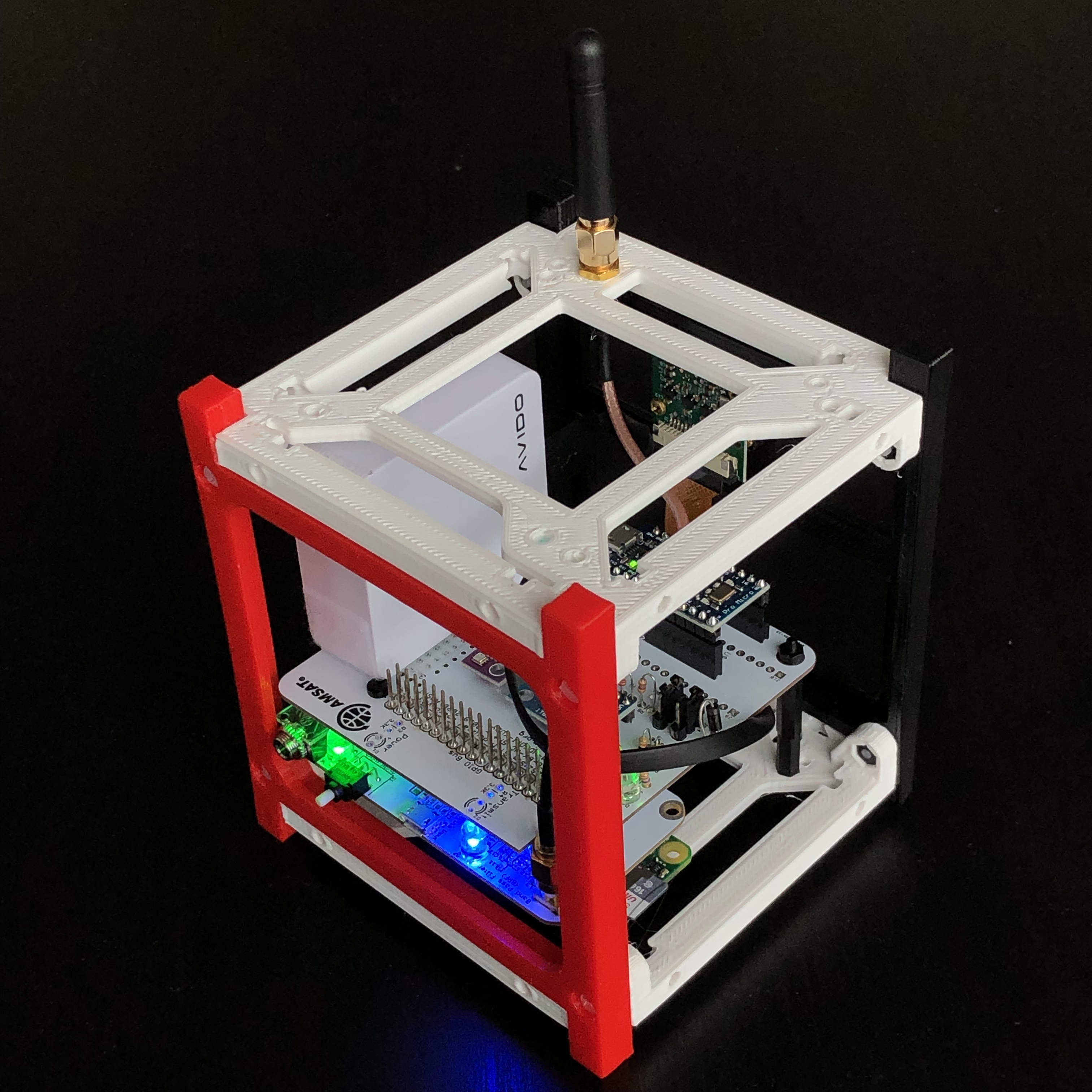
- SMA external antenna
- Controls and LEDs the same as the full CubeSatSim
- 3D printed 1U CubeSat frame
The current Beta CubeSatSim Mini has some limitations that will be fixed in the next version:
- The RBF switch is not functional. As a result, the USB power pack needs to be manually unplugged after the CubeSatSim Mini is shutdown or the USB power pack will be drained
- The micro USB charging port is not functional for charging the USB power pack. Instead, a micro USB charging cable has to be plugged into the USB power pack charging connector
- The board has its old name of the CubeSatSim Lite.
Here are the instructions for operating the CubeSatSim Mini:
-
To power up the CubeSatSim Mini, the power output from the USB power pack needs to be connected to the micro USB power input on the Raspberry Pi Zero board (the green board on the bottom of the stack). The USB A cable needs to be plugged into the micro USB power pack - the other end of this cable will be plugged into the power input micro USB connector on the Raspberry Pi. If the USB power pack is charged, within a few seconds, the small green LED activity light on the Raspberry Pi will turn on and flicker. After about 30 seconds, the green LED on the CubeSatSim Mini board will turn on
-
After the green LED on the CubeSatSim Mini board turns on, the blue transmit LED will also turn on. For some modes, the transmit LED will be on almost continuously (e.g SSTV or CW mode), or on but flashing every few seconds (FSK or BPSK mode), or mostly off but blinking on occasionally (APRS mode). If the blue transmit LED is turning on, you can listen for telemetry transmissions.
-
Your radio or ground station should receive signals at 434.9 MHz ( +/- 15 kHz). All voltage and current telemetry values are simulated since the CubeSatSim Mini does not have solar panels or current and voltage sensors.
-
You can change the telemetry mode using the pushbutton. When you press and hold the button, the green LED will start to flash. The number of flashes indicates the mode. If you press and immediately release the button, the CubeSatSim Mini will reboot, the LEDs will turn out and then turn back on again in about 45 seconds.
-
You should see real sensor data from the STEM Payload board. If you are running FoxTelem to decode the FSK or BPSK mode telemetry, look for the box labeled "Experiments" STEM Payload. It should say "STEM Payload Status OK" on the first row which shows the status, and you will see temperature, pressure, altitude, and humidity from the BME280 sensor. There is also Diode Temperature reading which is a rough estimate of the temperature from a simple diode.
-
If you are receiving APRS mode telemetry, you can also see gyro and IMU from the MPU6050 sensor. The telemetry string begins "hi hi" then has strings of three digit numbers. This is simulated current and temperature telemetry which is in AMSAT AO-7 format and can be decoded with this spreadsheet. The real sensor data is at the end beginning with "Payload OK"
-
To shutdown the CubeSatSim Min, press and hold the pushbutton until the green LED flashes slowly. The CubeSatSim Mini will then shutdown and the LEDs turn off and the Raspberry Pi shutdown. When shutdown, the Pi still draws current, so if you leave your CubeSatSim Mini like this, the USB power pack will drain in about a day. So, after shutting down, you should unplug the USB A cable from the USB power pack.
-
To charge the USB power pack, it is recommended that you shutdown the CubeSatSim Mini and disconnect the USB A cable as described in the previous step. Then, plug a micro USB charging cable with a power plug into the charging connector on the micro USB connector of the micro USB power pack. The USB power pack is held in place with velcro, so you can remove it or tilt it to get access to the connectors as shown here: