Beta Upgrade to v2.0 - alanbjohnston/CubeSatSim GitHub Wiki
CubeSatSim Beta Upgrades
If you built a Beta CubeSatSim v1.3.2 or Beta CubeSatSim Kit, there are a few upgrades you can do to have the full functionality of the v2.0
You will need to update the software by logging into your Pi Zero and connecting it to the internet, or by replacing the micro SD card with the v2.0 software.
You will also have to add some components and modifications to your hardware.
These aren't hard to to, but you will need to remove your board stack from the frame and also unstack the frame.
Here are the additional features and capabilities you can can get by doing the upgrade:
- By adding a USB sound card, OTG cable, and an audio cable, you can add DTMF and APRS command and control
- By upgrading your Pi Zero W with a Pi Zero 2W, advanced features such as command and control and other new capabilities will run reliably
- By adding a series diode in the charging circuit, you can trickle charge your battery for a longer period resulting in longer battery life and lower chance of battery damage due to over charging.
Or, you can just build a CubeSatSim v2.0 which has these improvements included.
The following sections describe how to make these modifications.
Software Upgrades
To do any of these upgrades, you will need to upgrade your CubeSatSim software. You can prepare a new micro SD card by following the Step 3 wiki instructions https://github.com/alanbjohnston/CubeSatSim/wiki/2.-Software-Install#2-software-install . You will need to configure your CubeSatSim again with your callsign, latitude and longitude, WiFi network, password change, etc. You will also need to clear any telemetry data stored in FoxTelem, or your new telemetry data won't display. You do this running FoxTelem then selecting File / Delete Payload Files then selecting Yes. This menu option will be grayed out and not available if the decoder is running. If the decoder is running, select the Input tab then select Stop to stop the decoder, then the menu option will be available.
Alternatively, you can follow these instructions with your existing micro SD card in your Pi Zero.
You will need to ssh into your Pi Zero, and your Pi Zero will need to be connected to the internet. One easy way to do both is to plug a micro USB cable from the Pi Zero to your computer following the steps here: https://github.com/alanbjohnston/CubeSatSim/wiki/2.-Software-Install#logging-into-your-raspberry-pi
Once you have logged in, type these commands:
  cd

  cd CubeSatSim

  git checkout master

  ./update
After a series of updates, this should give you the latest software. You can tell by logging back into your Pi Zero and typing:
CubeSatSim/config
And it should say v2.x at the start of the output.
Sometimes, this upgrade doesn't work. If you get errors or strange behaviors or things just seem to not be working correctly, you might still need to reflash the micro SD card.
Command and Control Modifications
Beta v1.3.2 CubeSatSims support Carrier Command and Control which uses the squelch level to detect a radio command message. The detection of a FM carrier signal at the received frequency on the transceiver module squelch pin results in the mode being incremented and the CubeSatSim rebooted.
These hardware modifications to the Beta v1.3.2.3 CubeSatSim supports radio Command and Control using a FM transmitter in the UHF band, sending either a carrier signal, or DTMF tones or APRS packets. This allows switching to a specific telemetry mode, or the turning on or off of the telemetry beacon.
Hardware
Then you will need these parts:
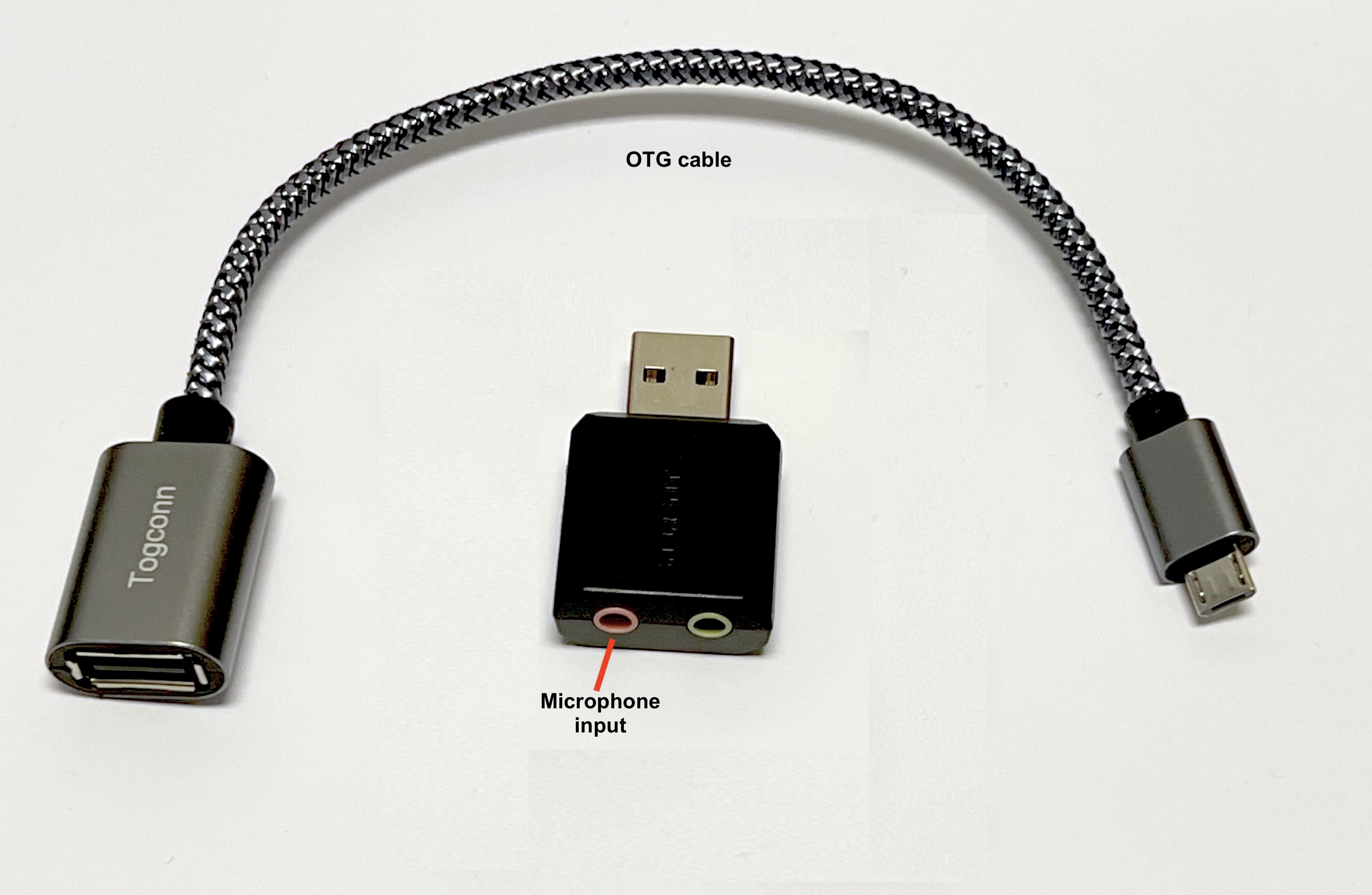
- USB sound card that plugs into the Pi Zero https://www.amazon.com/dp/B00IRVQ0F8/
- OTG cable that plugs into the micro USB on the Pi Zero and the sound card plugs into it https://www.amazon.com/dp/B0BX9FSCFH/ 210mm length
- 3.5mm plug (same as the RBF plug) https://www.digikey.com/product-detail/en/cui-devices/MP-3502/102-4775-ND/9486669
- JST jumper wire (same as the ones soldered on the solar panels), although any pair of wires will work since we will cut off the JST connector.
First, cut off the JST connector and discard.
Solder the red wire to the center of the plug and the black wire to the outside of the plug.
On the top of the Solar PCB, solder the red wire to GPIO pin 24 and the black wire to GPIO pin 20:
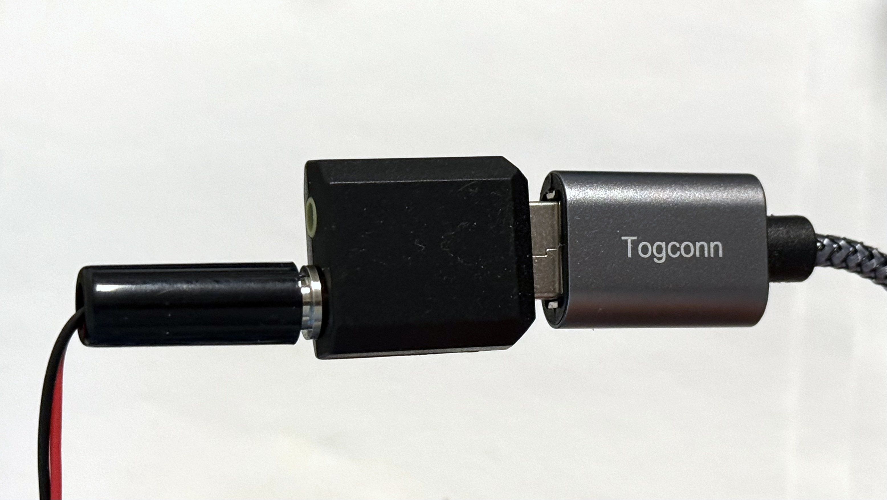
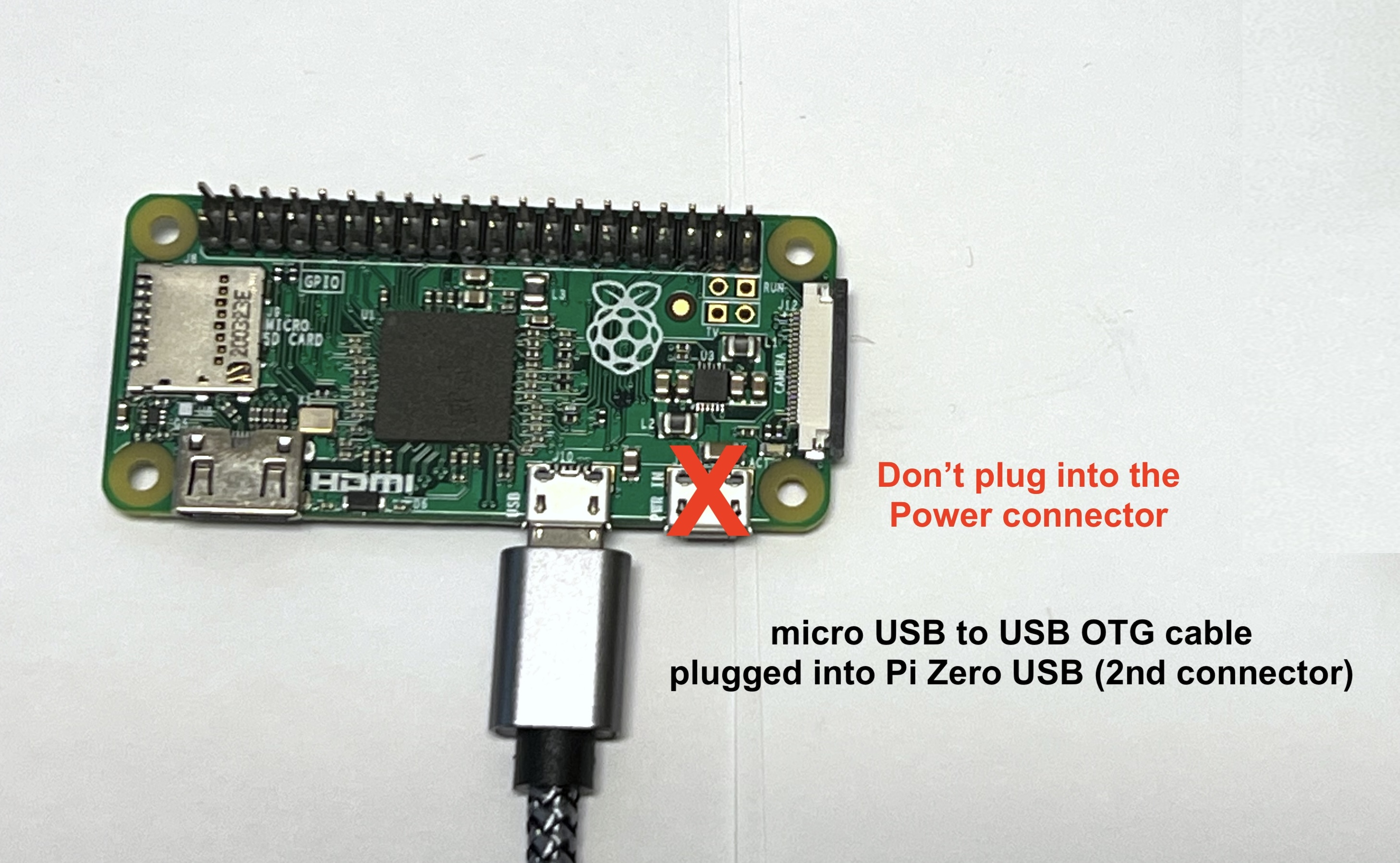
Plug the 3.5mm side of the jumper cable into the Microphone connector (pink connector) of the USB sound card. Plug the micro USB side of the OTG cable into the Pi Zero micro USB connector (NOT the Power micro USB connector!)
Here's how it looks on the bottom of the board stack:
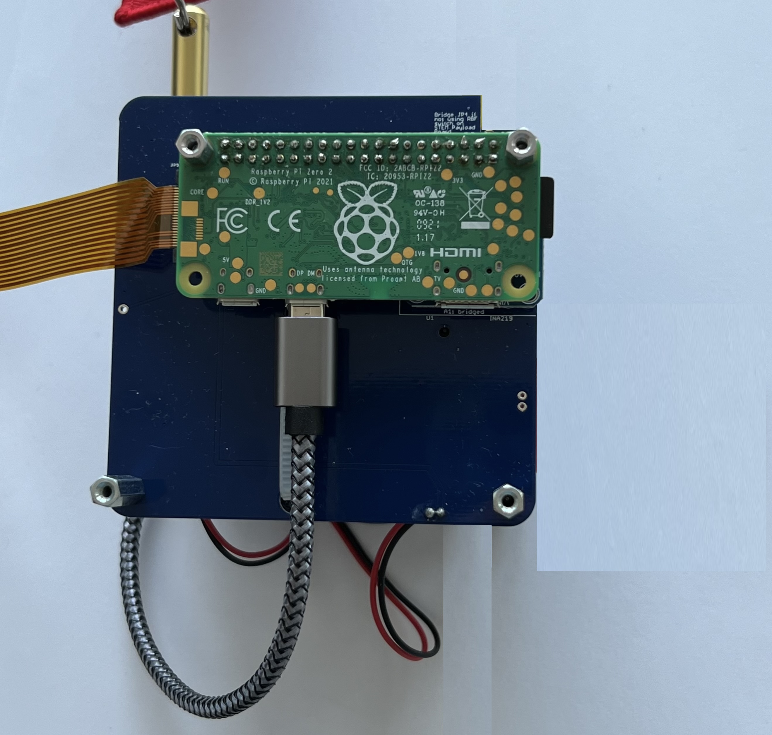
And the top of the board stack:
Refer to Step 8 for how to route the OTG cable and sound card in the frame. https://github.com/alanbjohnston/CubeSatSim/wiki/8.-Board-Stack
You can now try out Command and Control using https://github.com/alanbjohnston/CubeSatSim/wiki/Command-and-Control
Pi Zero 2W Upgrade
The version 2 hardware and software will run on a Raspberry Pi Zero W, but only just. To get reliable operation and future features, you can upgrade to a Raspberry Pi Zero 2W.
You just need to unplug the Pi Zero at the bottom of your board stack and plug in a Pi Zero 2W instead. You can buy a Pi Zero 2W using the RPi Locator tool: https://rpilocator.com/?country=US&cat=PIZERO2 If possible buy one with the 40 pin GPIO header pins already installed. If not, you will need to purchase the pin header and solder it in yourself: https://www.digikey.com/en/products/detail/sullins-connector-solutions/PREC020DAAN-RC/2774874
You will need to unscrew the standoffs to unplug the old Pi Zero.
You will also need to upgrade the micro SD card or flash a new SD card as described in the earlier Software Upgrade section.
Charging Modification
Beta v1.3.2 CubeSatSims had just one series charging diode. By adding a second 1N5817 diode, you can improve the charging and battery reliability.
The modification needed will depend on the exact version of your Beta STEM Payload PCB.
v1.3.2, v1.3.2.1 through v1.3.2.2
Here's what your PCB will look like:
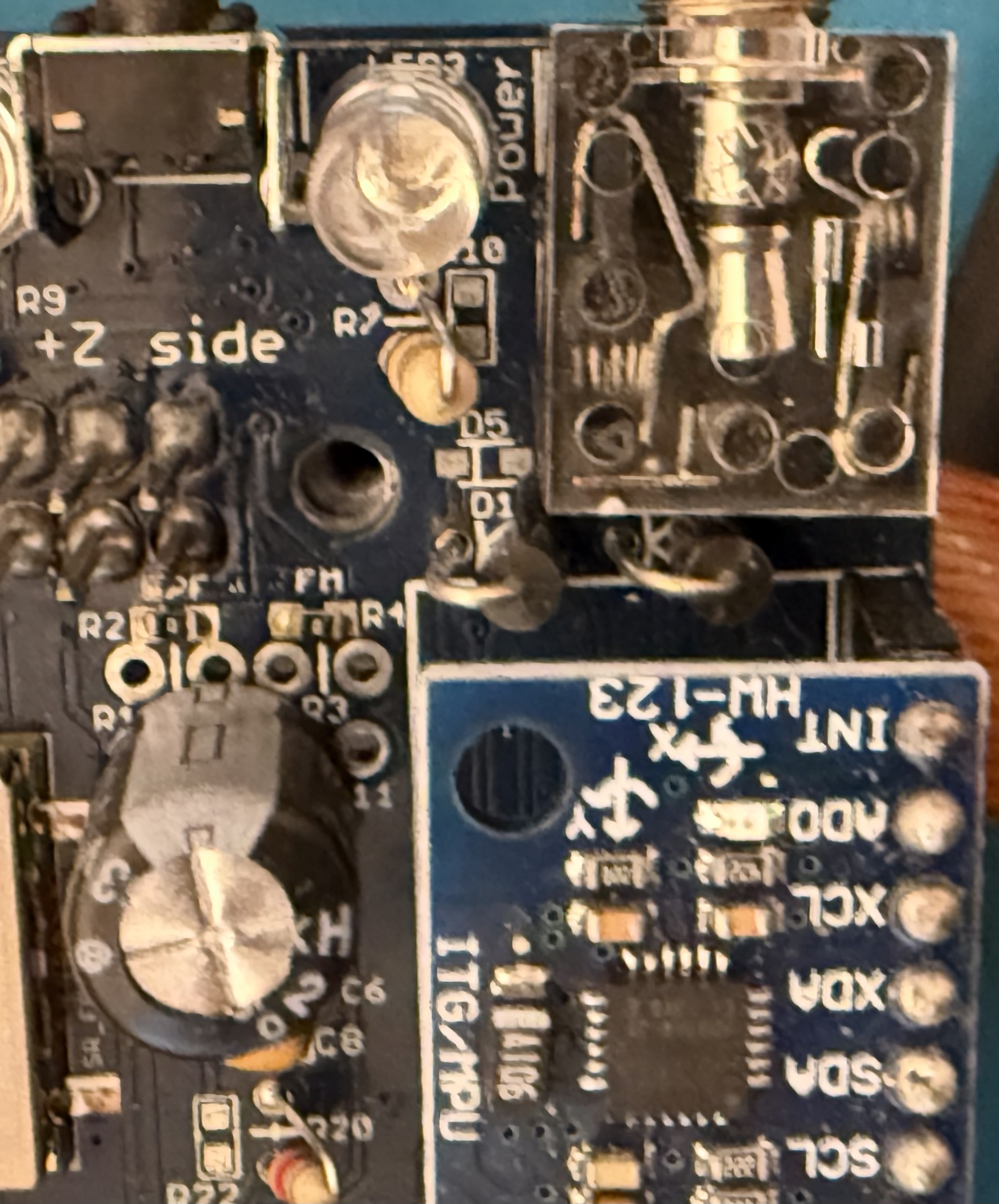
First, find your charging diode D1. It is next to the Remove Before Flight (RBF) switch. The place for the second diode is D4 which is just to the right of D1. It will look like this:
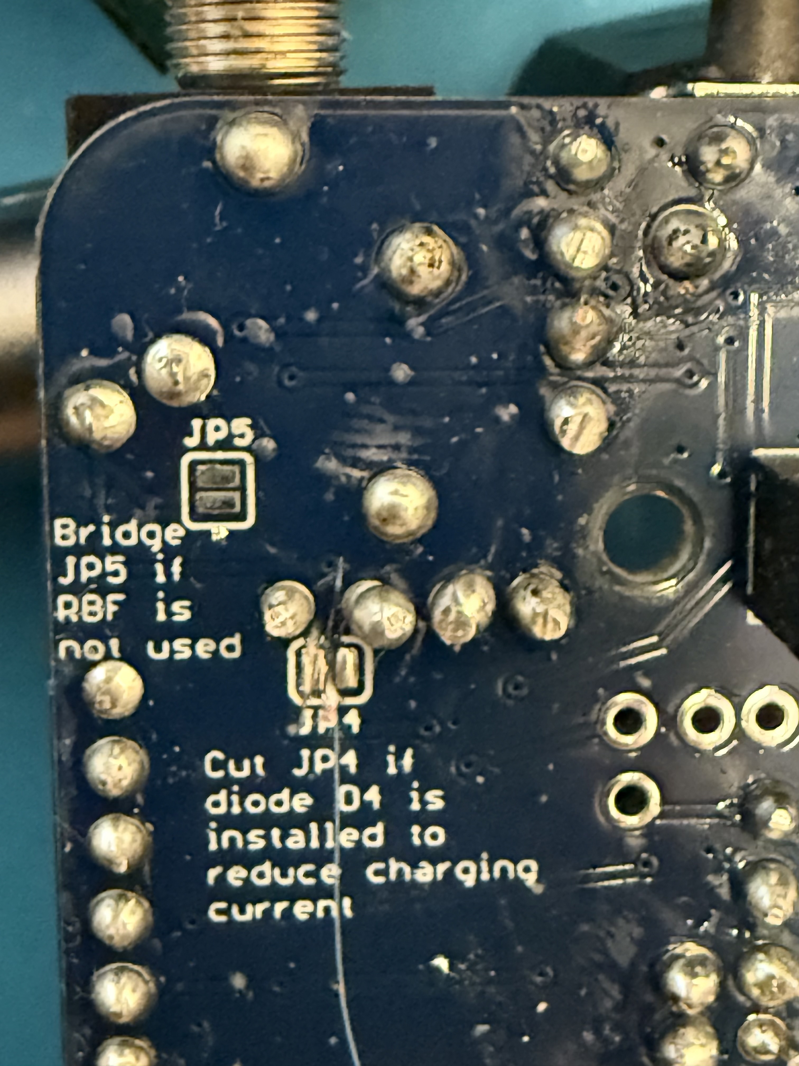
Here's how it looks on the bottom of the PCB:
You will need to cut the trace on pad JP4 on the bottom and install another 1N5817 diode as D4 next to D1 https://www.digikey.com/en/products/detail/on-semiconductor/1N5817RLG/807254 o
You need to use a knife to cut the pad JP4. It doesn't need to look pretty, as long as the trace is cut:
This is what it will look like when you have finished:
v1.3.2.3 or v1.3.2.4
Here's what your PCB will look like:
Diode D1 is in the top right next to the Remove Before Flight switch (RBF). You need to cut the existing diode D1 and solder another diode in series with it. Here's how it looks when complete:
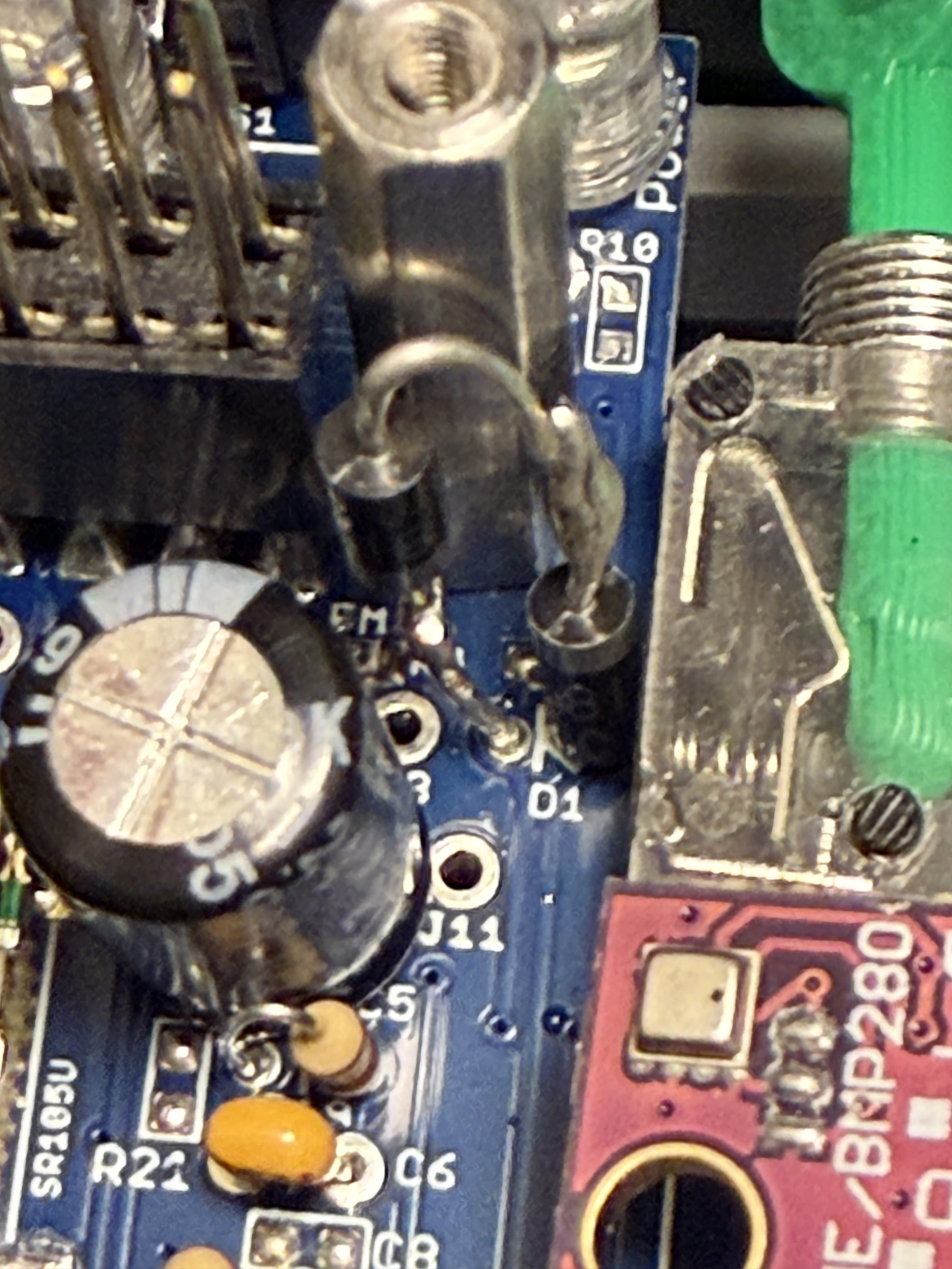
Here's how to do it. This board only shows the diode D1 for clarity:
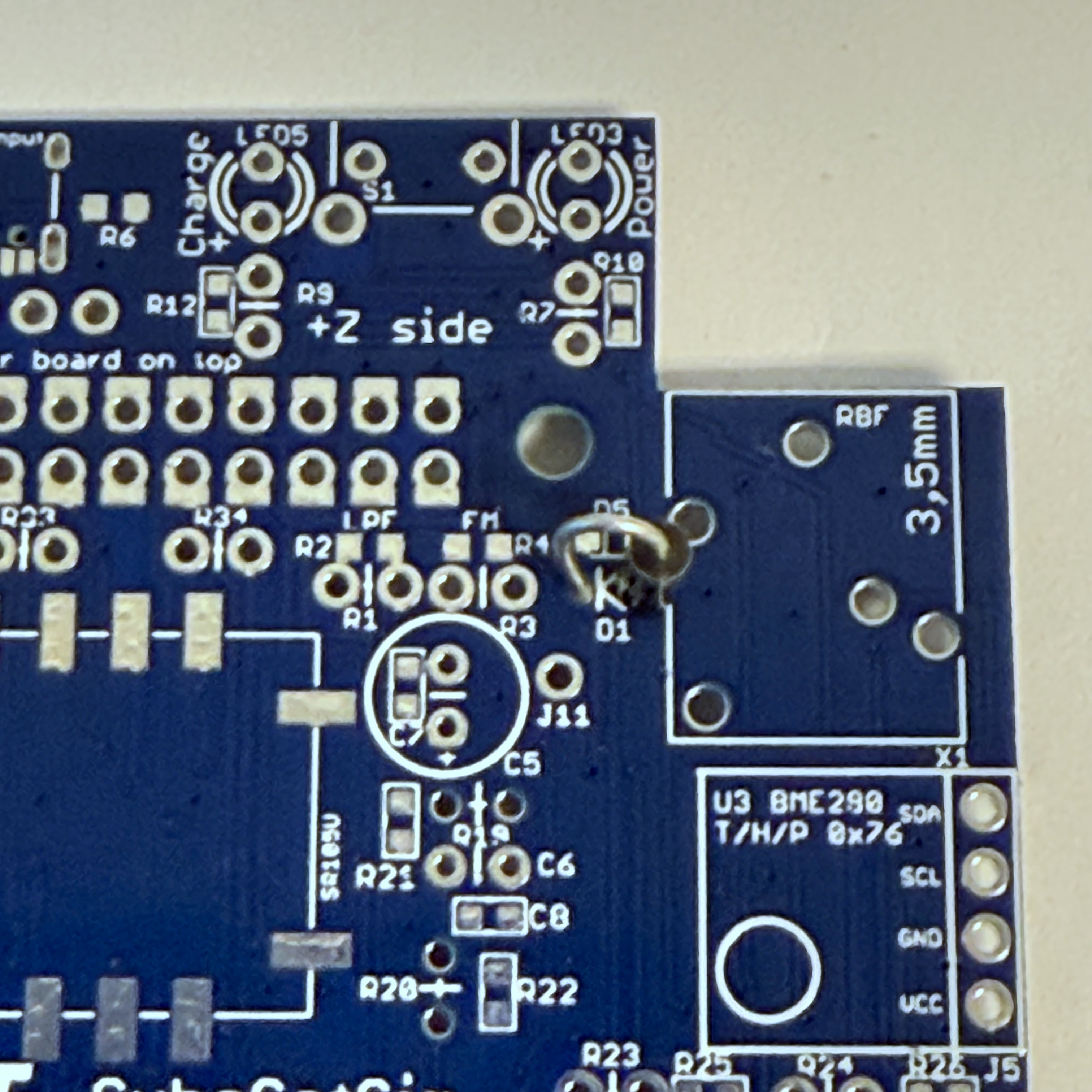
Cut the diode lead at its highest point:
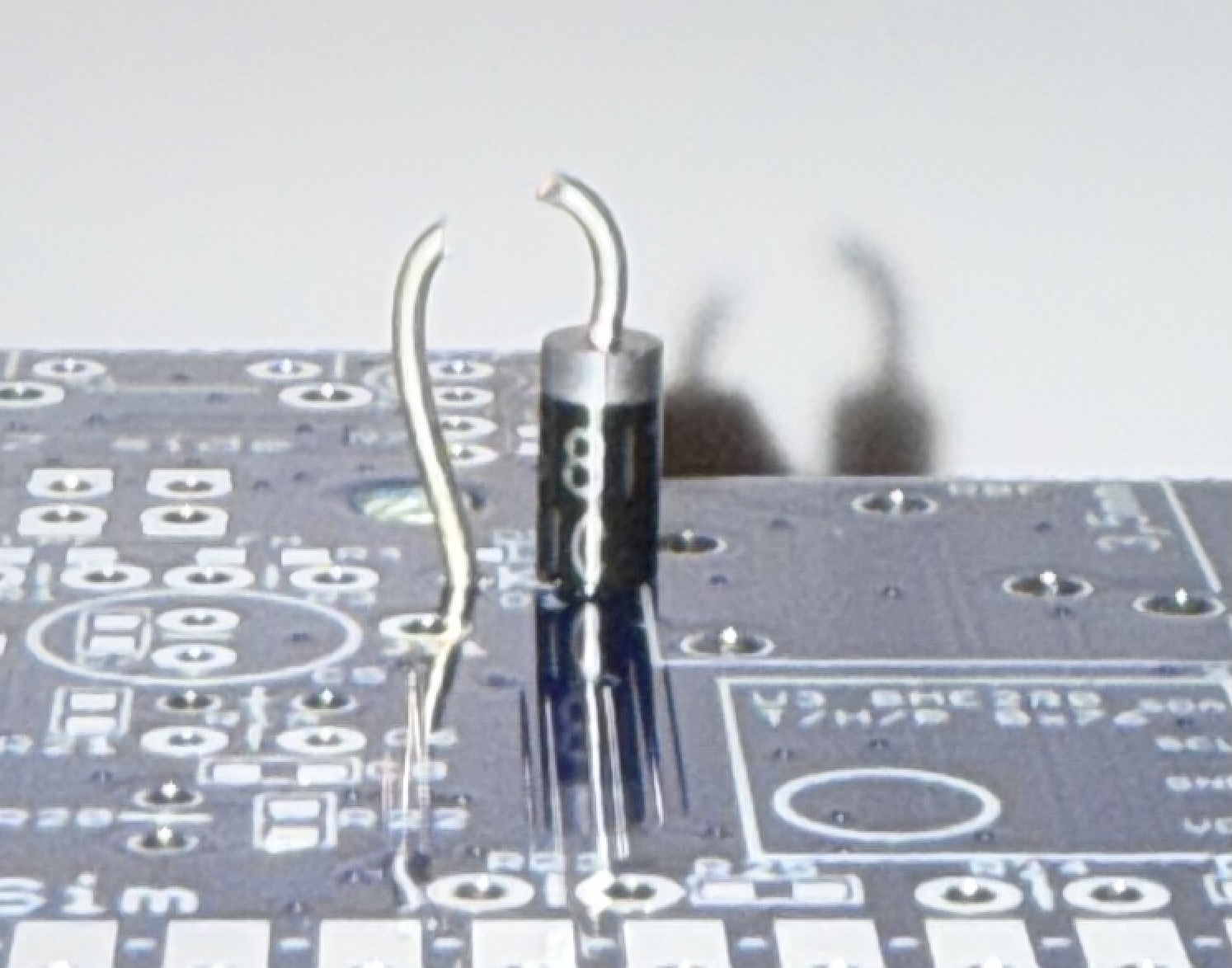
Solder a new 1N5817 diode https://www.digikey.com/en/products/detail/on-semiconductor/1N5817RLG/807254 upside down to the wire side:
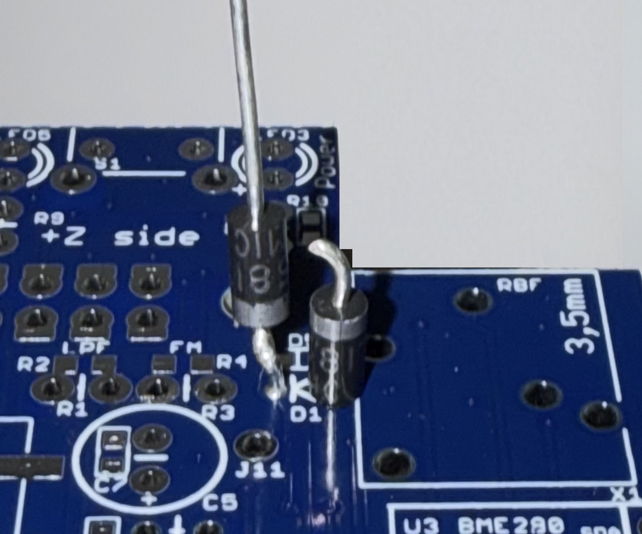
Bend the wire over and trim next to the existing diode and solder:
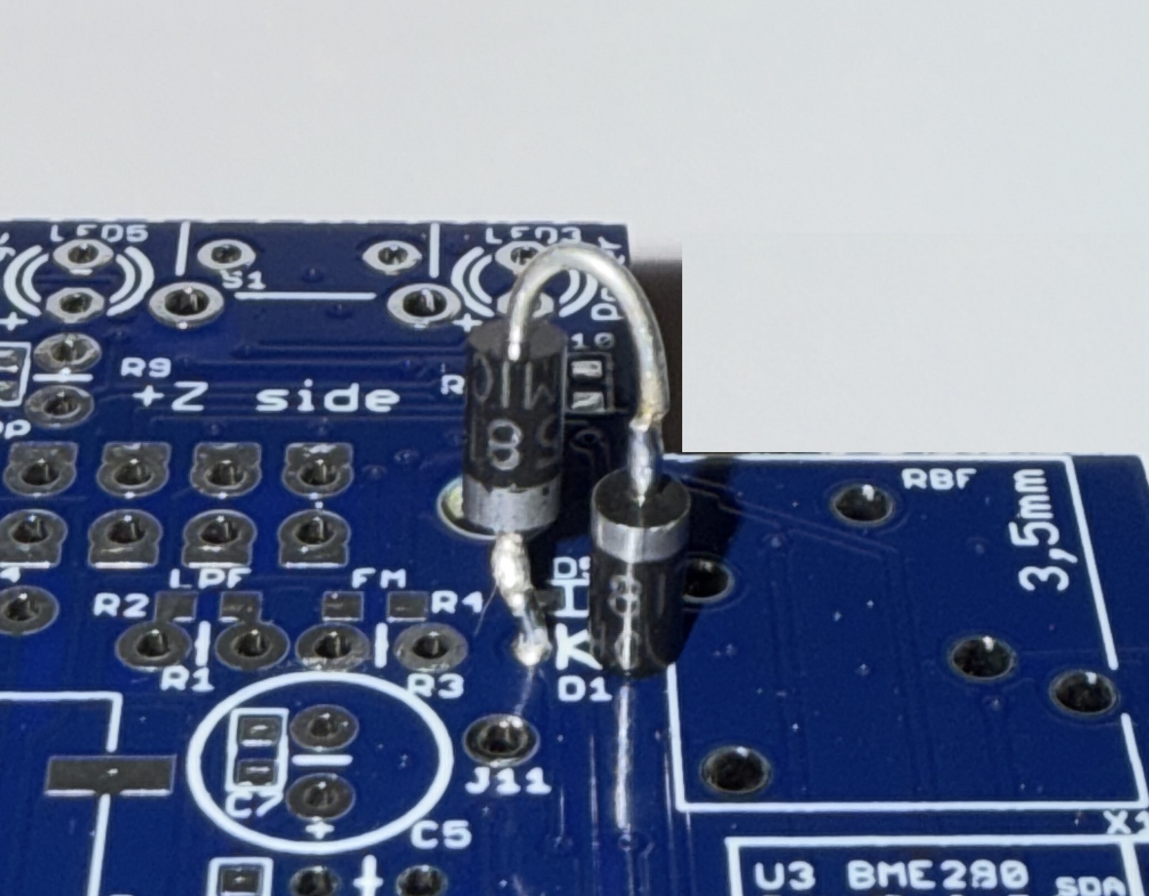
Now, you can safely trickle charge your battery for 8 hours or longer. You will notice a longer battery life after a long trickle charge.