9. Board Stack - alanbjohnston/CubeSatSim GitHub Wiki
If the images in this page fail to load, you can download a PDF of the page.
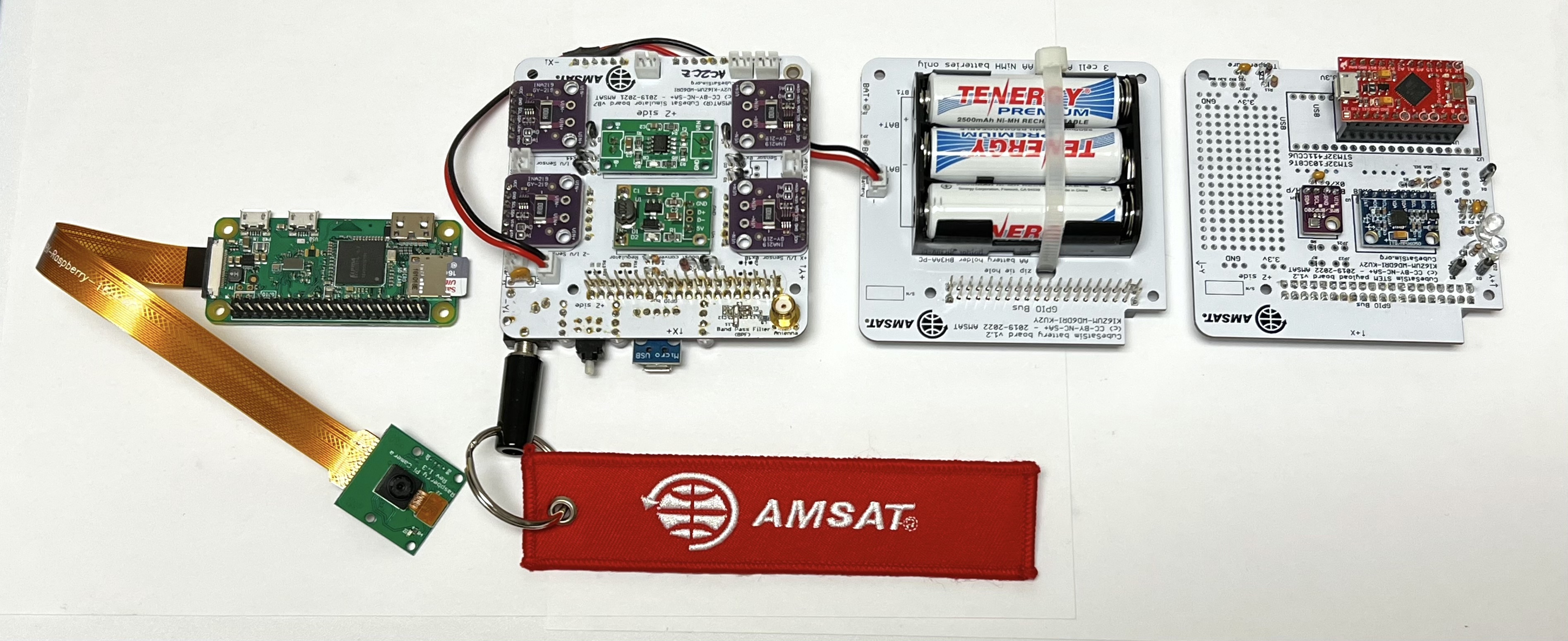
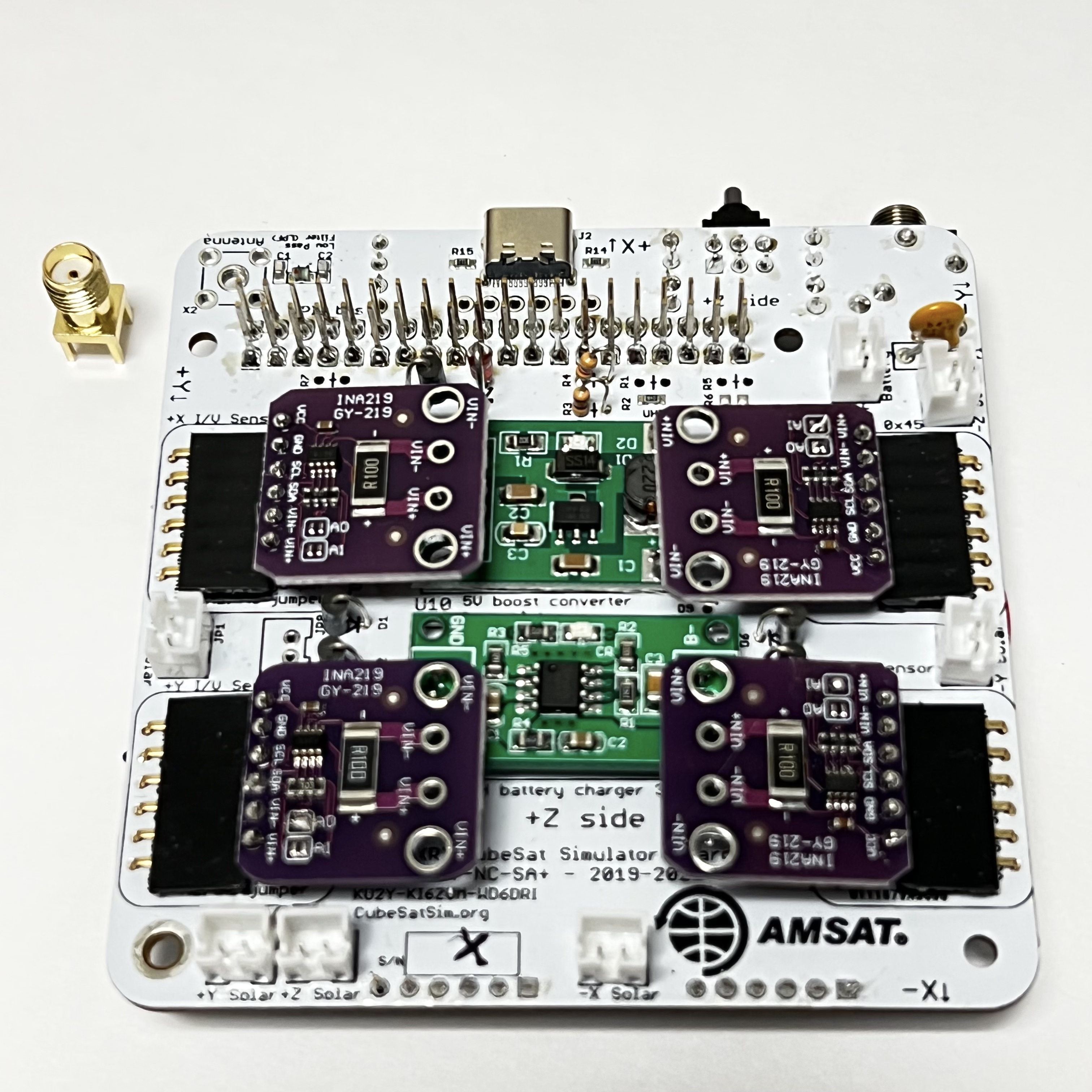
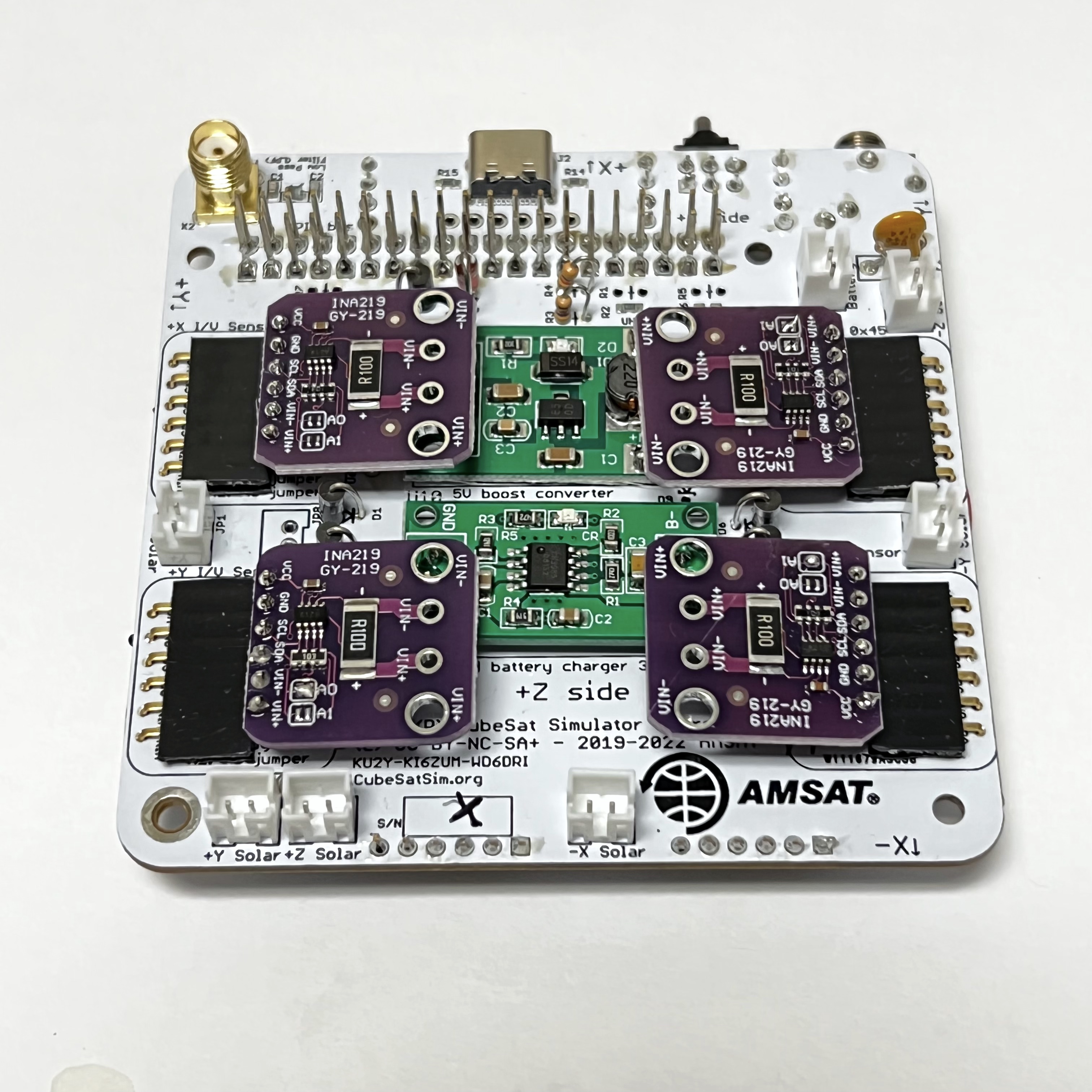
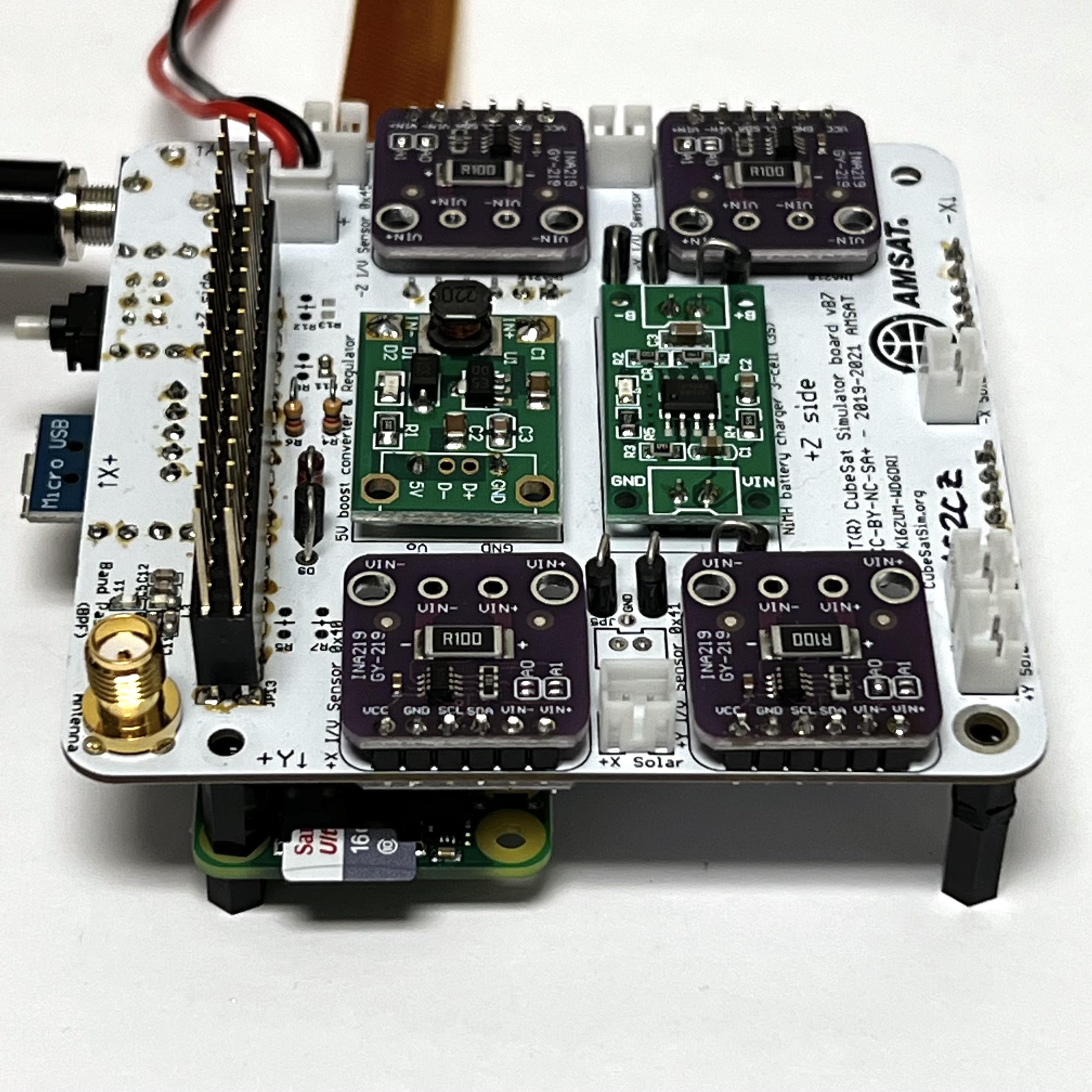
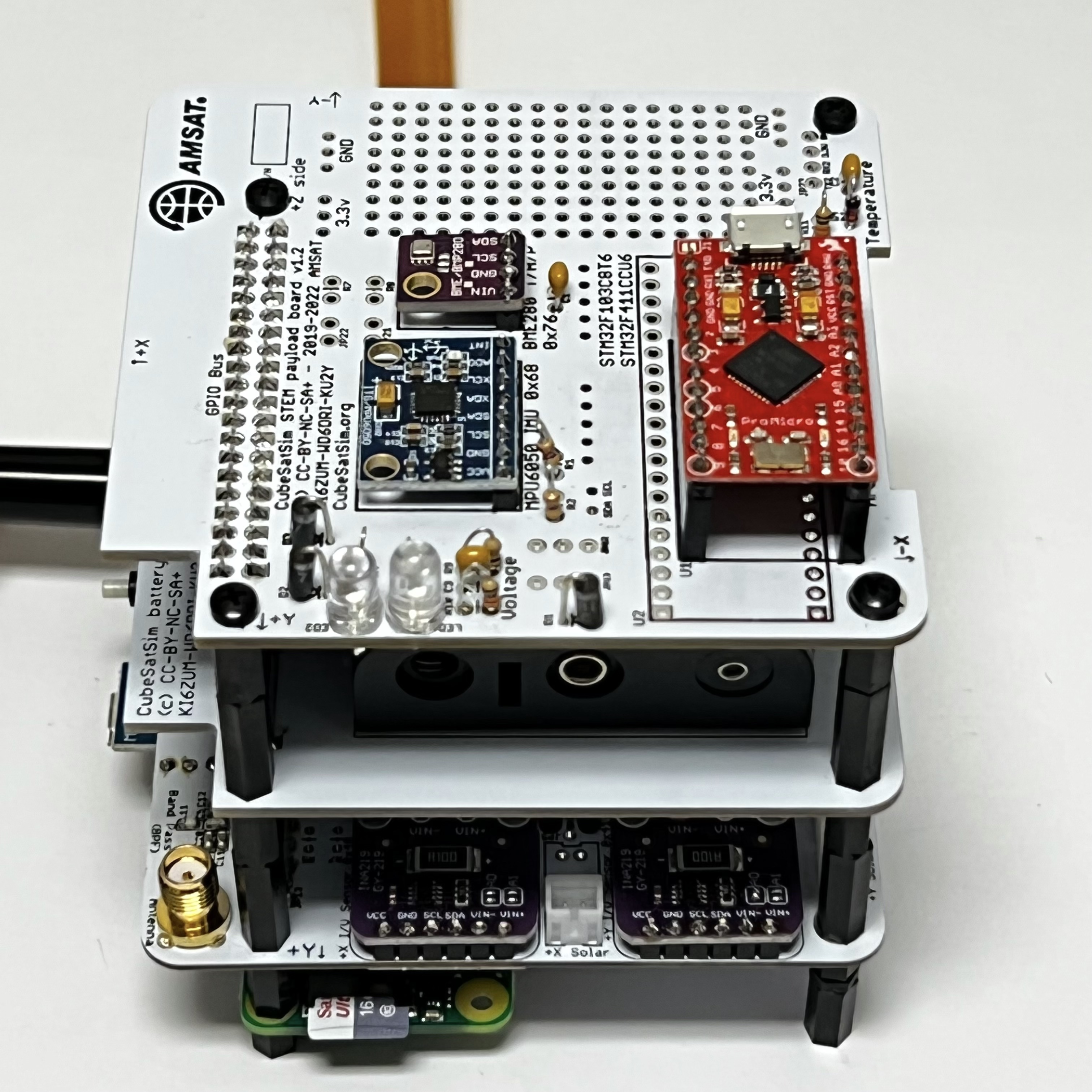
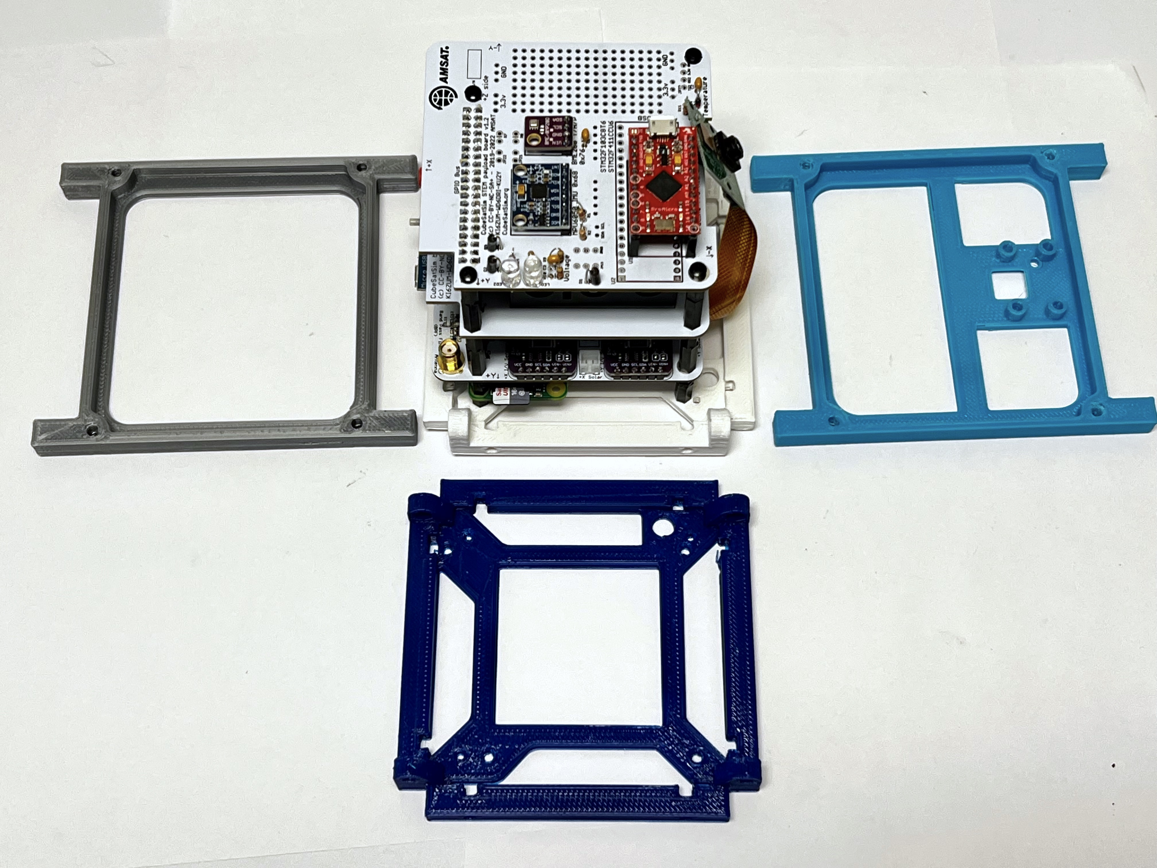
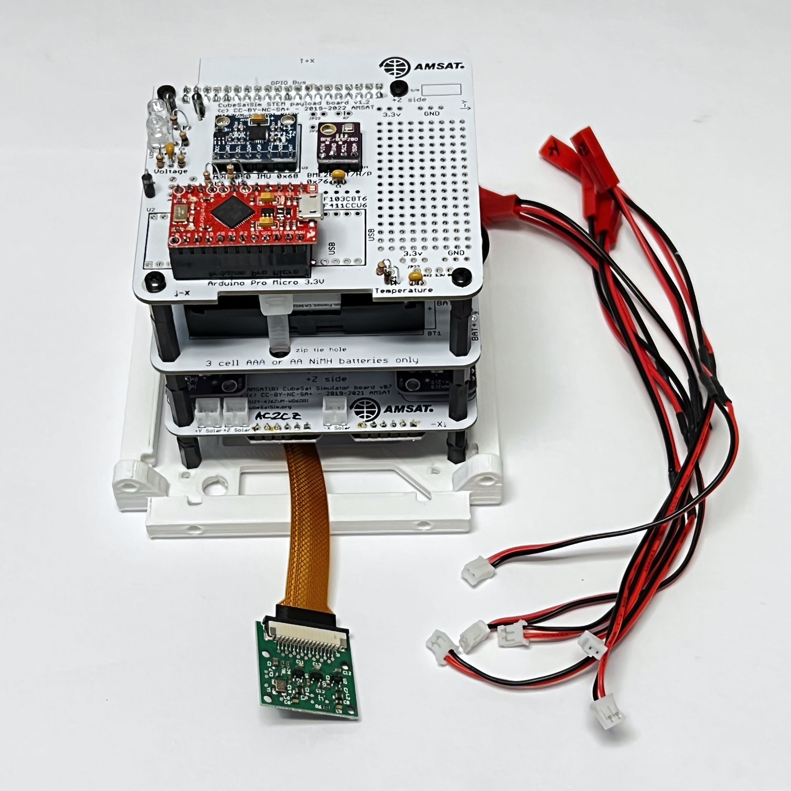
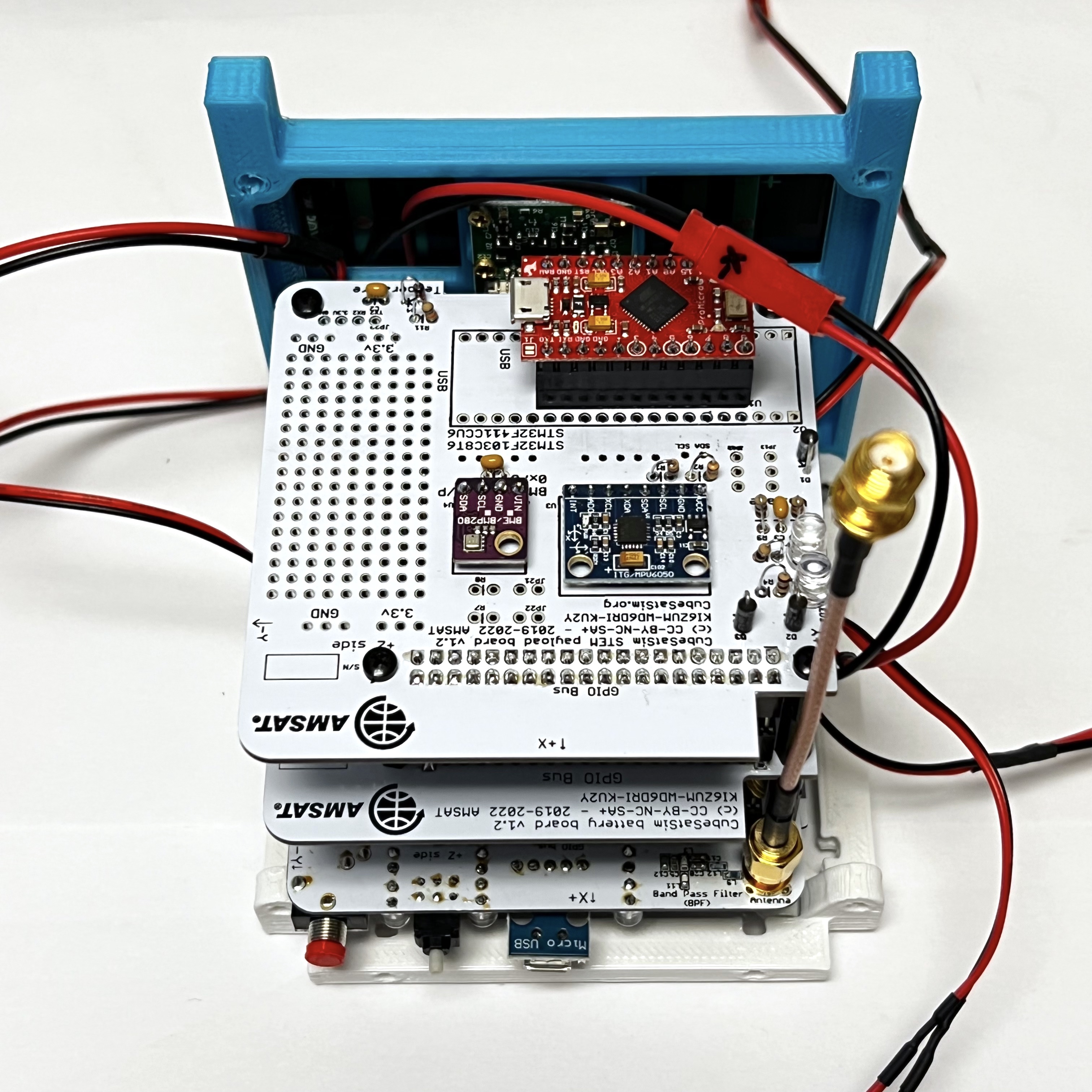
The four boards in the board stack are shown here:
You will need these tools:
- Safety glasses (to protect eyes while soldering or trimming leads)
- Soldering iron and solder (I use lead-free solder, but leaded solder is easier to work with)
- Small Philips screwdriver
- Small flathead screwdriver
- Needle nose pliers (to bend leads and hold parts)
- Side cutters (to trim leads)
- Drill and drill bits, sandpaper or emery cloth (if you are making the dipole or monopole antenna)
Useful to have:
- Liquid flux to solder SMA connector
Video
Here is a video of the antenna install and board stack: https://youtu.be/lyu3lVcrZk4
Checklist
The BOM has a sheet "By Steps" which lists the parts needed for each step in order. http://cubesatsim.org/bom If you have a Google account, you can make a copy of this spreadsheet ("File" then "Make a Copy") and check off each part as you install it.
For example, here is the checklist for this step:
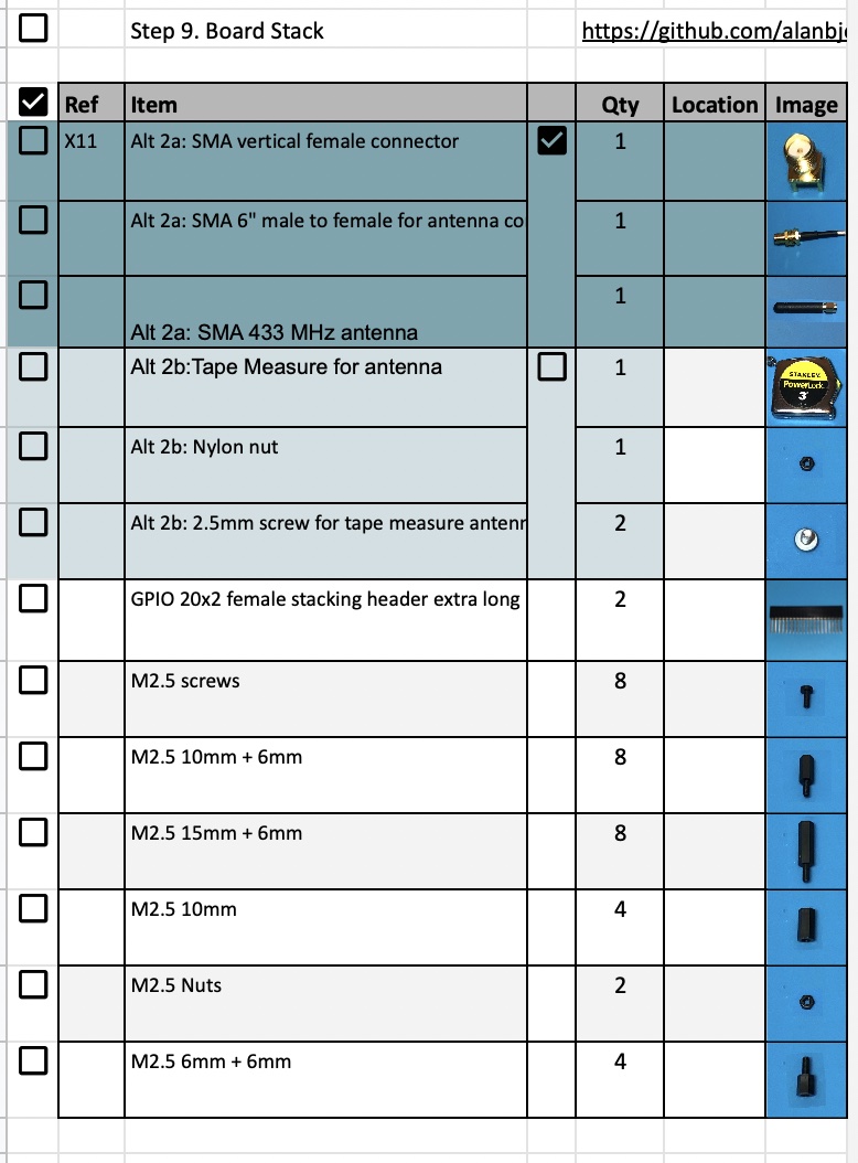
9.1 Antenna Install
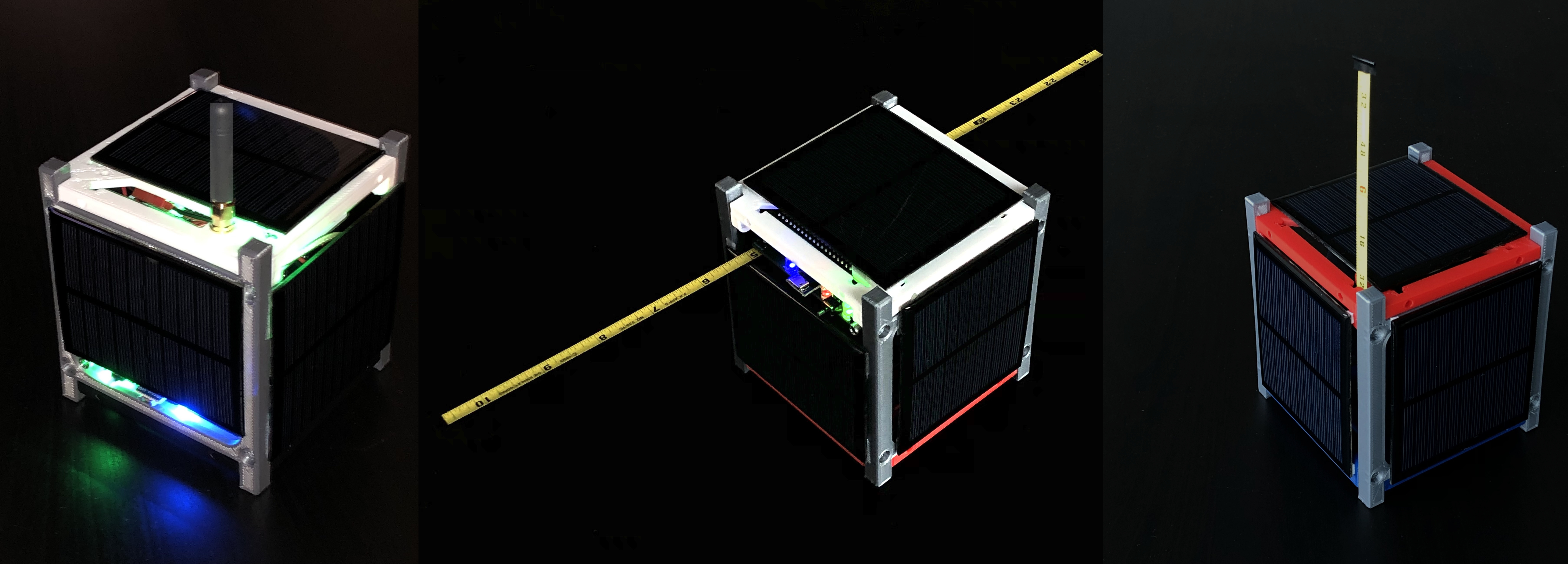
Before we build the board stack, we need to install our antenna. You can build a SMA antenna (left), a tape measure dipole (center), or a tape measure monopole (right) as shown here:
SMA Antenna
To connect an antenna using a SMA connector, you just need to solder an SMA connector onto the top of the Main board. This part takes a lot of heat, so make sure your iron is set to high heat. You might also want to apply liquid flux to the pins to help solder it.
Which gives this:
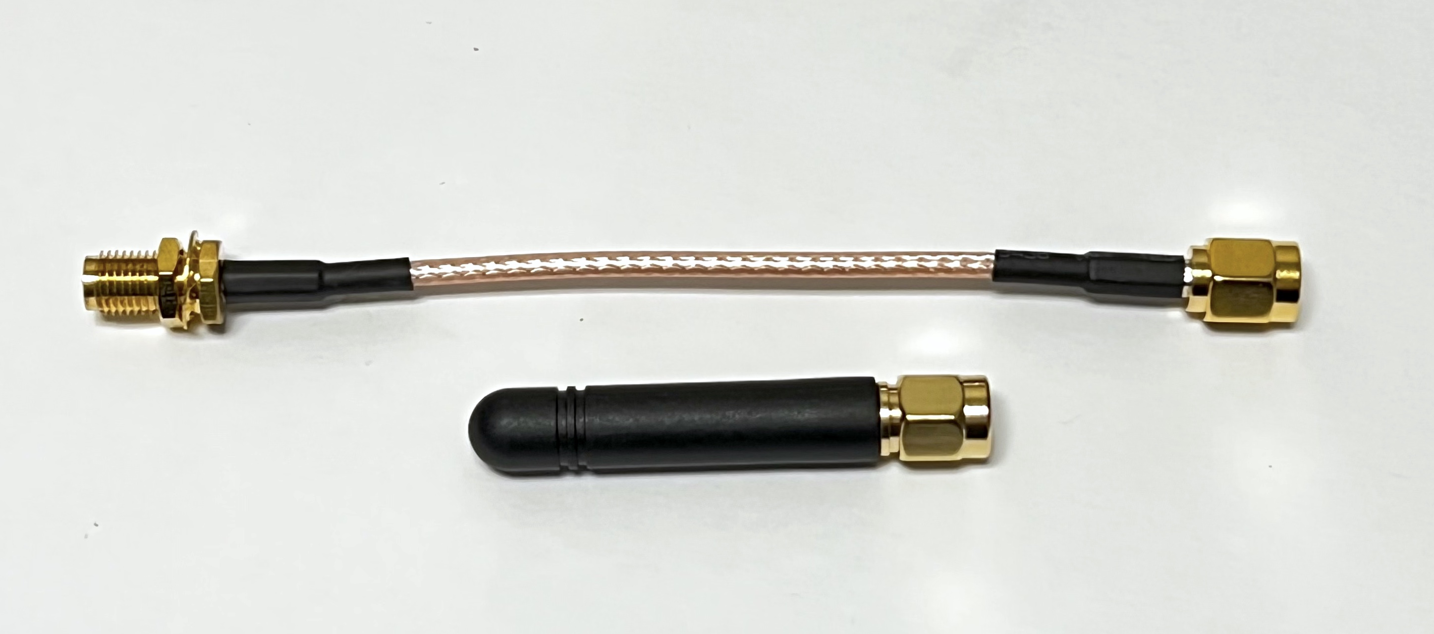
You will connect an SMA coax cable and a rubber duck antenna when you put the frame together.
Tape Measure Dipole Antenna
Alternatively, you can make a tape measure dipole or monopole (vertical) using these parts:
-
1/4" Tape measure (3/8" and larger ones work too)
-
Metal screw, nylon will not make electrical contact
-
Nut, nylon or metal since it is just a spacer
Extend all the tape out of the measure before cutting or the remaining tape will retract inside and you will need to break open the case. Be careful of sharp edges, and put electrical tape over the cut edges immediately.
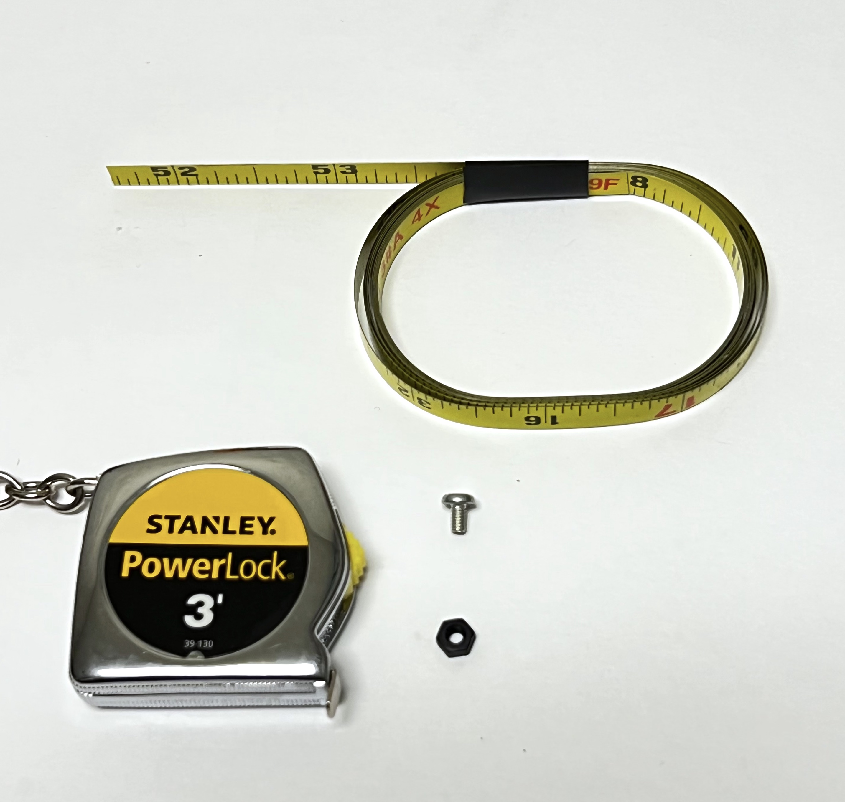
For the dipole antenna, you will need two 1/4 wavelength lengths of tape measure, each with a hole drilled in it. Drilling the hole can be tricky, so drill the hole first, then cut the tape to length. Also, using a punch or small screwdriver to dent the tape in the middle can help prevent the drill from moving around. Also, start with the smallest drill bit you have, ending up with a 3/32" drill bit. It doesn't matter if the hole is slightly off center. Using sand paper or emery cloth, remove the paint from the tape around the hole on the bottom (no numbers) side of the tape measure. Cut to length after you have successfully made the holes, approximately 6.5 inches:
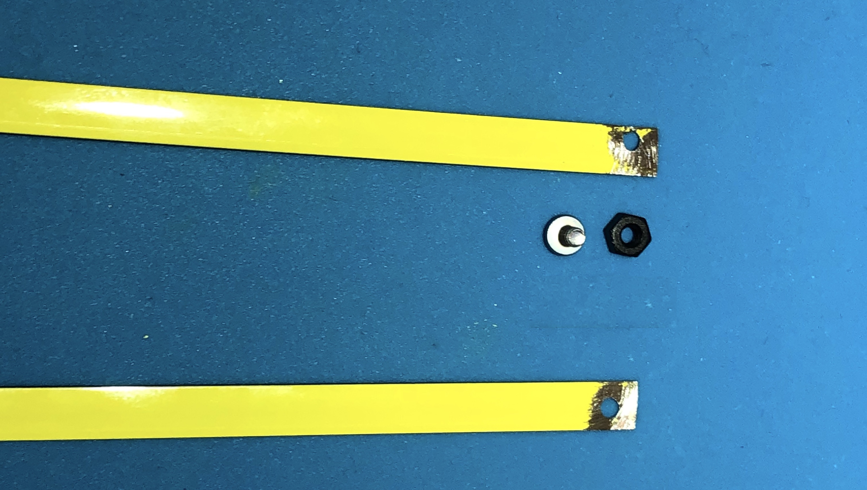
Screw the nut onto the screw, the put the screw through the hole in one of the tape lengths. The screw will cut threads into the center hole of the antenna connector as shown. It can be easier to start the screw in the hole without the tape measure at first to begin cutting the threads.
The other tape length is held in place by the nylon spacers. You will attach the tape measure antenna just before you plug in the battery board, using the spacer to hold it in place.
The details of how to install the spacers are described below in the Stacking the Boards section.
Tape Measure Monopole Antenna
To build the monopole, you only need to cut one length of tape measure to the same length as the dipole, approximately 6.5 inches long. You need to bend the tape measure next to the hole to a right angle, but don't fold it as it will break off

Screw the screw into the board so the monopole antenna goes vertical. There will be a slot in the top frame piece for the tape measure to stick out.
9.2 Stacking the Boards
In order to stack the boards, we will need a set of 2.5mm nylon spacers and two GPIO stacking headers.
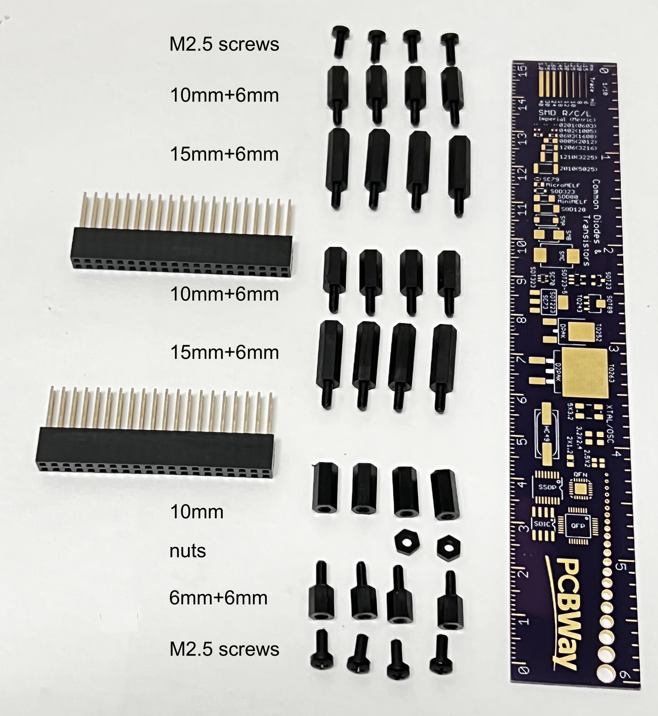
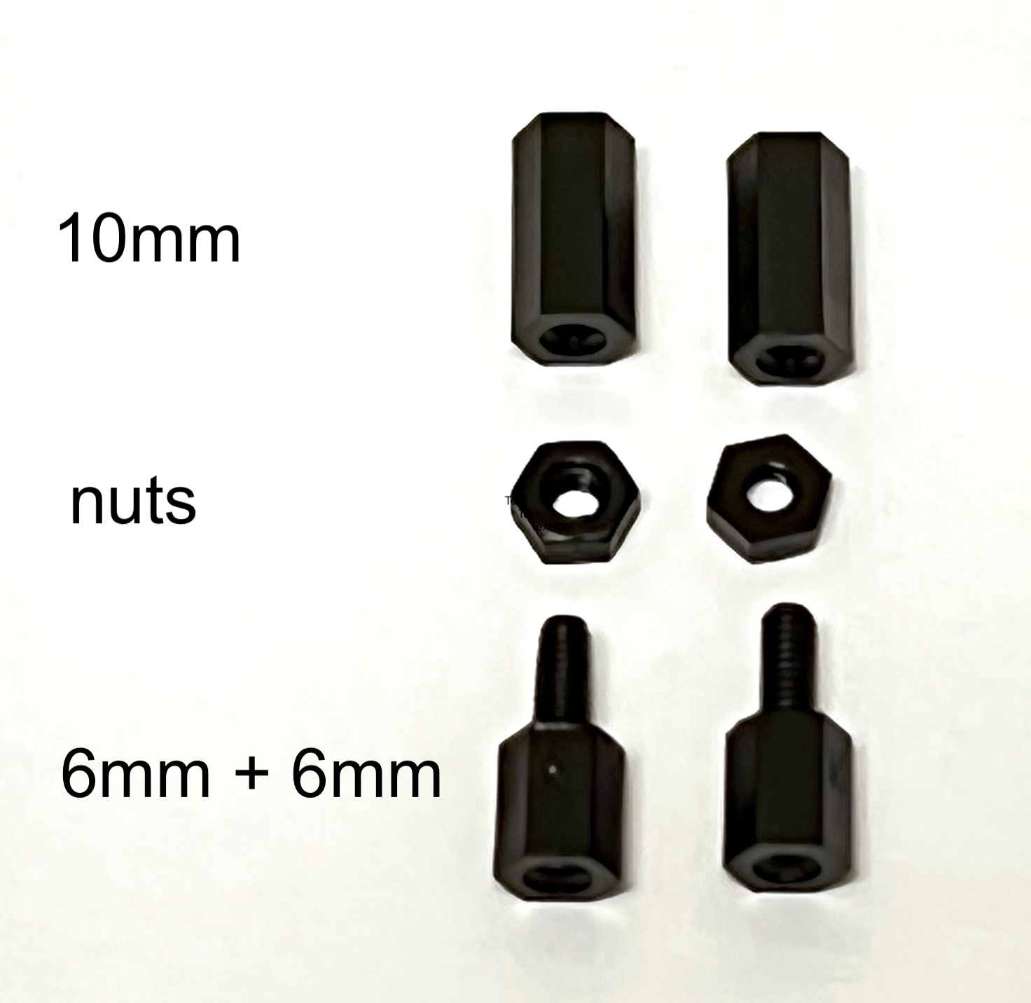
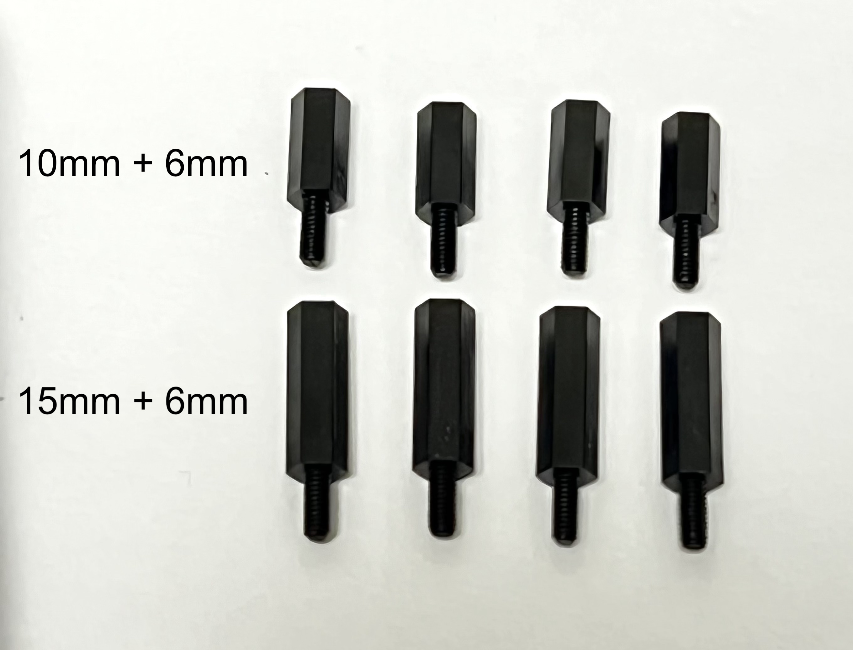
Standoffs are described by the thread size (M2.5 in this case), length of the standoff (6, 10, and 15mm), and length of the standoff threads if any (+6mm). Also M2.5 screws and nuts are used. Here are the standoff pieces needed for the three board stack along with their names in their correct order and orientation if you mounted your INA219 purple boards using sockets:
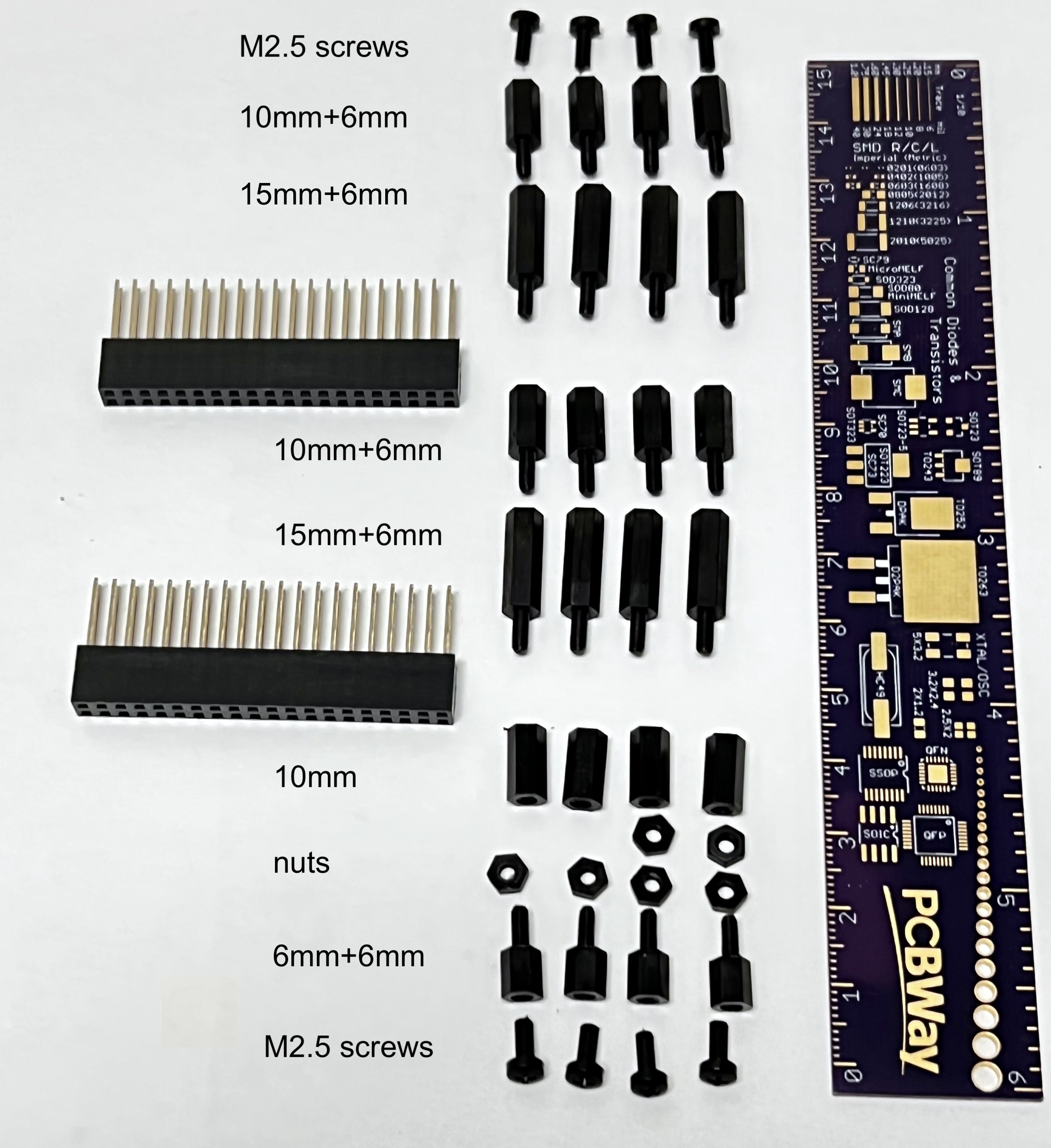
If you soldered them in, use one less nut on the bottom:
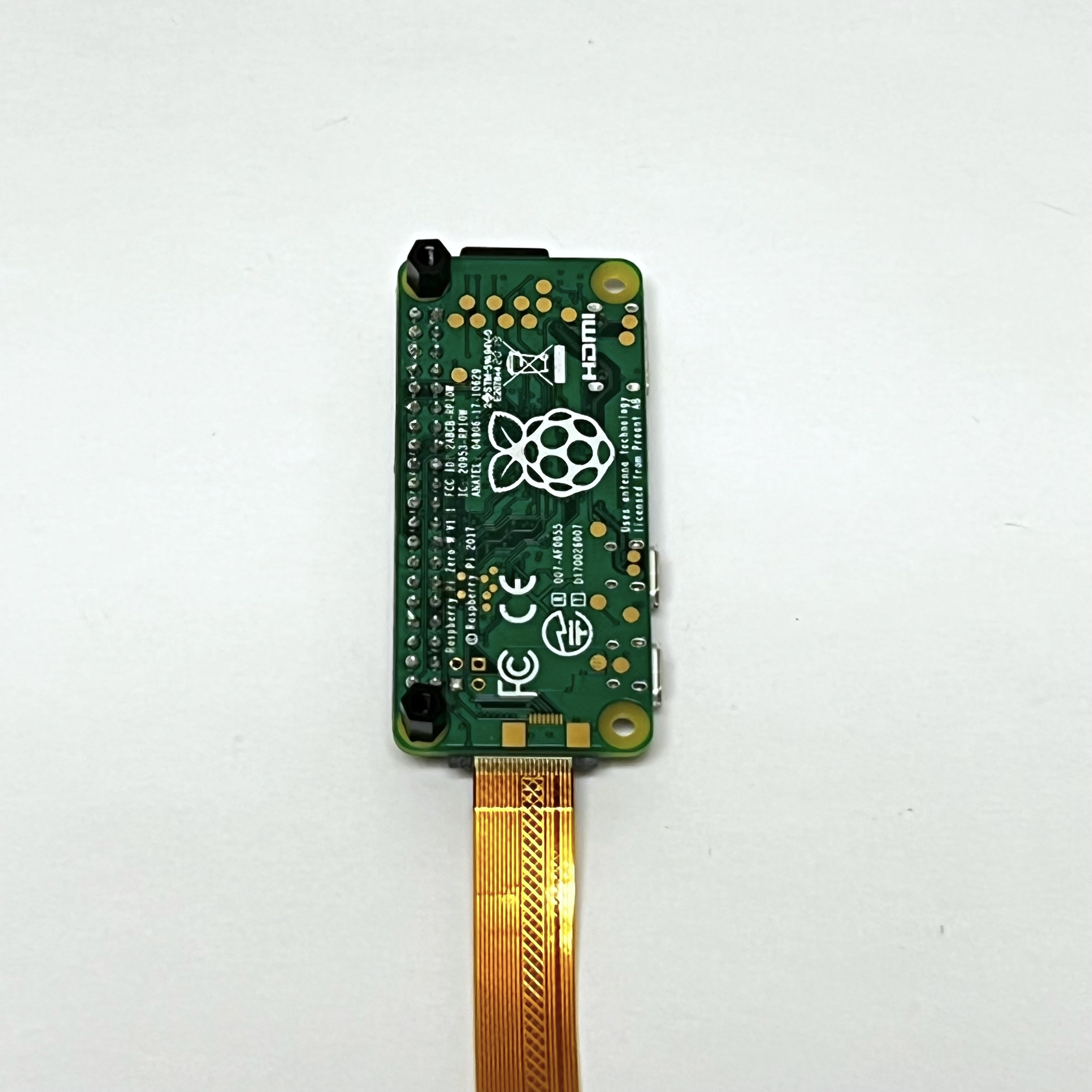
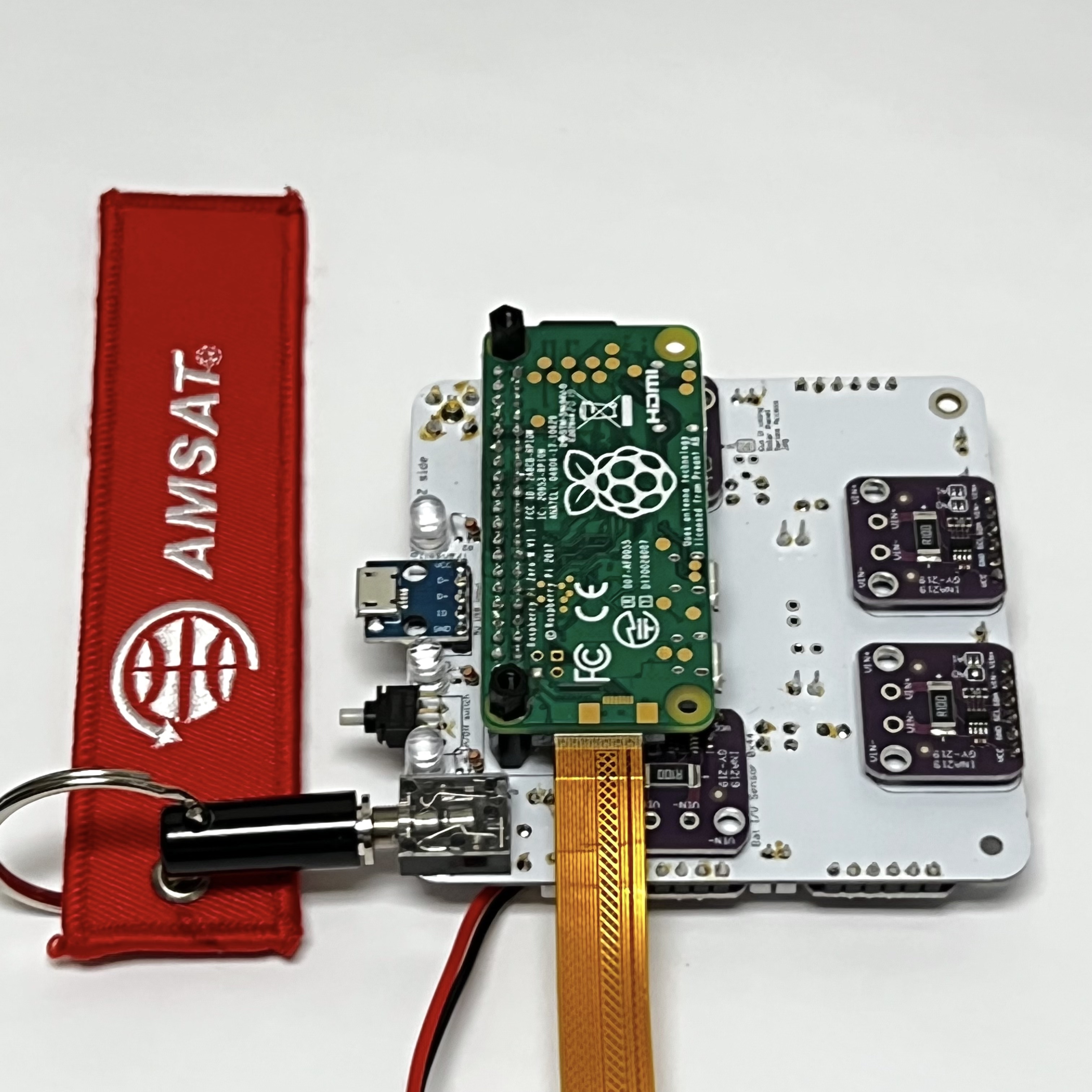
Start by adding standoffs to the bottom of the Pi Zero W board next to the GPIO header (2x M2.5 6mm+6mm). If you are using the Pi Camera, your Pi Camera should already be connected using the cable to the Pi Zero WH. As you build the board stack, be very careful not to pull out or pinch the camera cable.
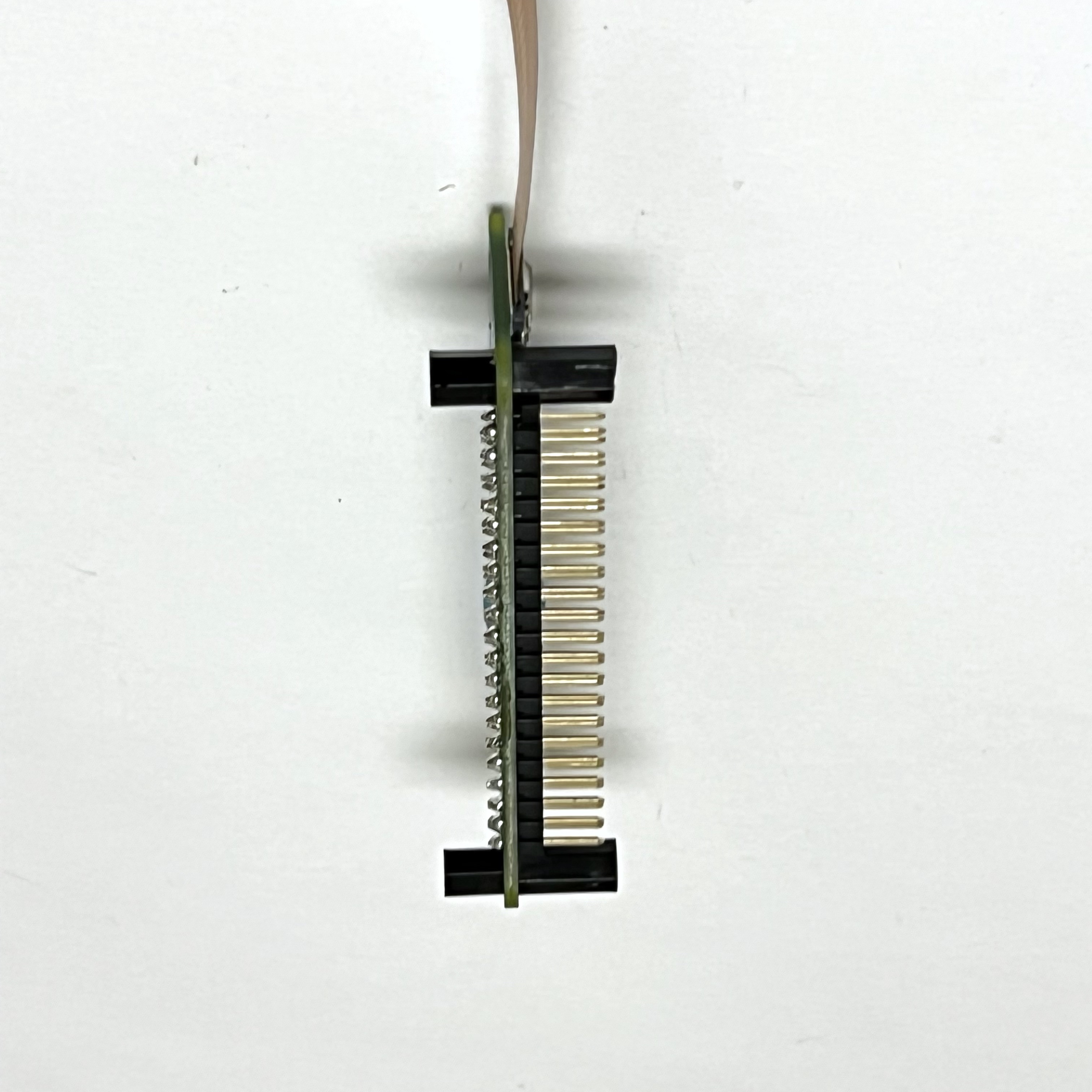
Next, add spacers to the top of the Pi Zero W board next to the GPIO header (2x M2.5 10mm):
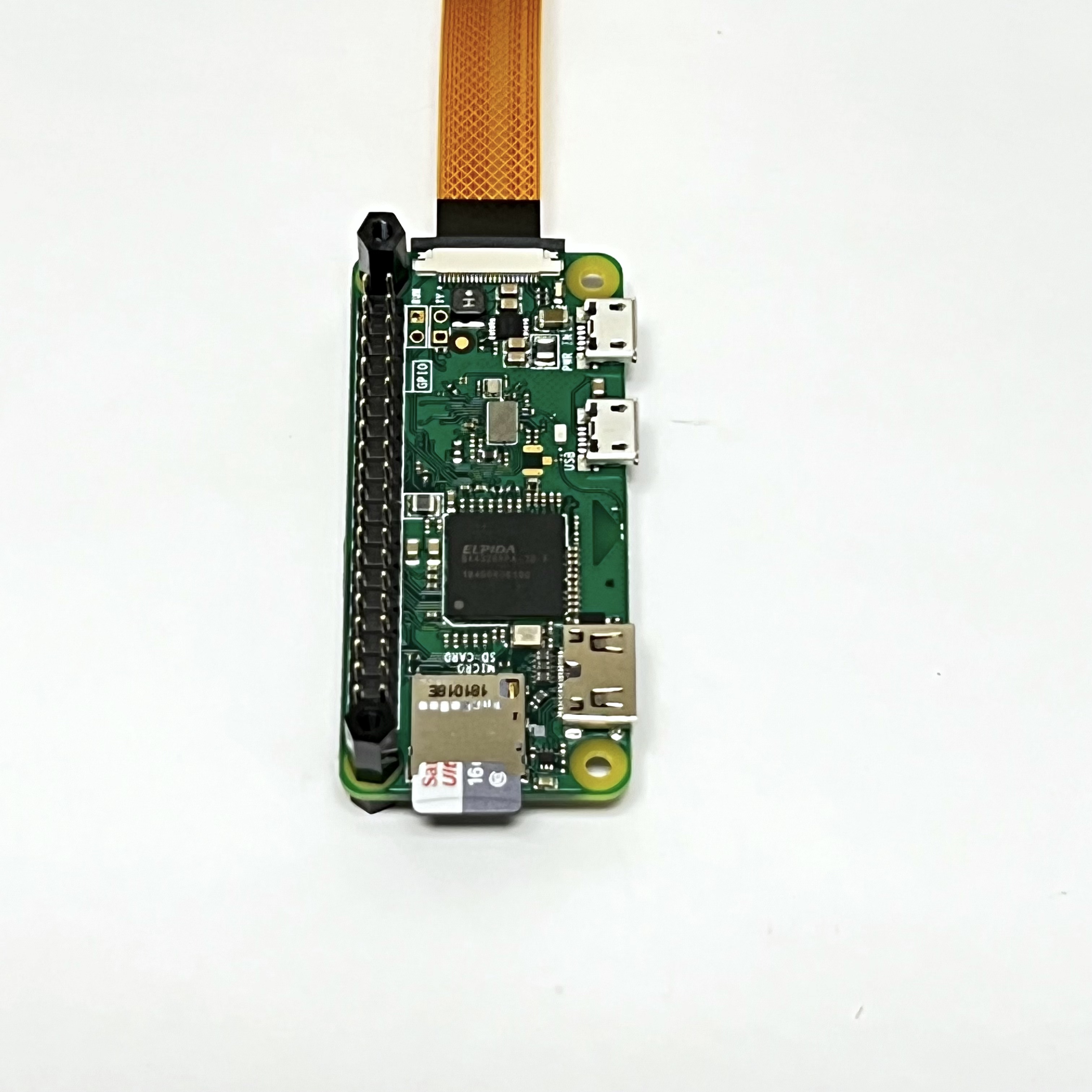
Here's how it looks from another angle:
Now, plug the Pi Zero W into the bottom of the Main board.
Make two of these standoff stacks with a M2.5 6mm+6mm spacer, a nut, and a M2.5 10mm spacer in this order:
Flip the Main board right side up and put each spacer stack under the other two holes in the Main board:
Plug a stacking GPIO header into the board to give the necessary spacing:
Create four of these spacer stacks using a M2.5 15mm+6mm and a M2.5 10mm+6mm spacer.
Insert the threaded end of each spacer stack through one of the holes, screwing it into the spacer underneath. If you built the dipole antenna, now is when you place the tape measure length over the hole in the PCB.
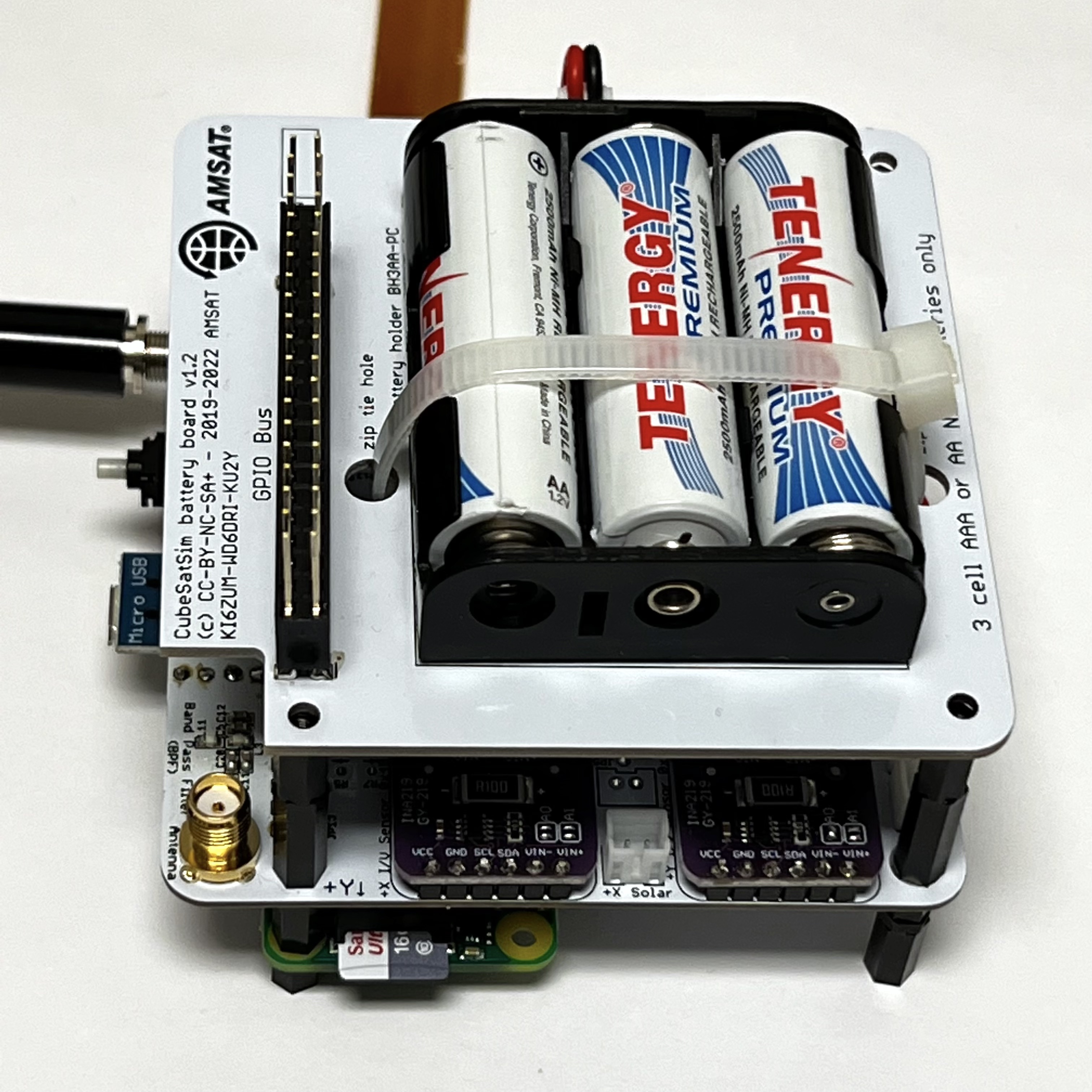
Make sure the Remove Before Flight (RBF) pin is inserted. This will ensure that the Pi will not power up before you are ready. Plug in the JST 2.0 connector from the Battery Board into the Main Board then plug the Battery board on top.
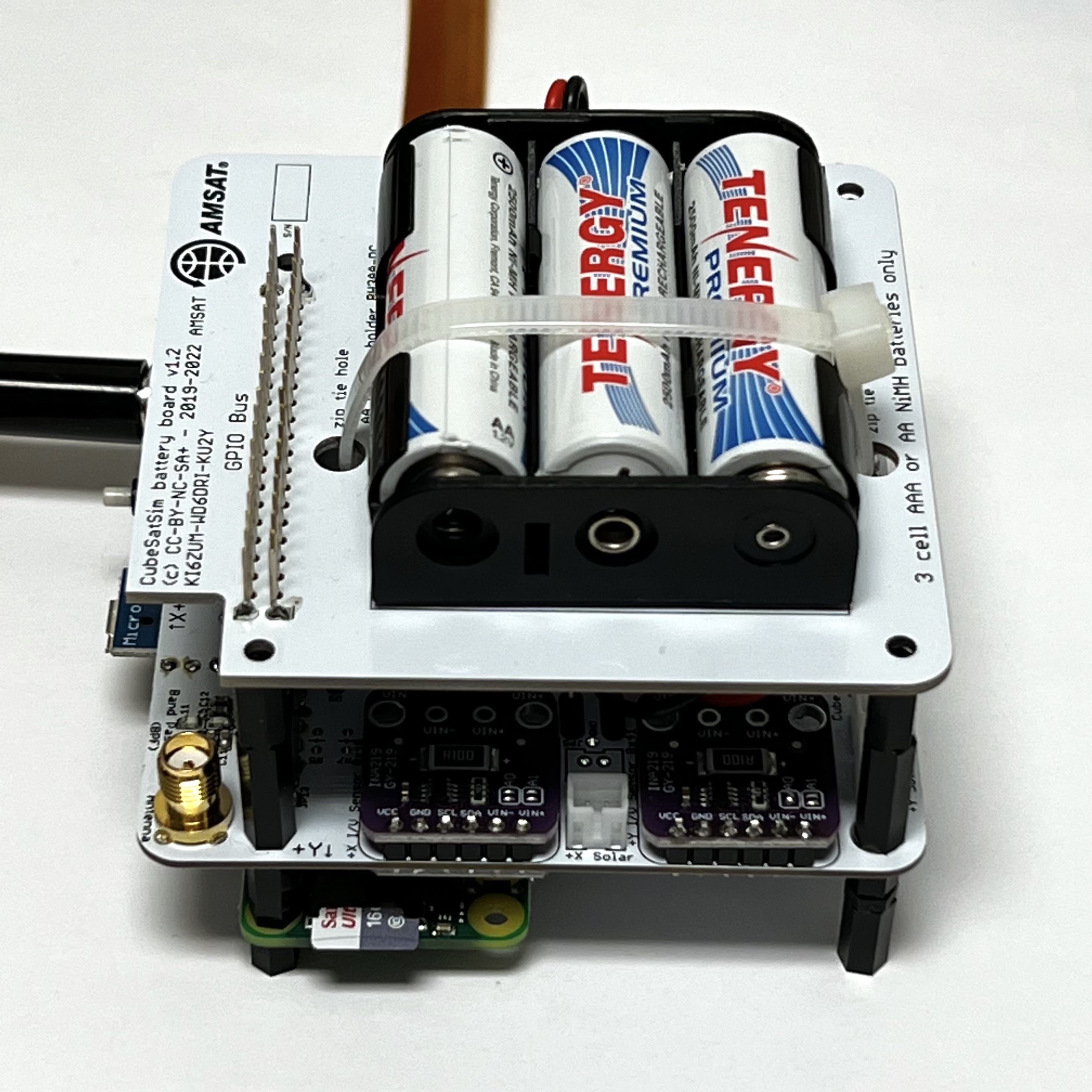
Here is how it looks from another angle:
Plug another stacking GPIO header into the Battery board to give the necessary clearance:
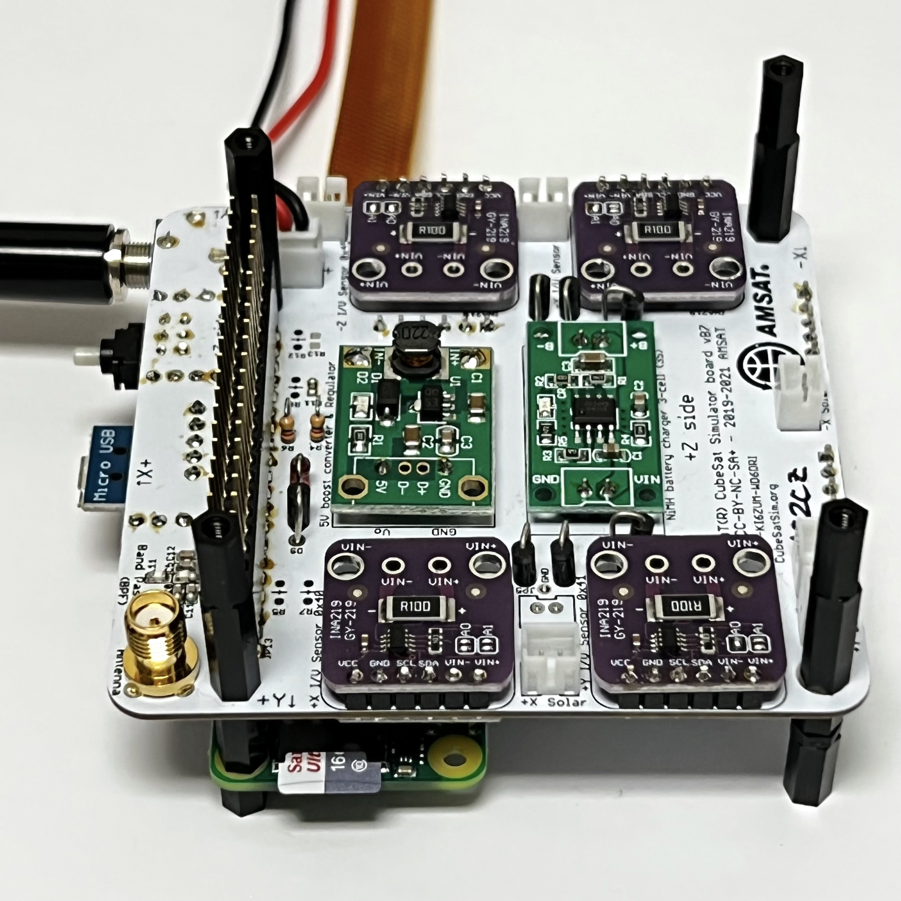
Now create four more of the standoff stacks with the M2.5 15mm+6mm and M2.5 10mm+6mm spacers and insert the threaded end into the holes on the Battery board:
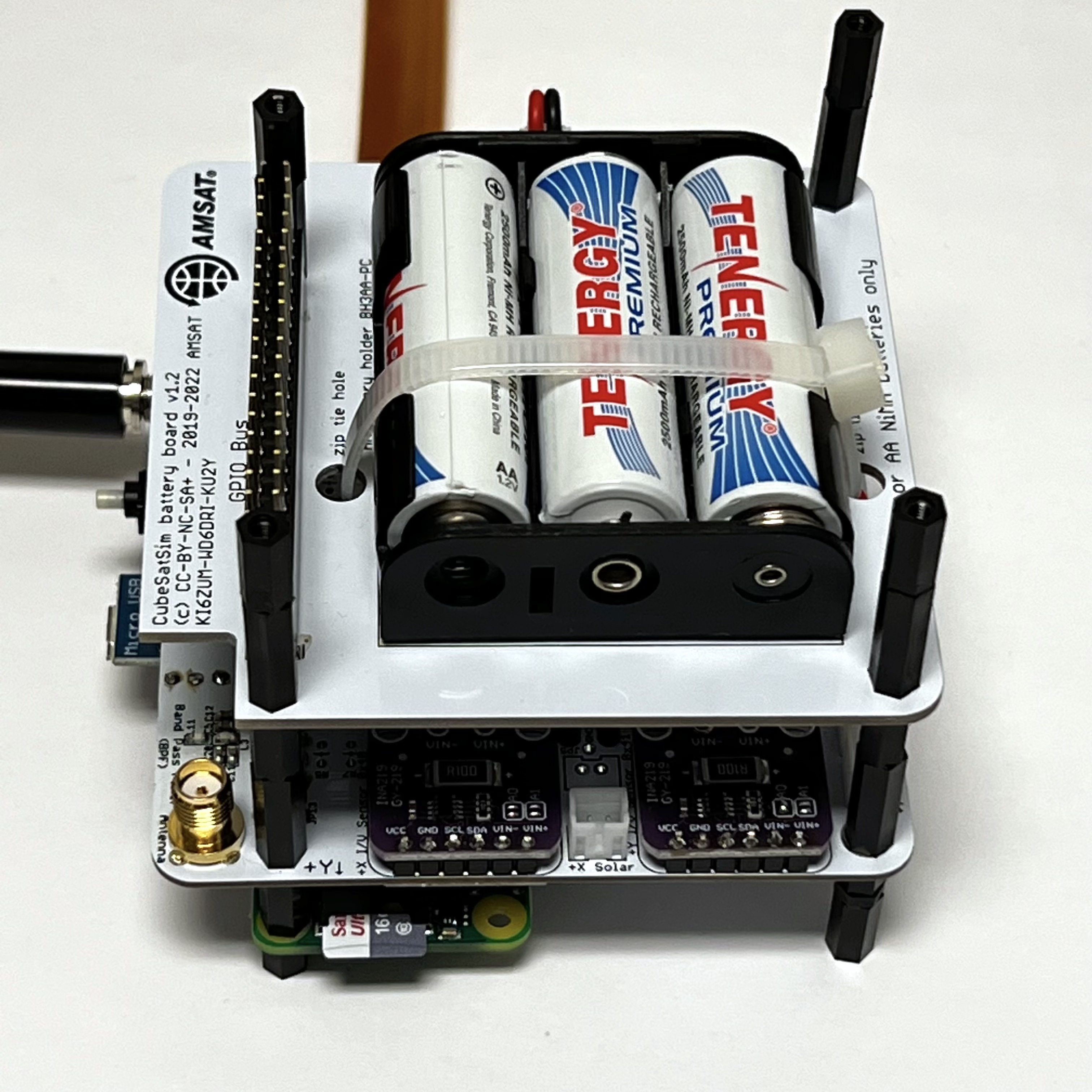
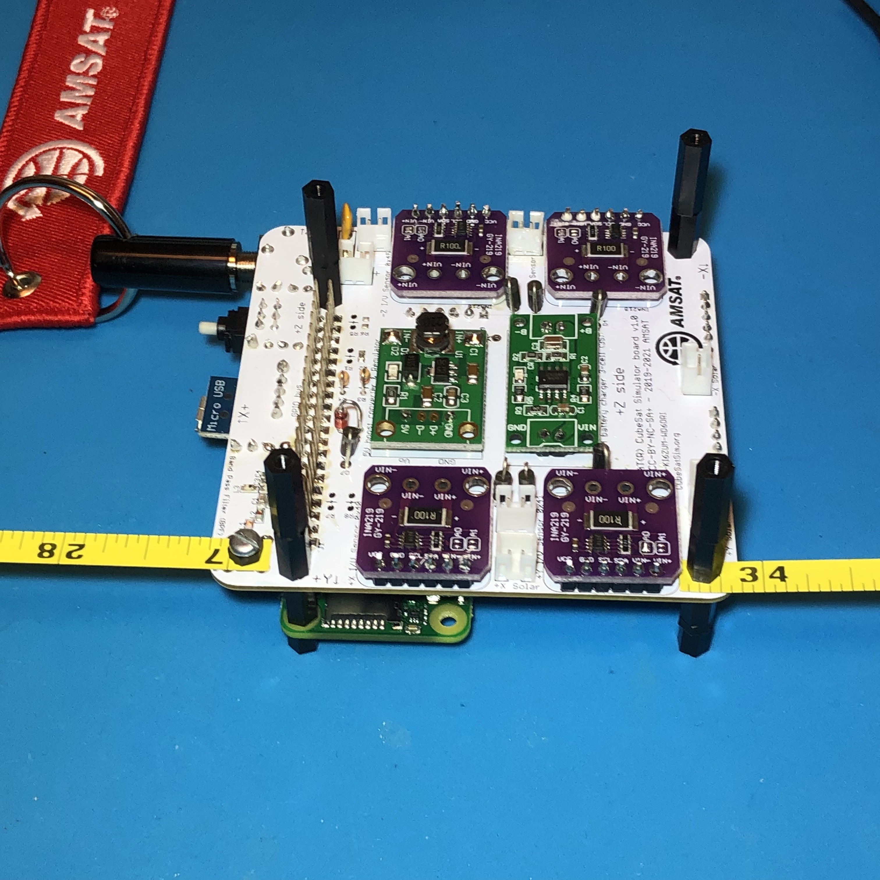
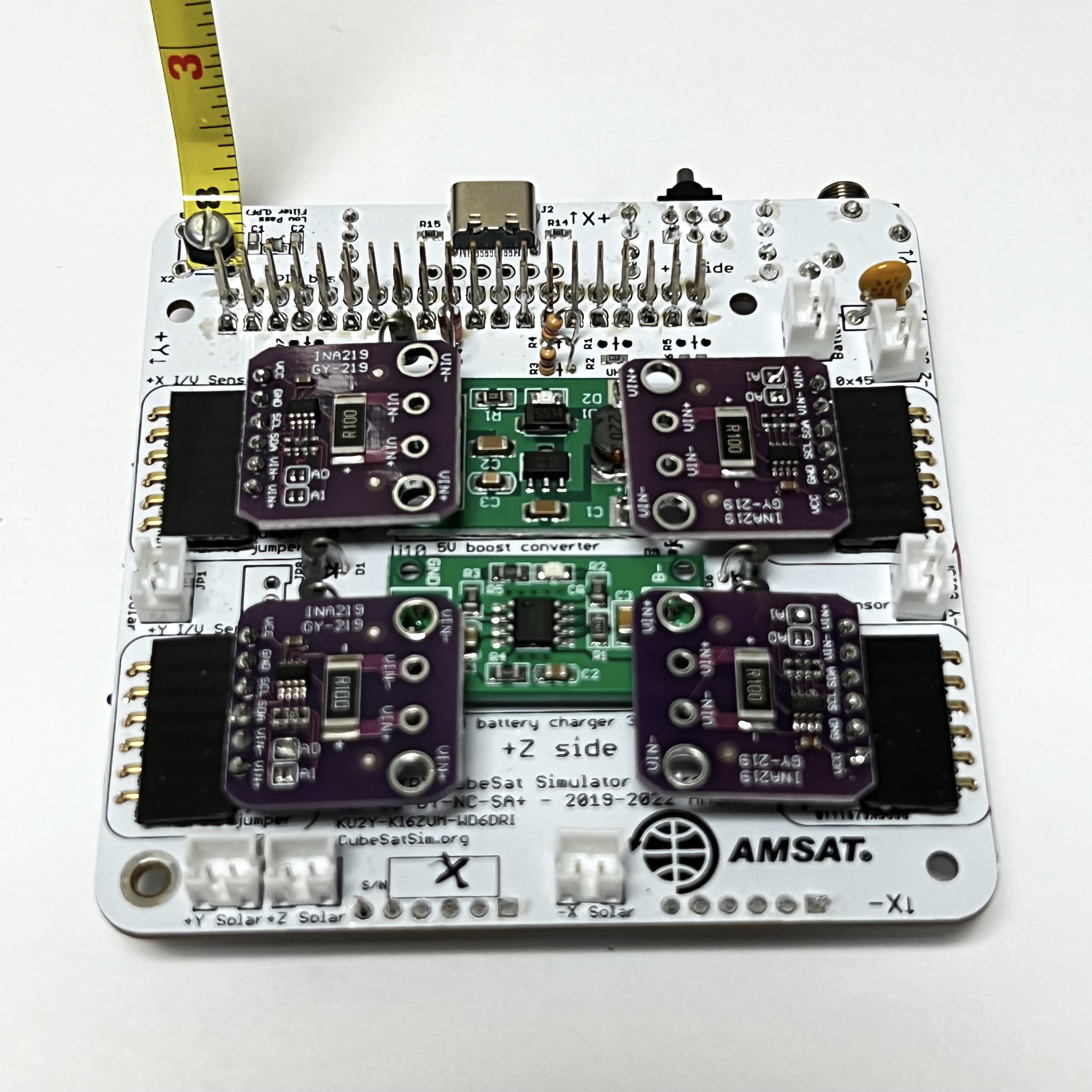
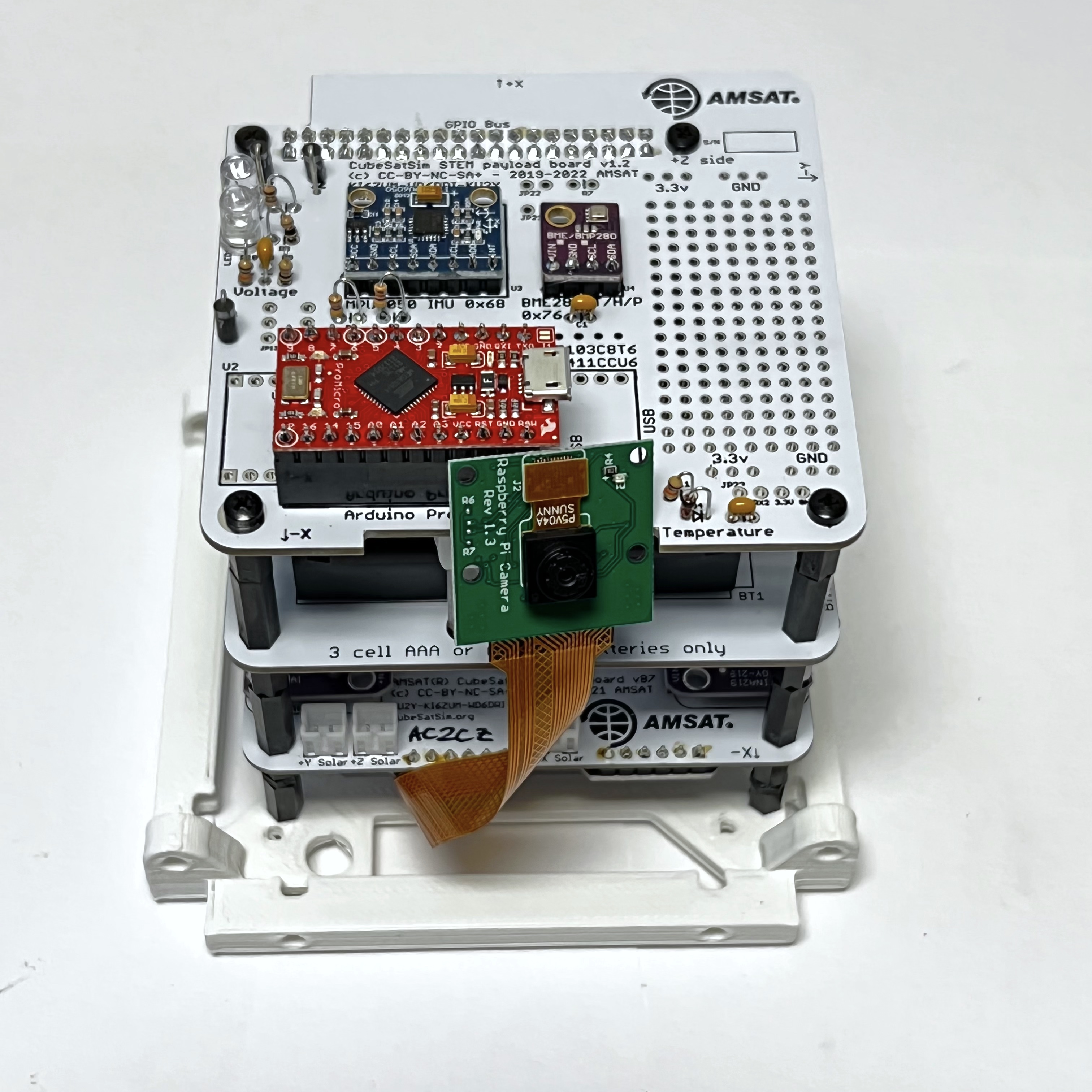
Plug the STEM Payload Board on top:
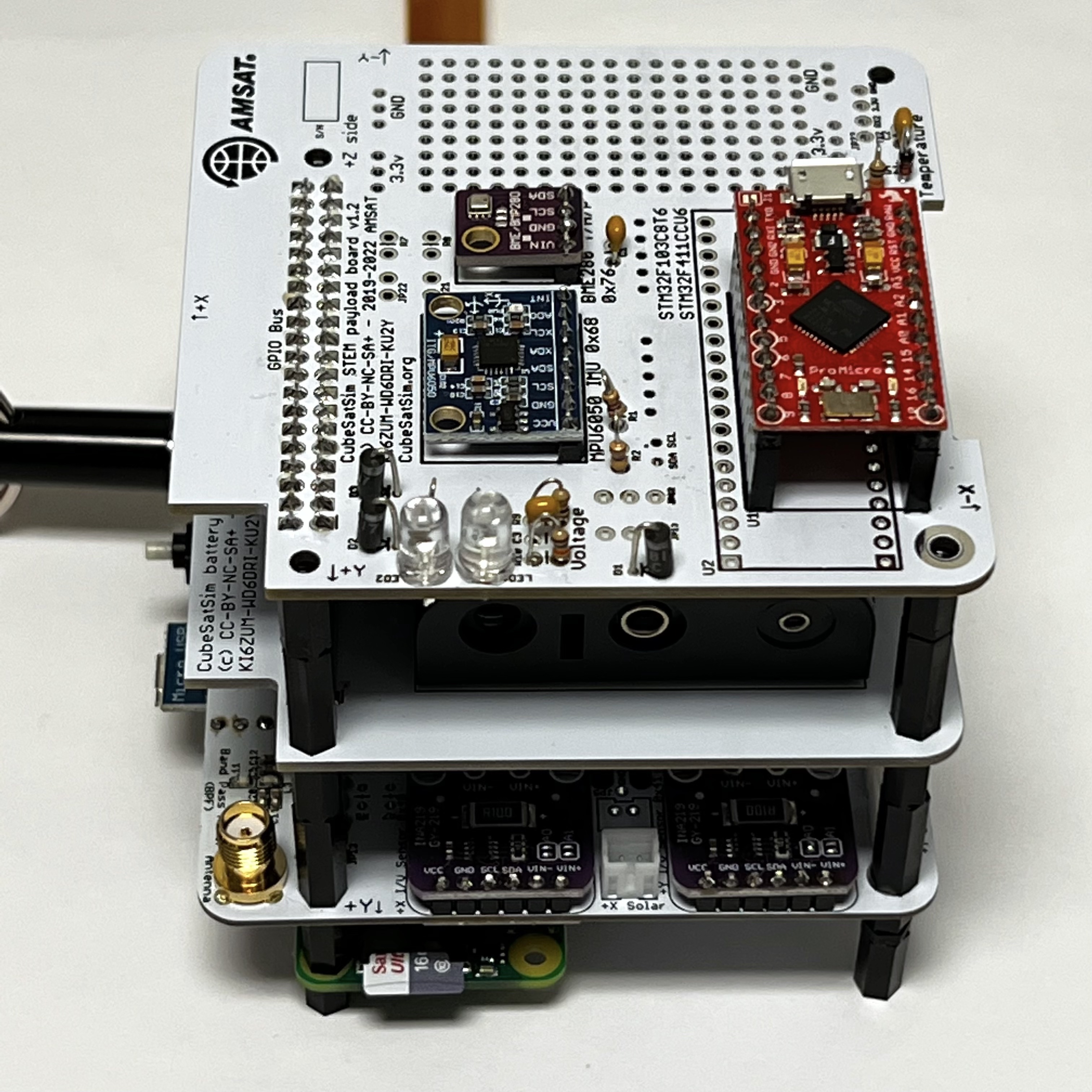
Secure with four screws (4x M2.5 screws):
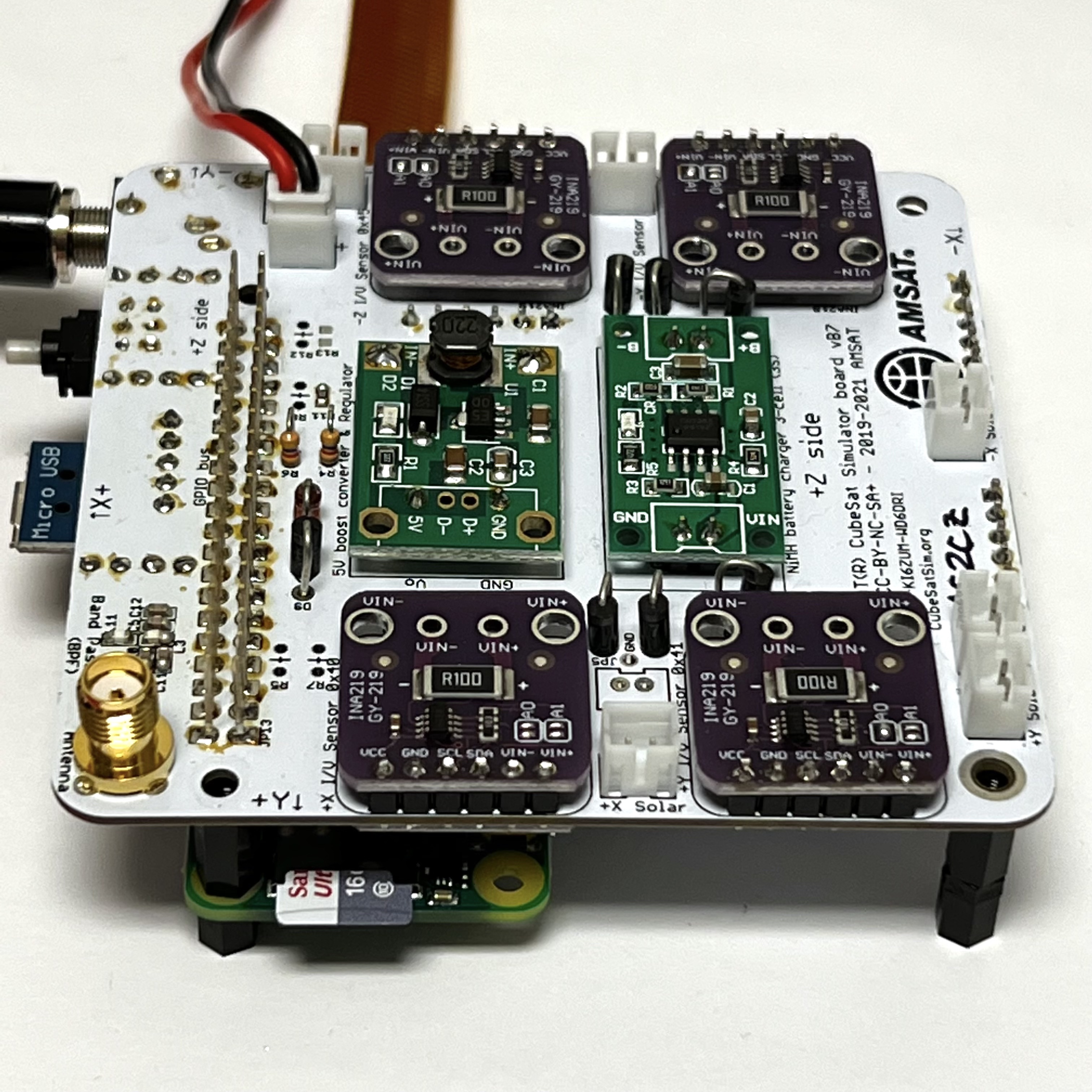
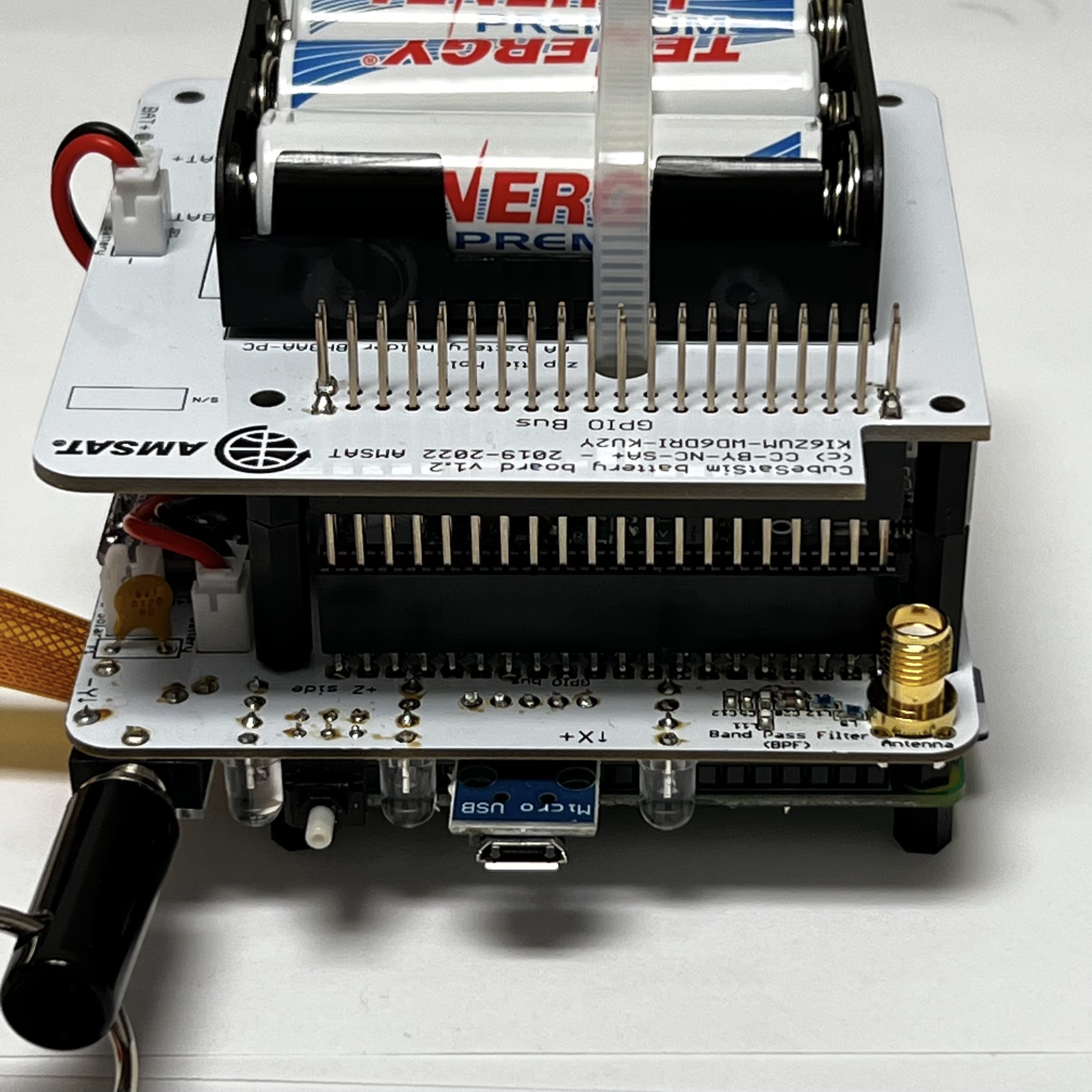
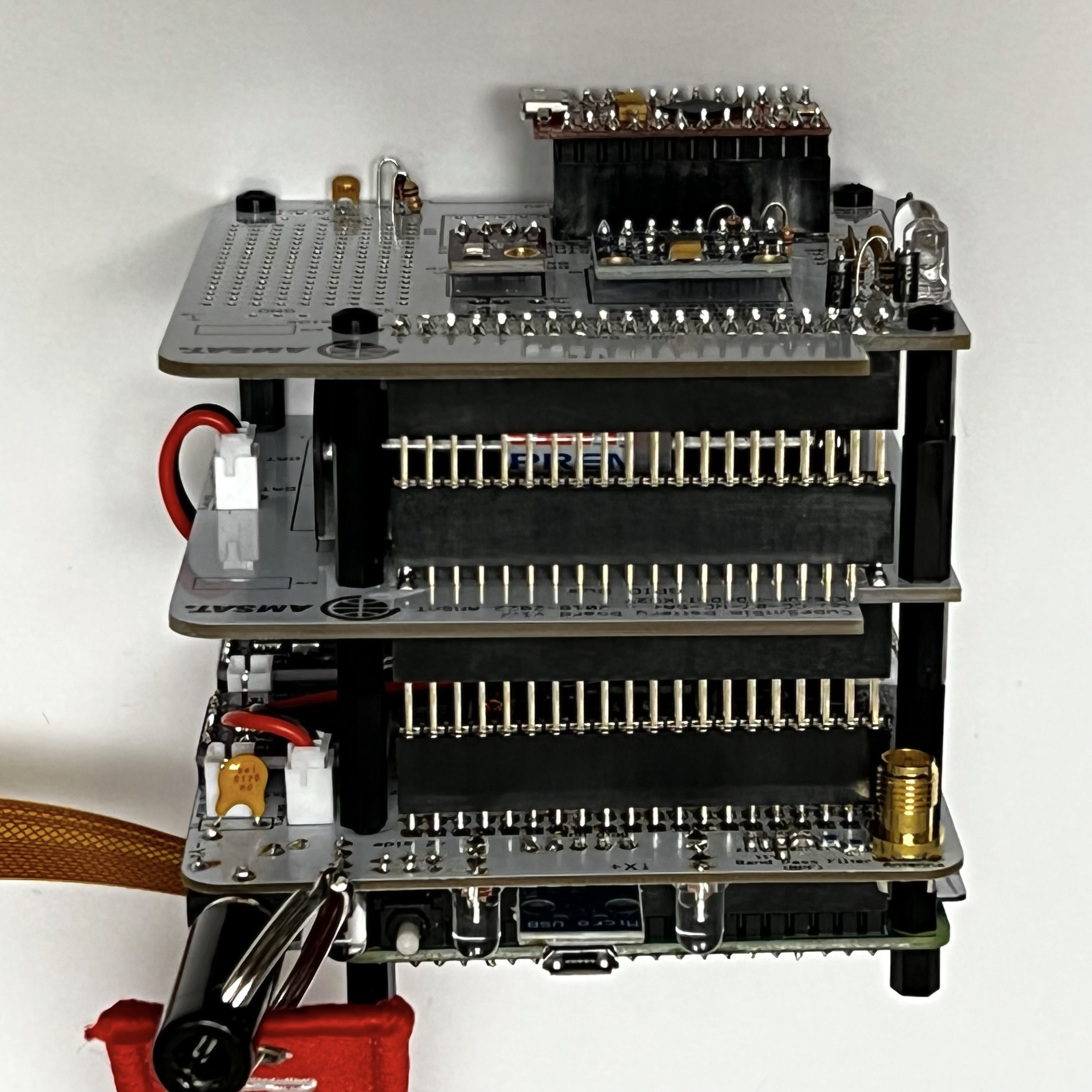
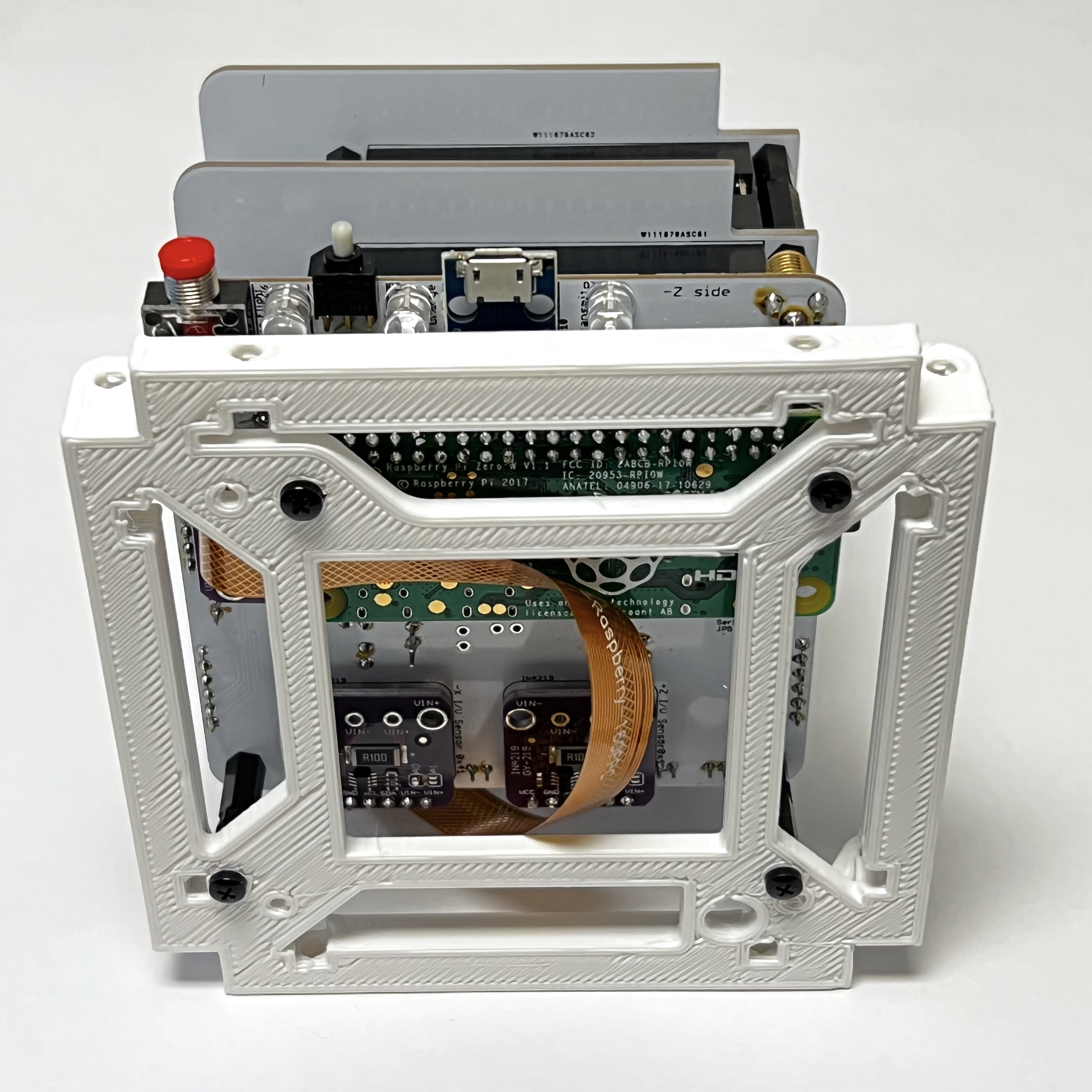
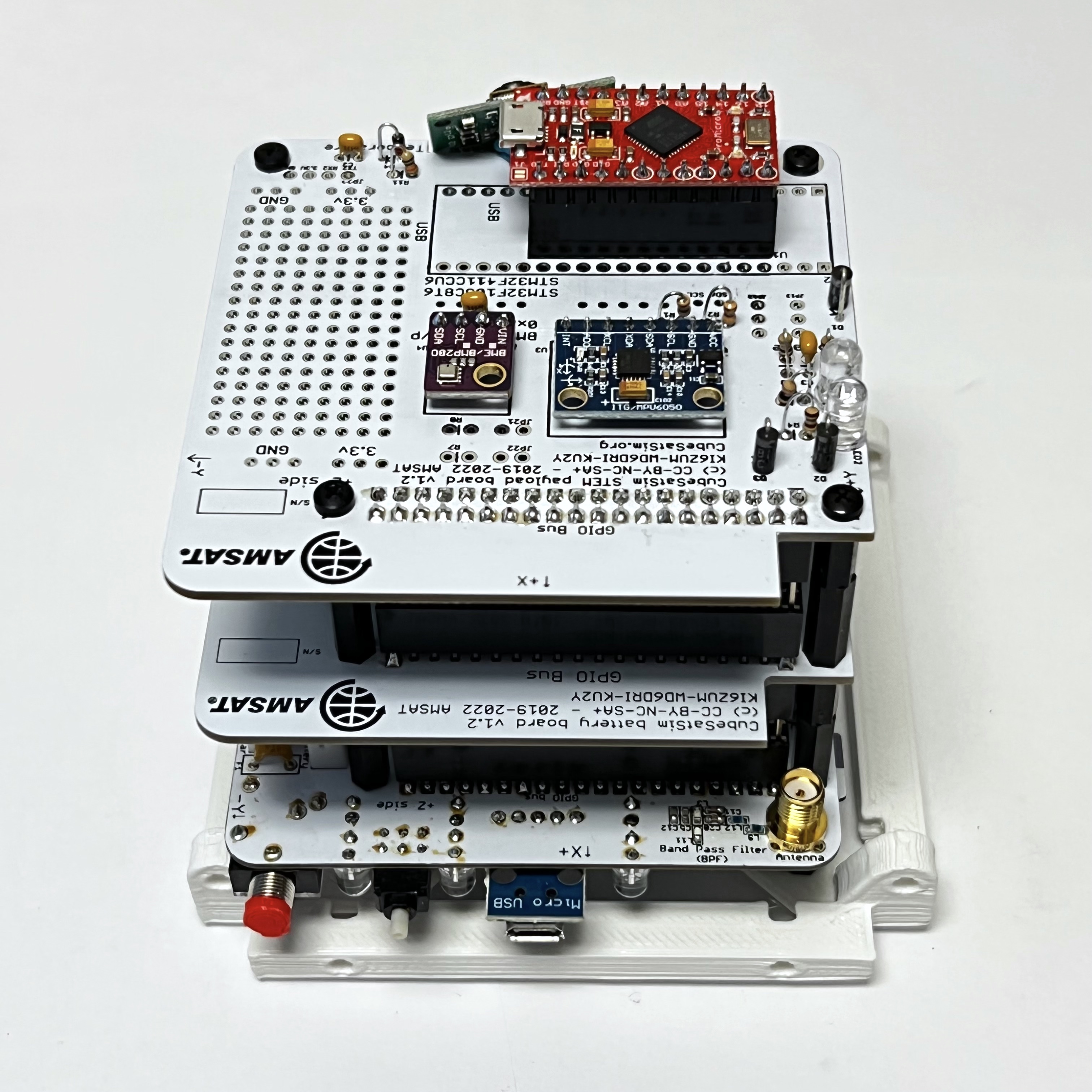
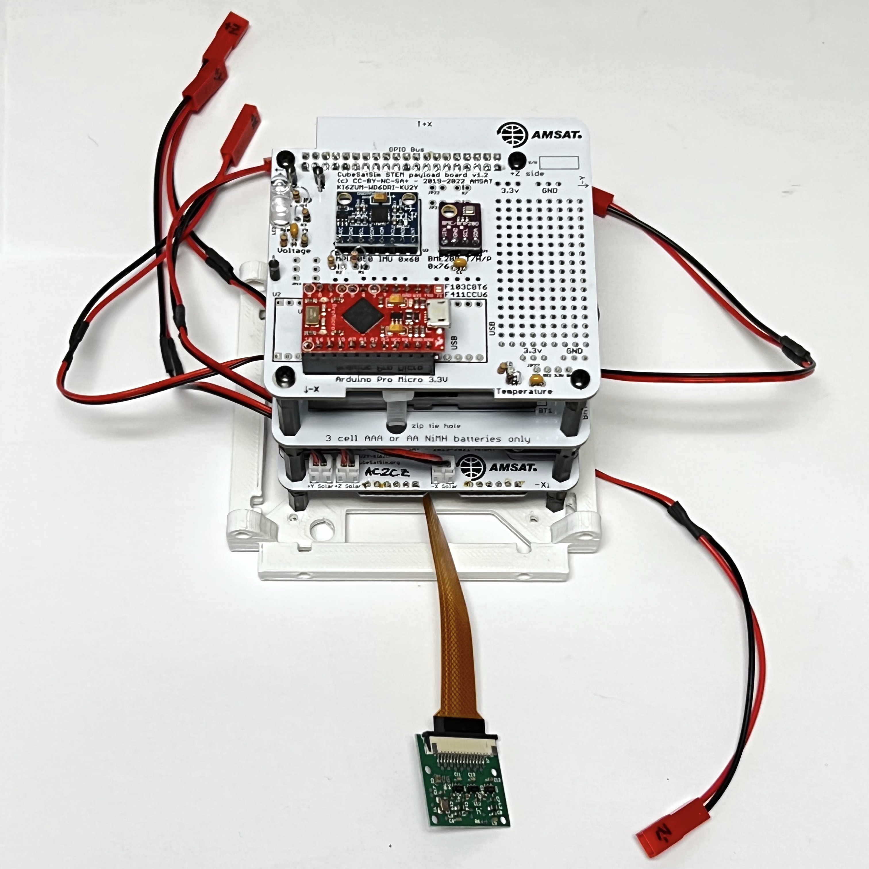
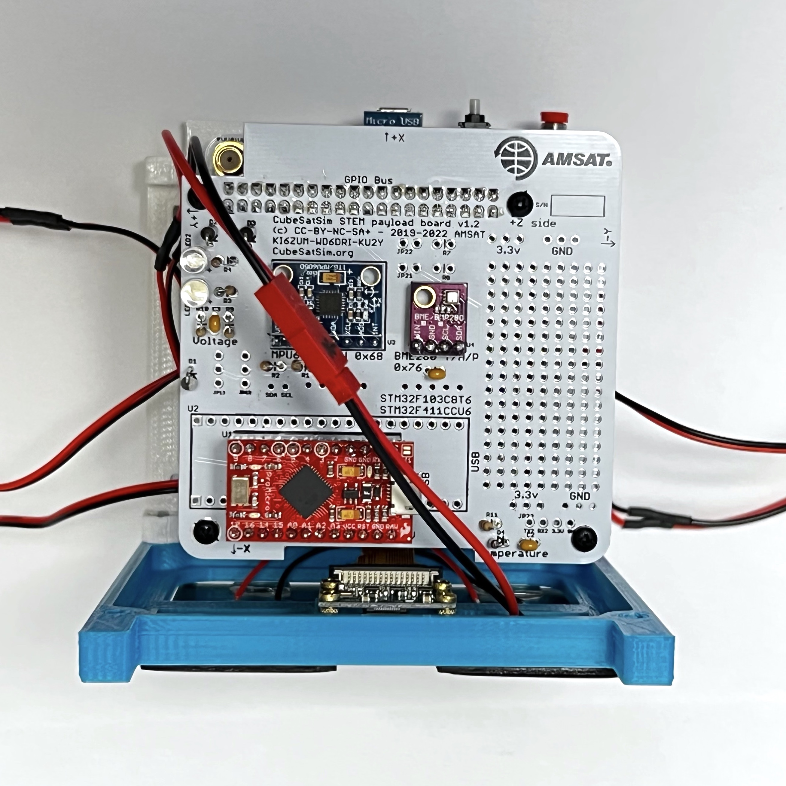
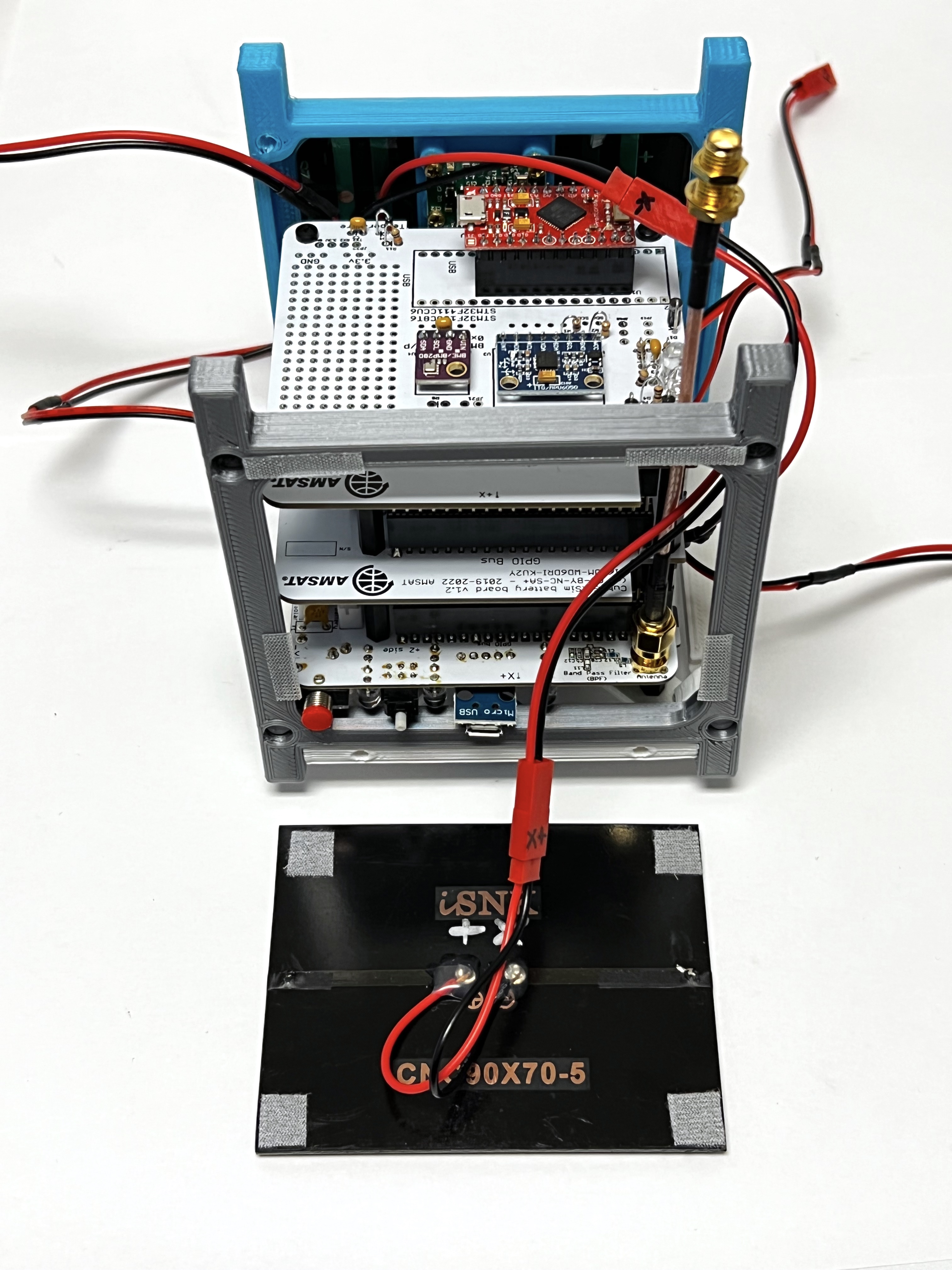
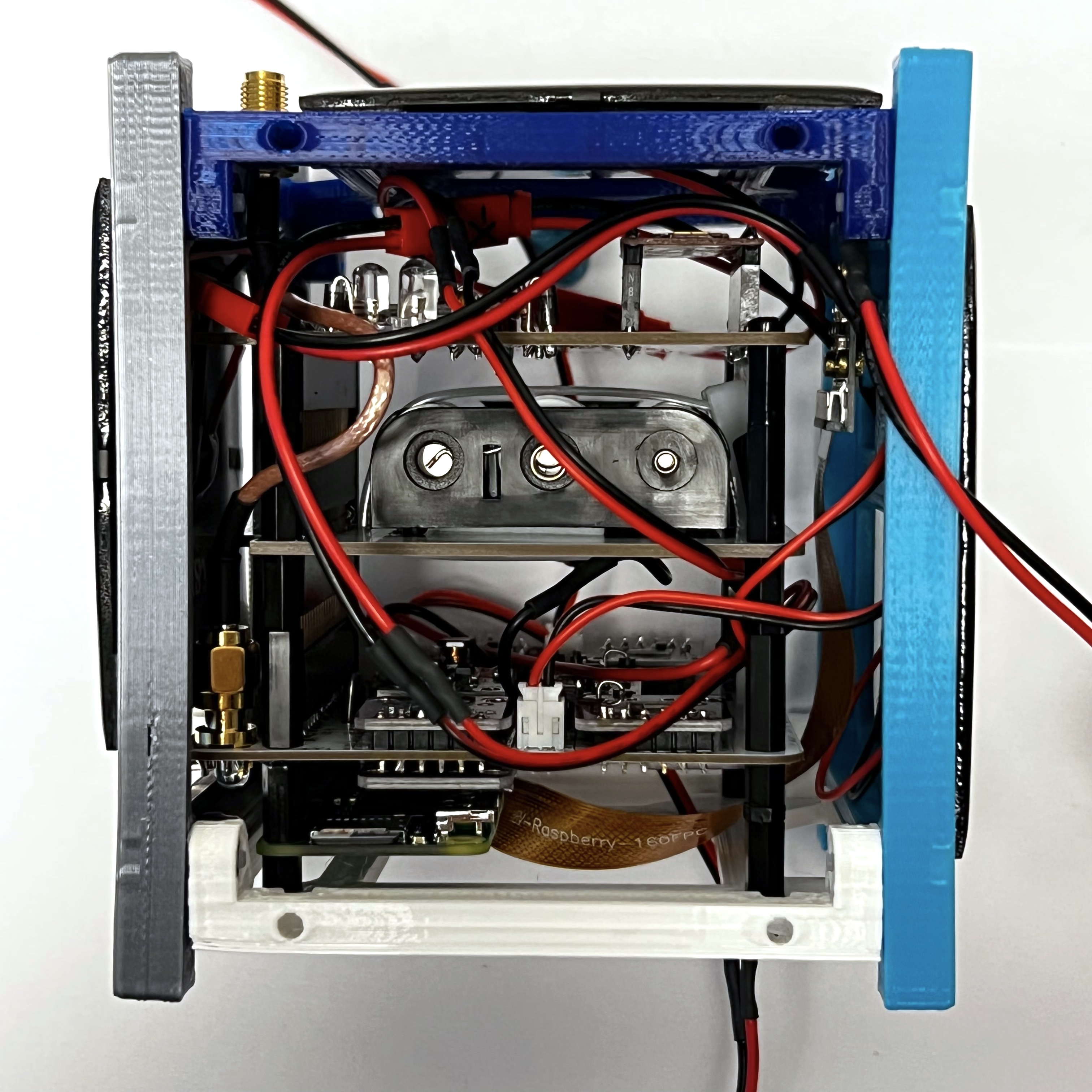
Here's how the board stack should look from the side:
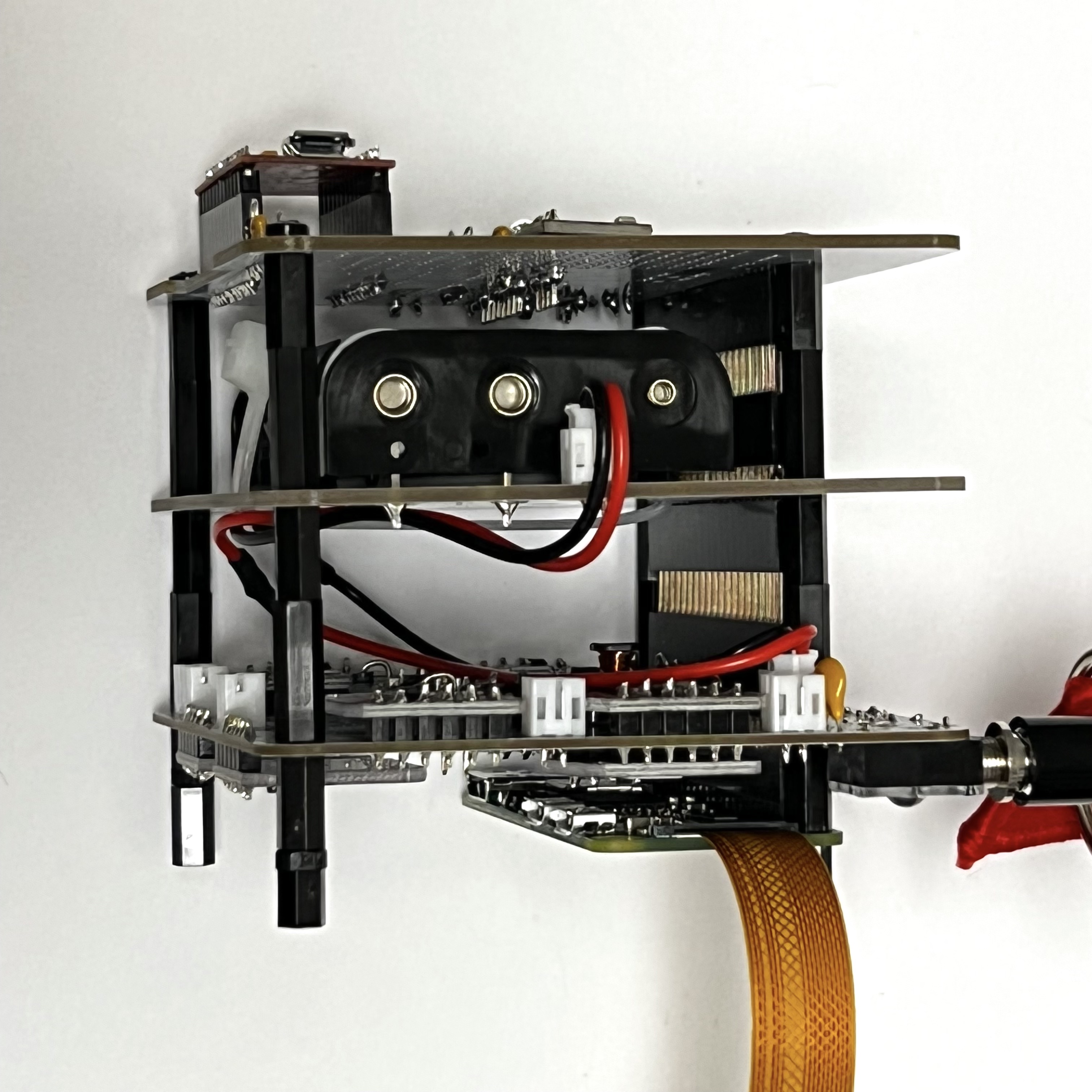
And from the other side:
You can test the CubeSatSim by removing the RBF pin. Unless the batteries are fully depleted (NiMH batteries normally come charged up), the green light on the Pi will flicker and the CubeSatSim will boot up and start running.
The green LED on the Main Board will be lit up after booting is complete and the software is running. The blue LED on the Main Board will be lit up when the CubeSatSim is transmitting. The red LED on the Main Board will be lit up when the battery is being charged by either the micro USB power supply.
The pushbutton on the Main Board can be used to reboot or shutdown the CubeSatSim. Pressing and releasing the pushbutton will cause the green LED to turn off and the Pi to reboot. Pressing and holding the pushbutton until the green LED flashes three times slowly then releasing will shutdown the Pi. Once it has shutdown, it is safe to plug the RBF pin back in. Pressing the pushbutton with the RBF pin inserted will not turn on the Pi.
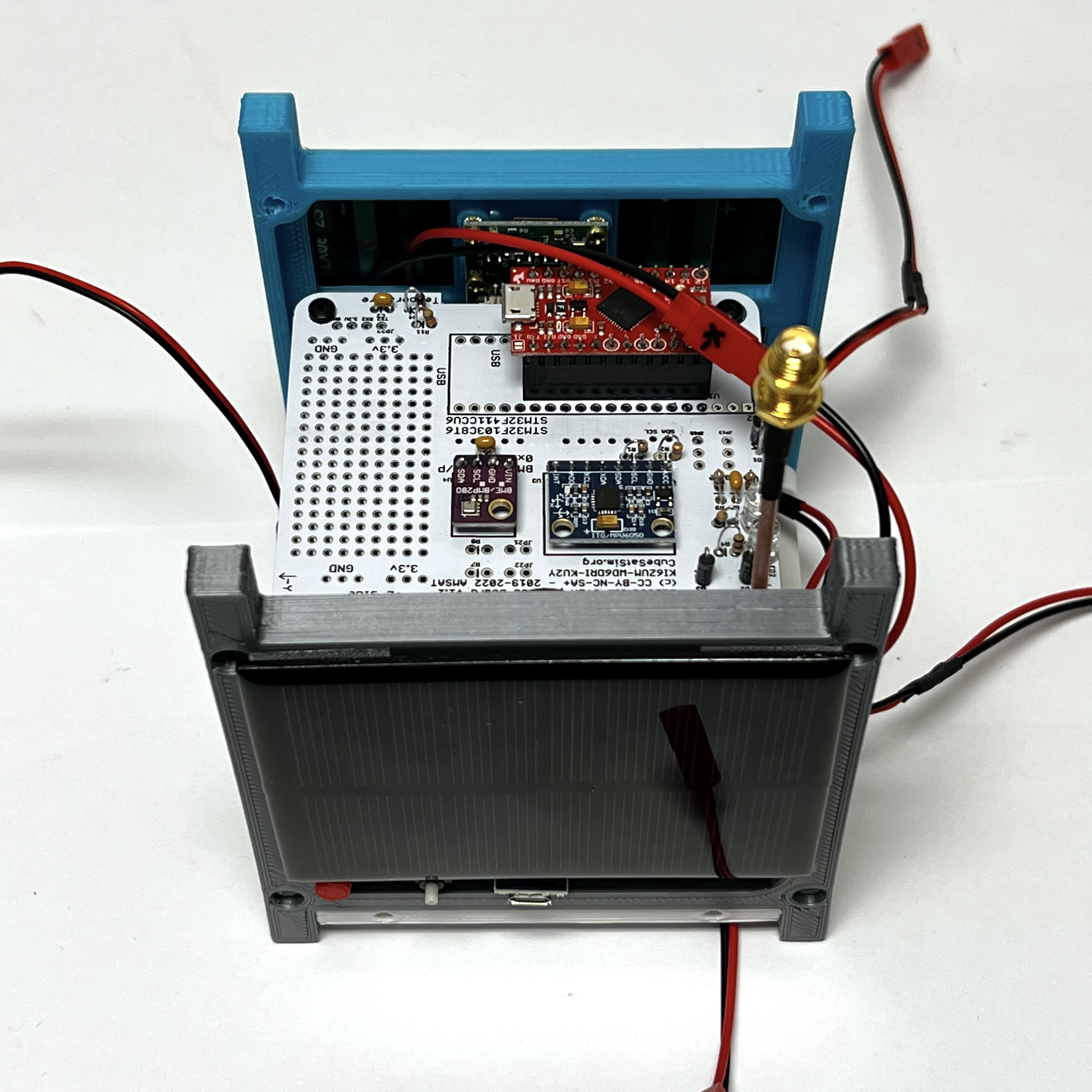
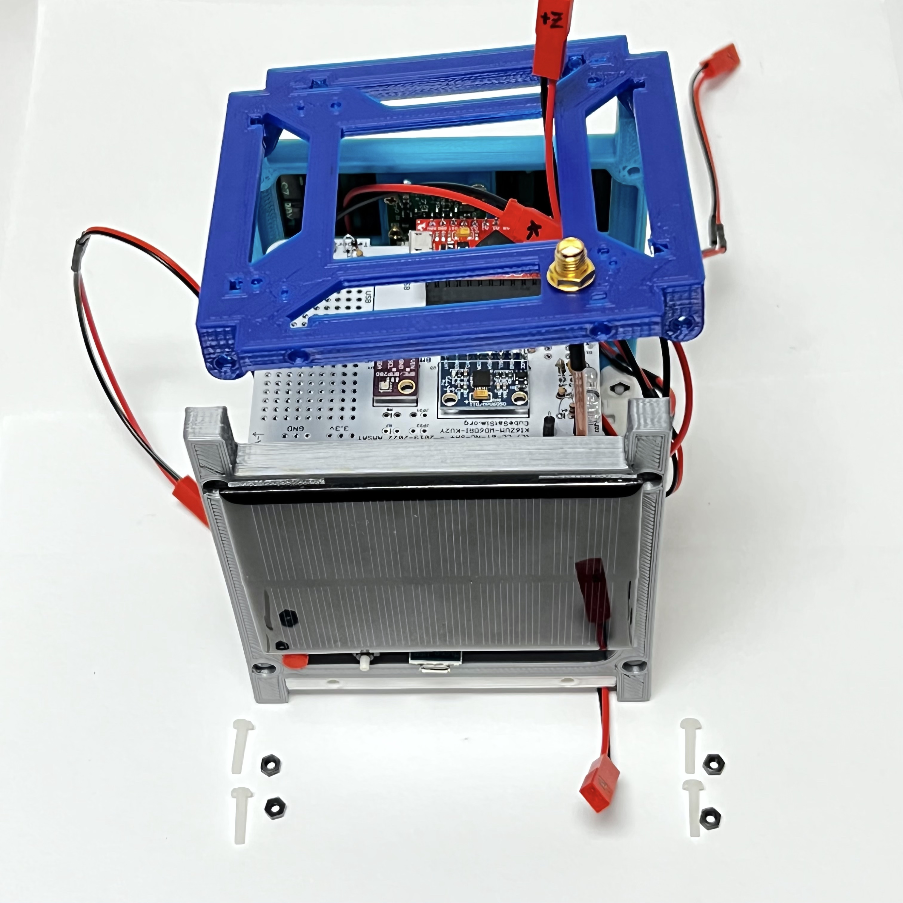
9.3 Installing the Board Stack into the Frame
The Board Stack is now ready to go into the Frame.
Video
Here is a video of the frame assembly: https://youtu.be/V1guFR5yoVY and https://youtu.be/Hg5gV504Gqw
The 1U frame of the CubeSatSim has solar panels on each face, which are labeled by the Cartesian axes X, Y, and Z. For the sides that face in the direction of the axes (see https://en.wikipedia.org/wiki/Cartesian_coordinate_system#/media/File:Coord_system_CA_0.svg), they are labeled +X, +Y, and +Z. For the sides that face in the opposite direction, they are labeled -X, -Y, and -Z. The CubeSat Design Specification (CDS) standard also has drawings showing the X, Y, and Z sides of a 1U CubeSat https://www.cubesat.org/cds-announcement. Here is a figure from that document:
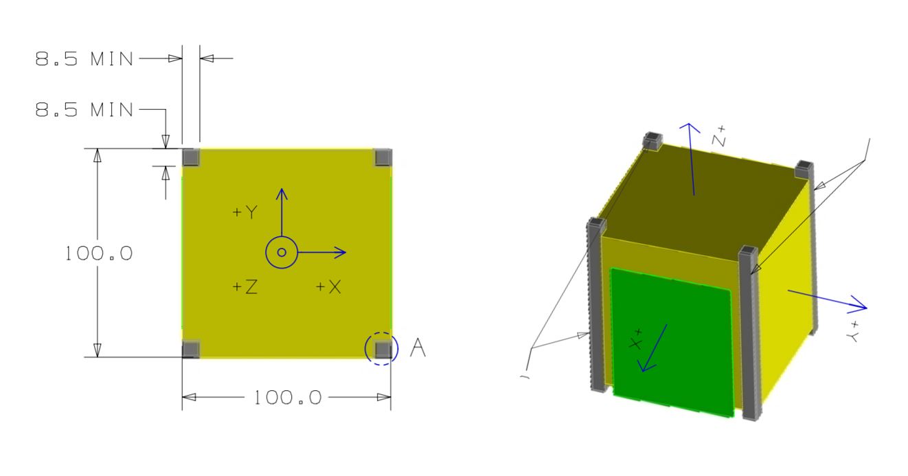
On the CubeSatSim, the +Z side is the top of the CubeSatSim, the +X side has the pushbutton, micro USB connector, and the LEDs. The Main printed circuit board has the axes labeled on it as well.
There are two sizes of solar panels used in the CubeSatSim if you aren't using a Pi Camera:
-
Four 90mm x 80mm Solar Panels for the +Y, -X, -Y, and -Z sides
-
Two 90mm x 70mm Solar Panels for the +X and +Z sides
If you are using the Pi Camera, there are three sizes:
-
Three 90mm x 80mm Solar Panels for the +Y, -Y, and -Z sides
-
Two 90mm x 70mm Solar Panels for the +X and +Z sides
-
Two 80mm x 35mm Solar Panels for the -X side
To build the frame, we will attach the board stack to the bottom frame, then attach the two sides, then the top. Note that the frame top and bottom are identical.
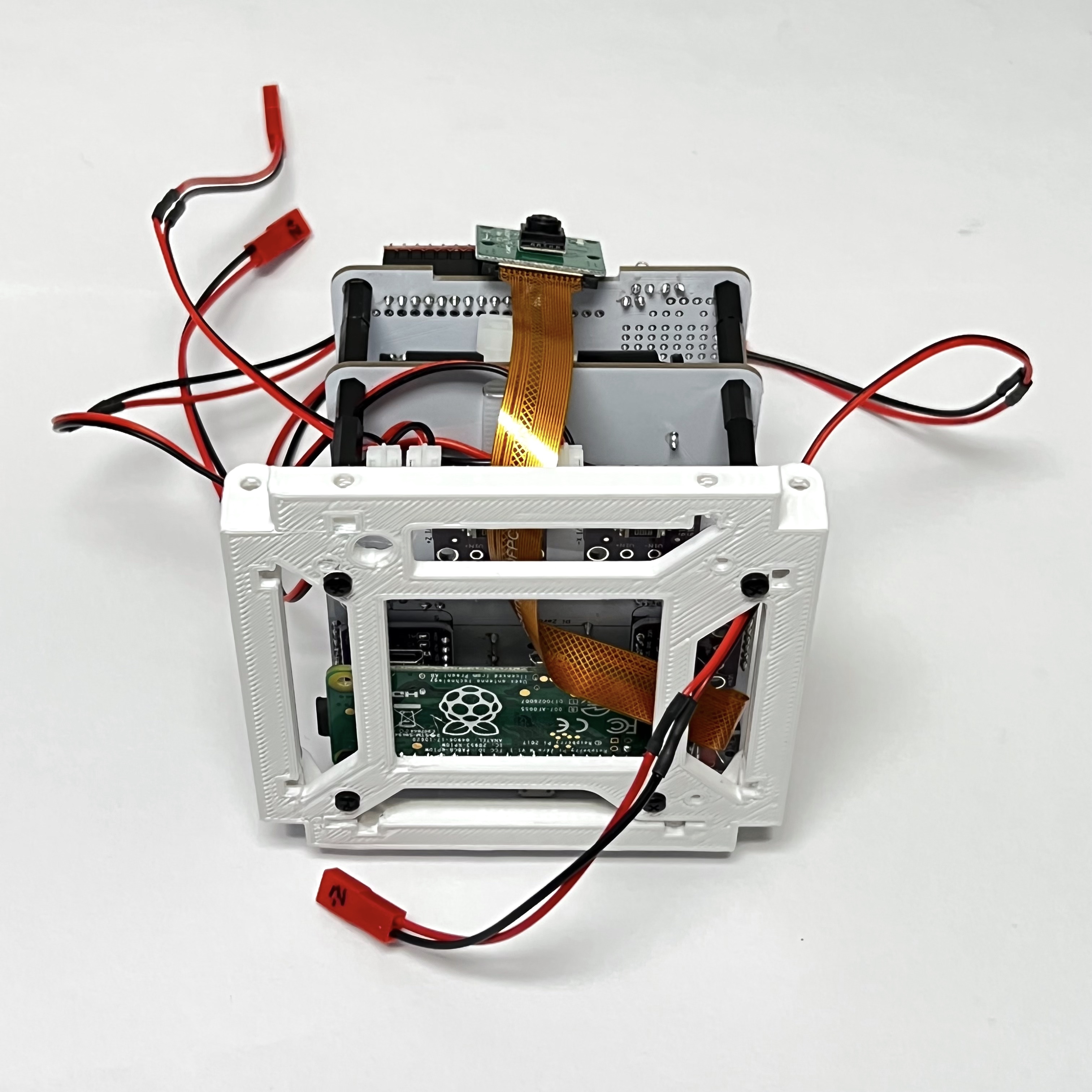
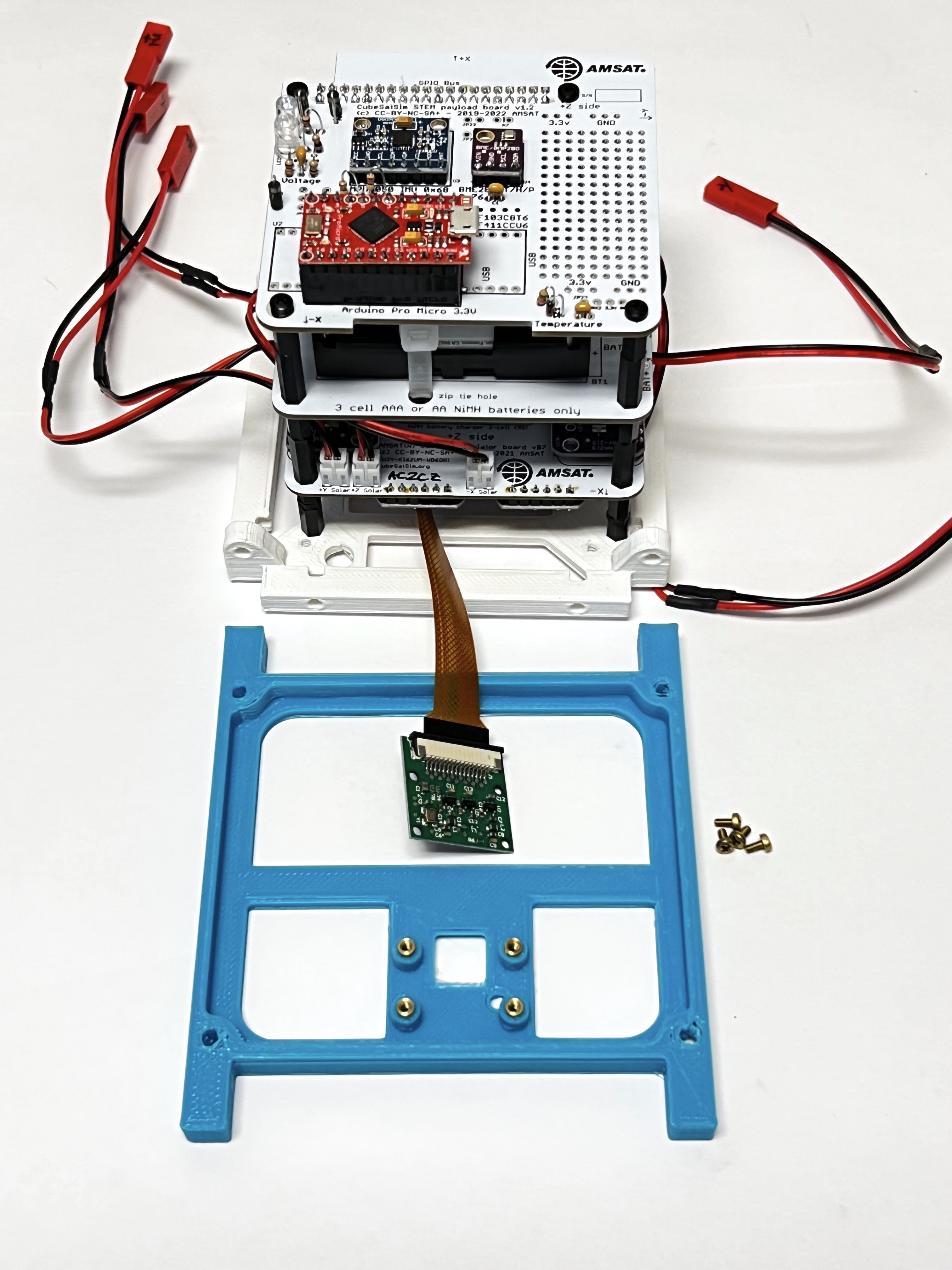
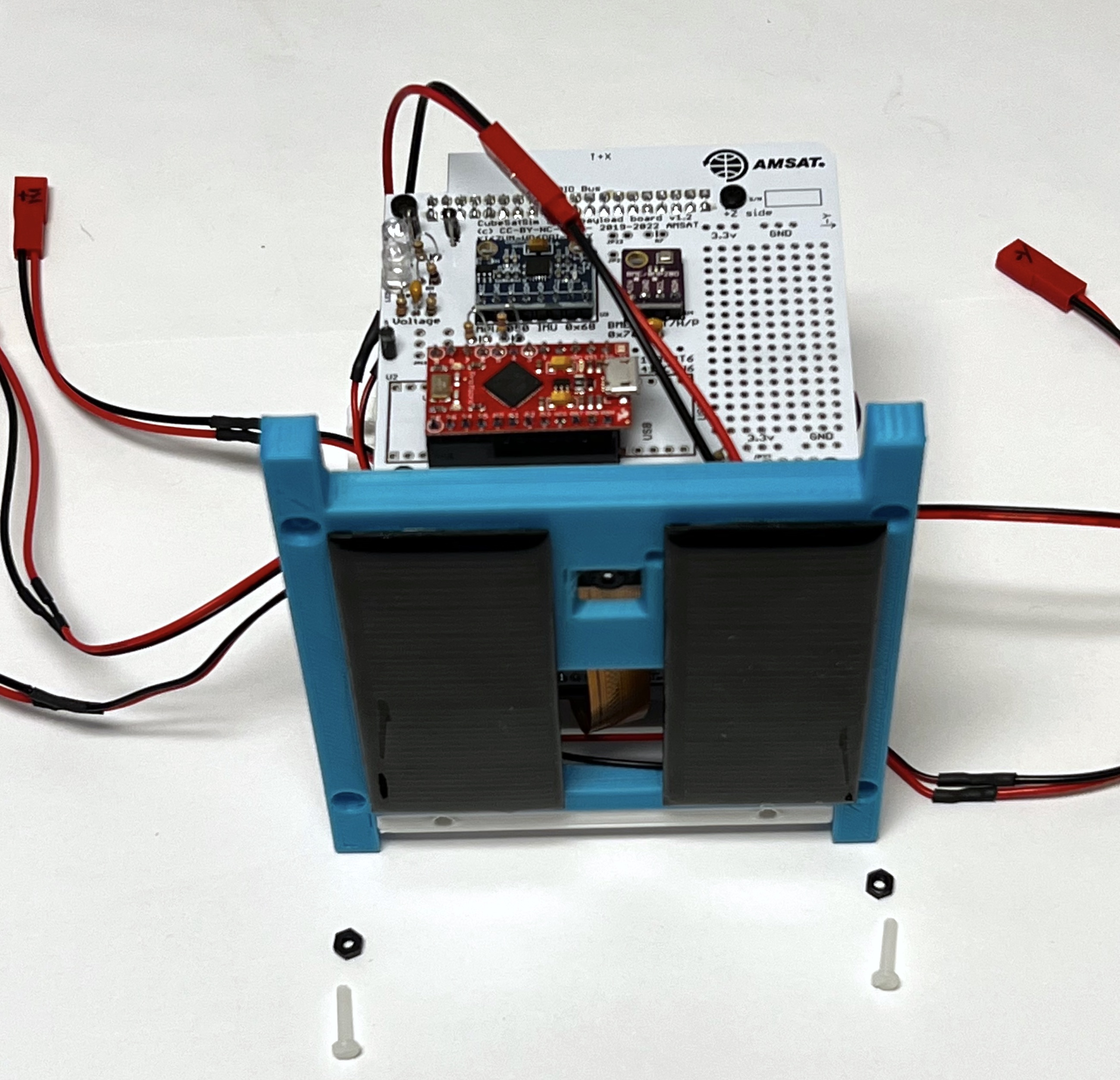
Four screws mount the bottom of the board stack to the frame bottom. In this photo, the LEDs and other connectors are facing up. The Pi Camera ribbon cable is routed as shown here:
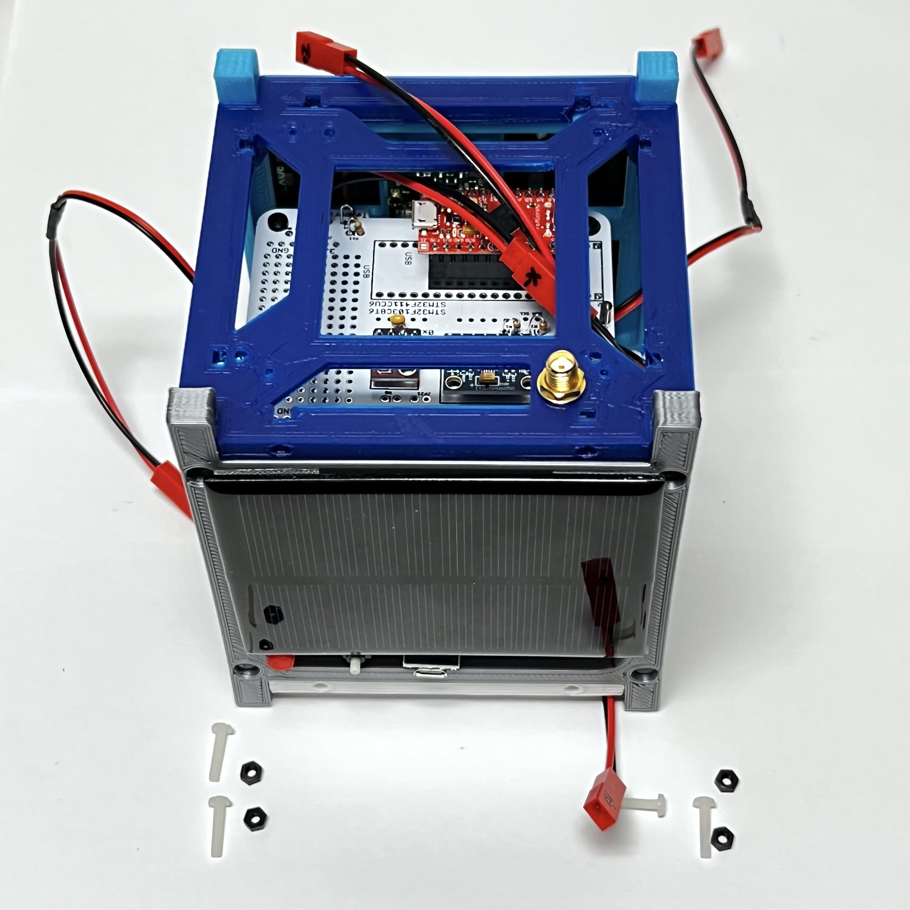
Here's how it looks from the +X side, the side with the LEDs and connectors.
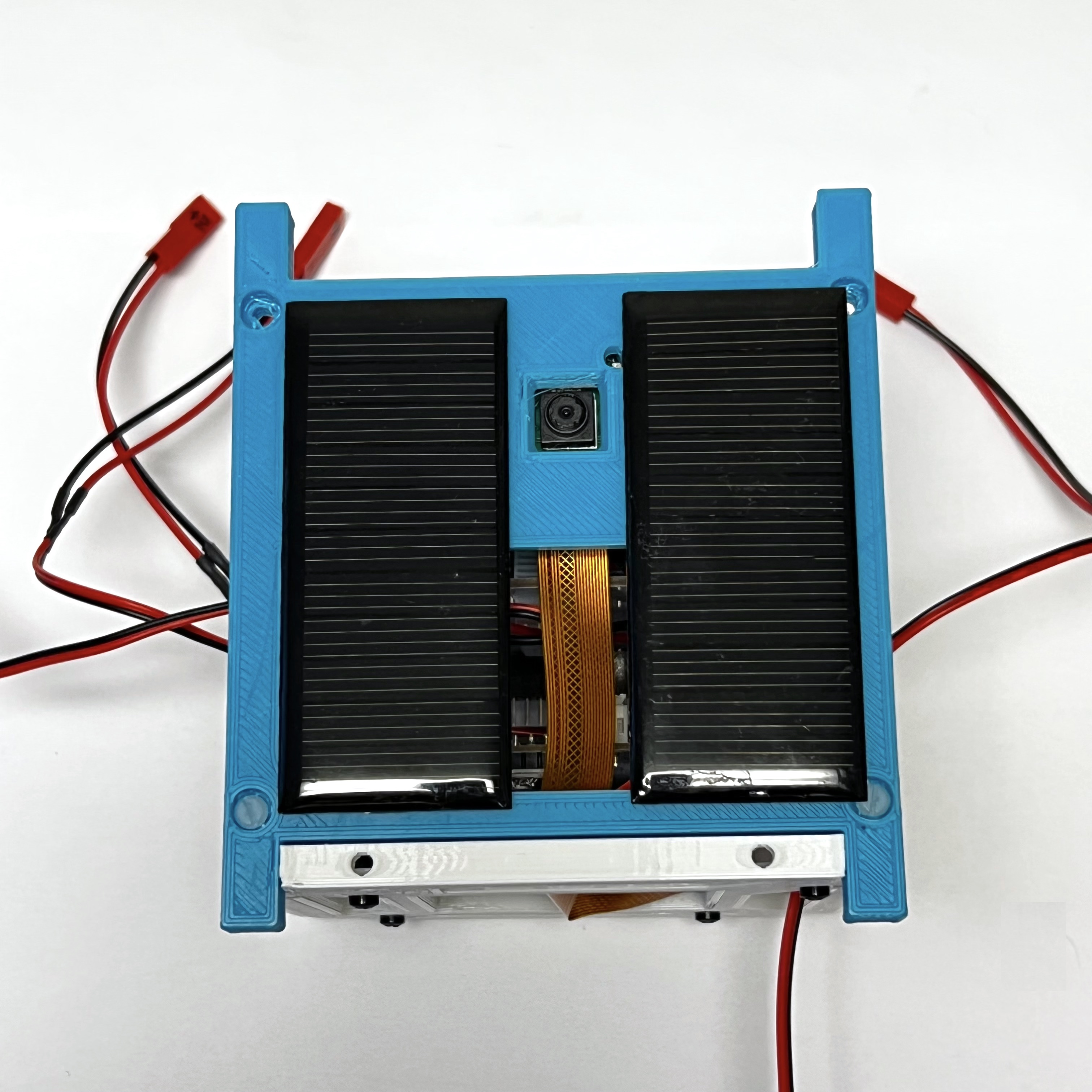
The Pi Camera should face outward on the -X side opposite the LEDs and switches as shown here:
Now, all six JST RCY wires will be mounted on the Main PCB. They should be labeled with the side: +X, -X, +Y, -Y, +Z, or -Z.
The connectors should be routed out the +Y side, except for the -Z connector which should be routed out the bottom and the -Y connector which should be routed out the -Y side.
The -Z connector should be routed out the bottom.
The first frame side to be mounted is the -X side which has the Pi Camera mount. We will mount the frame, the two small solar panels, and also the Camera using Tapered Heat-Set Inserts for Plastic, Brass, M2 x 0.40 mm, and Pan Head Phillips Screws, M2, and two nylon screws and two nylon nuts.:
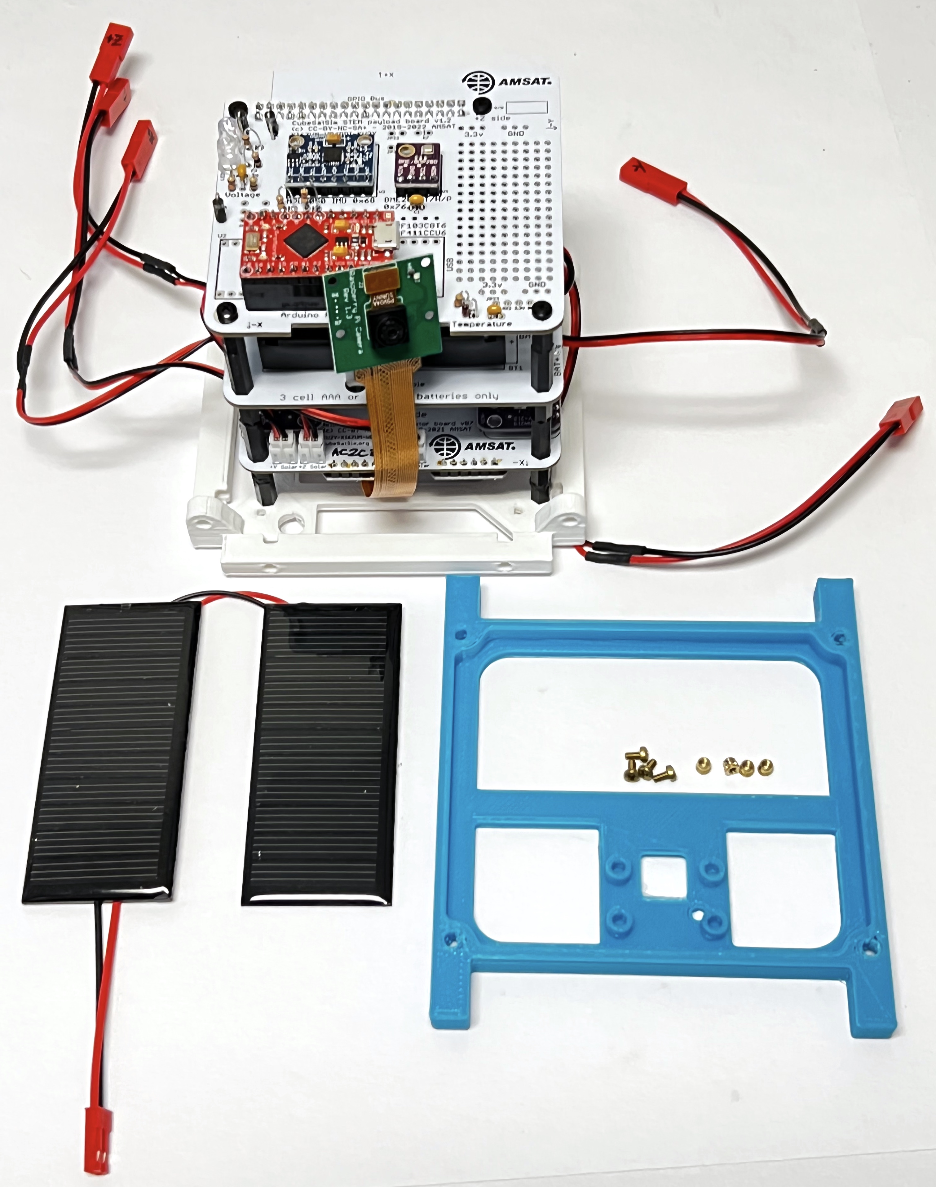
If you aren't using the Pi Camera, you will just use a normal side frame and a 90mm x 80mm solar panel. Press the inserts into the four mounting holes in the frame:
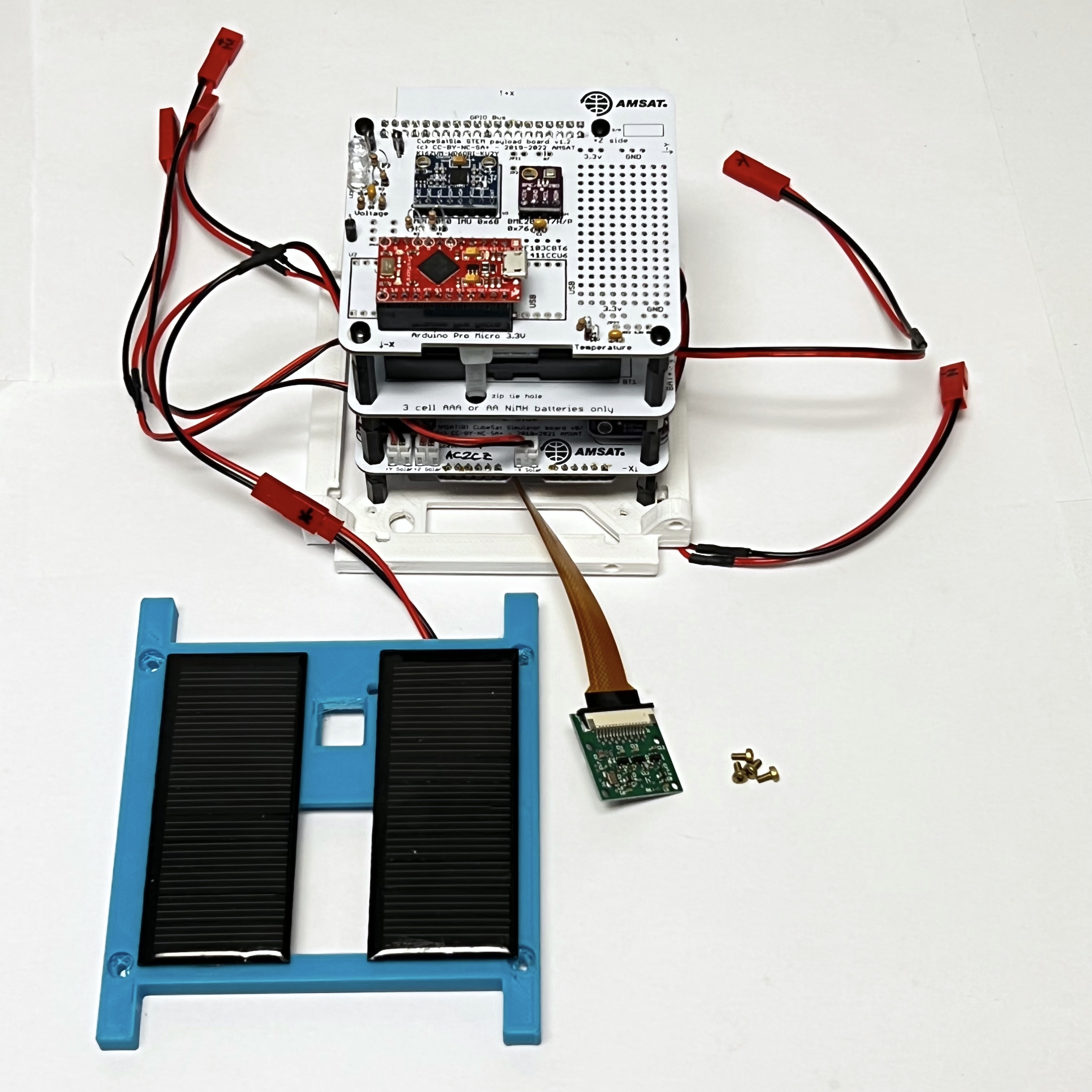
Then attach the two small 90mm x 35mm solar panels to the frame and connect the solar panels to the -X connector:
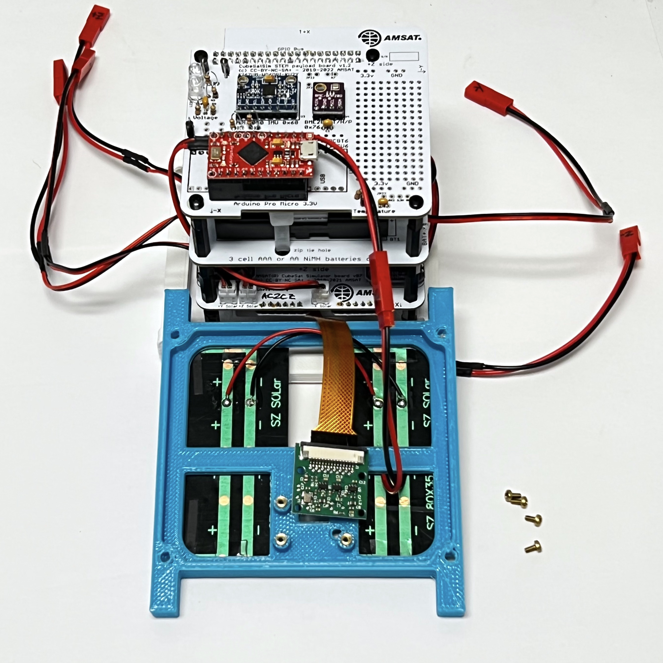
Position the frame in place and lay the Pi Camera over the mounting holes:
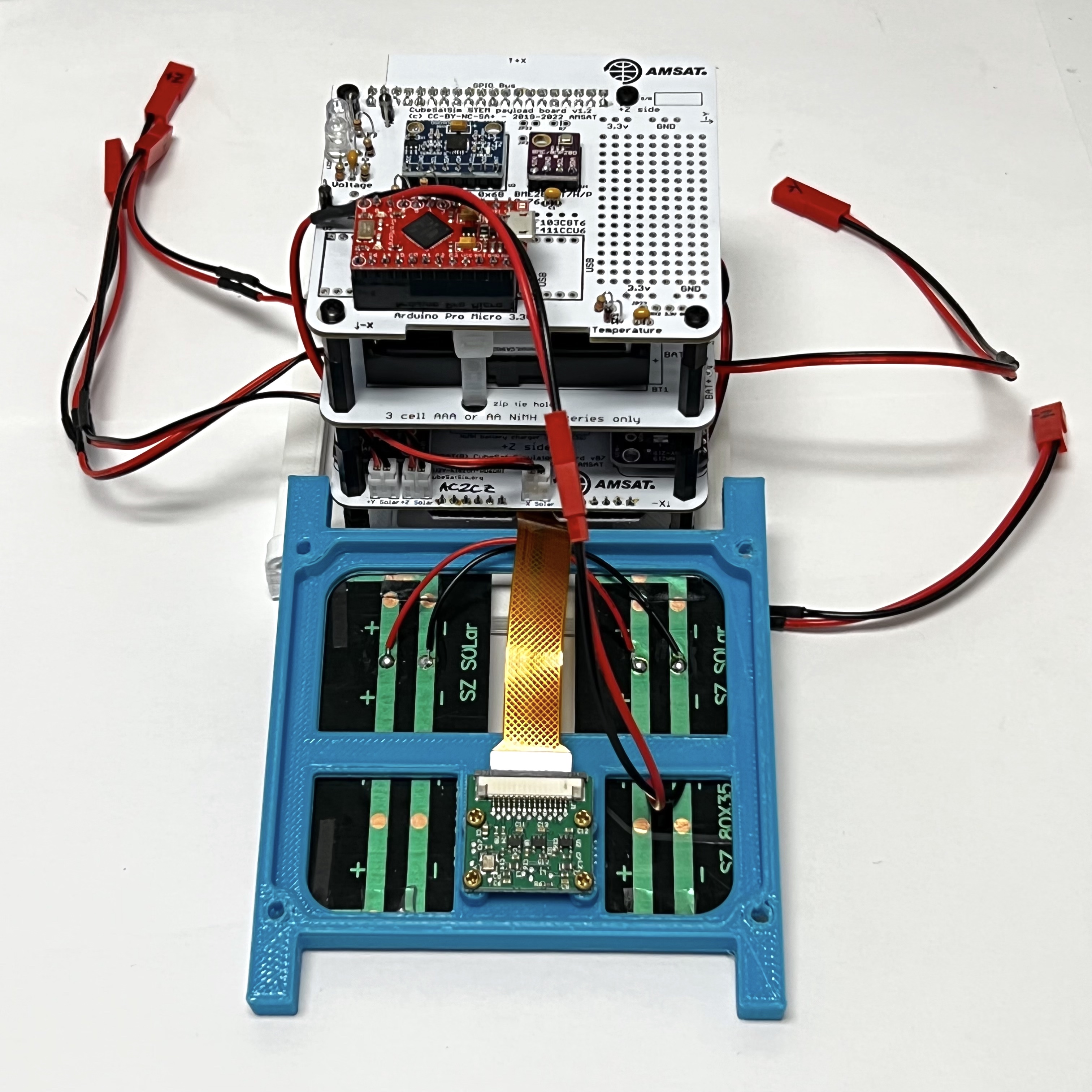
Attach the Pi Camera using the four M2 screws:
Carefully stand up the frame, being careful not to stress the Pi Camera ribbon cable and snap into position on the bottom frame:
Secure with two nylon screws and two nuts. Here is how it looks from the the -X side:
Here is how it looks from the top:
The next frame side to be mounted is the +X side. We will use the frame without the camera mount, a 90mm x 70mm solar panel, the 4" SMA coax cable, and two nylon screws and two nylon nuts.
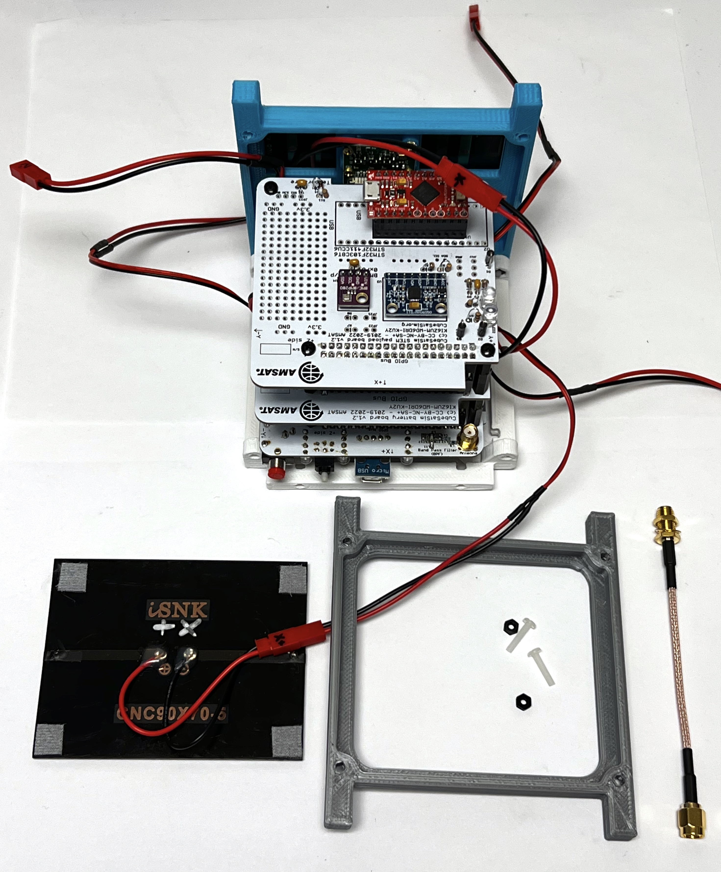
On this side with the LEDs and button, screw the SMA coax cable into the SMA connector on the Main board.
Then attach the other side frame to the base with two plastic screws and two nylon nuts, being careful of the USB and other connectors. Connect the +X connector to the 90mm x 70mm solar panel. Secure the side panel to the bottom frame using two nylon screws and two nuts.
Attach the solar panel to the side frame.
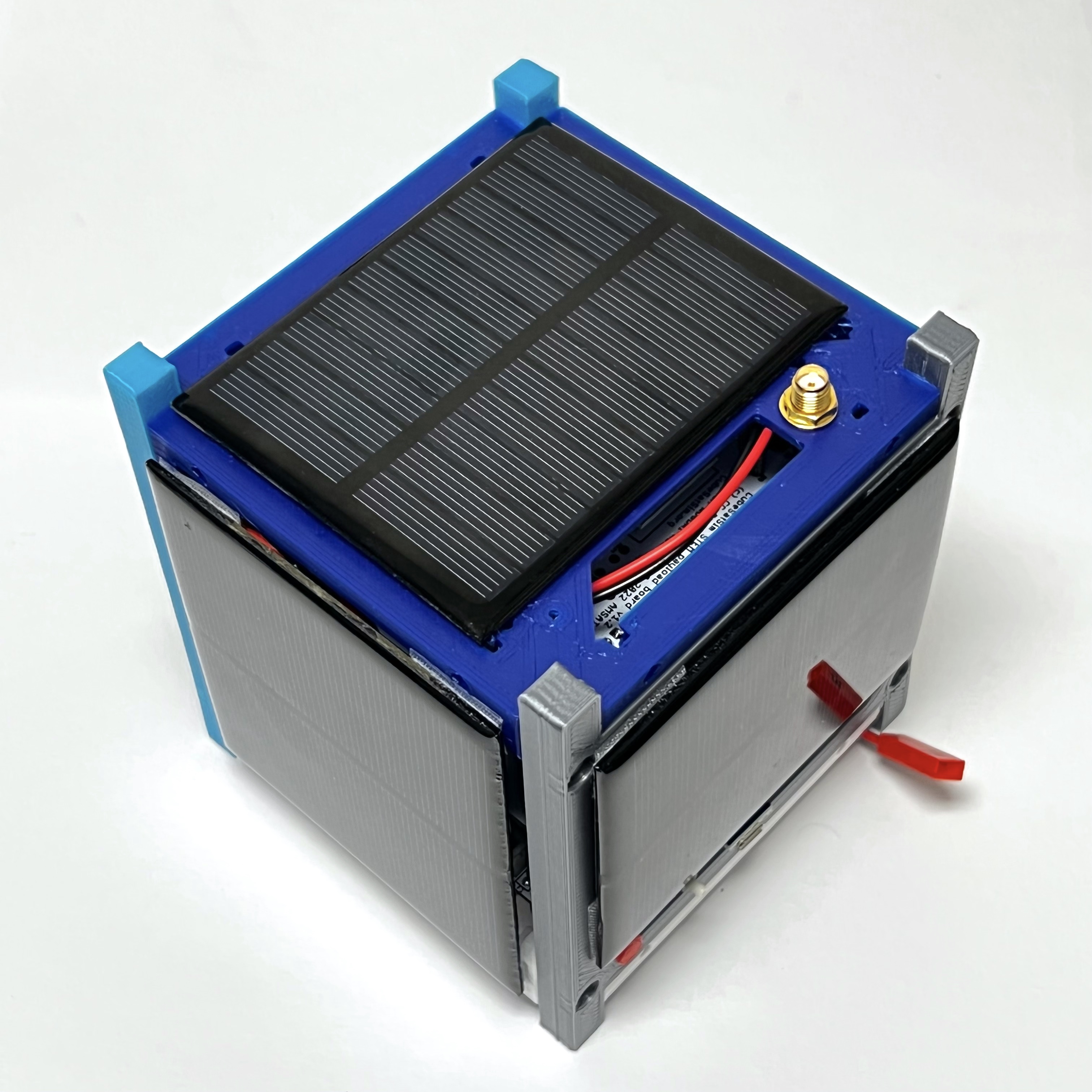
Here's how it looks from the +X side:
Put the SMA connector through the round hole in the top frame and secure with the nut.
Connect the top frame by pushing down and carefully bending the SMA cable as shown in the following photos:
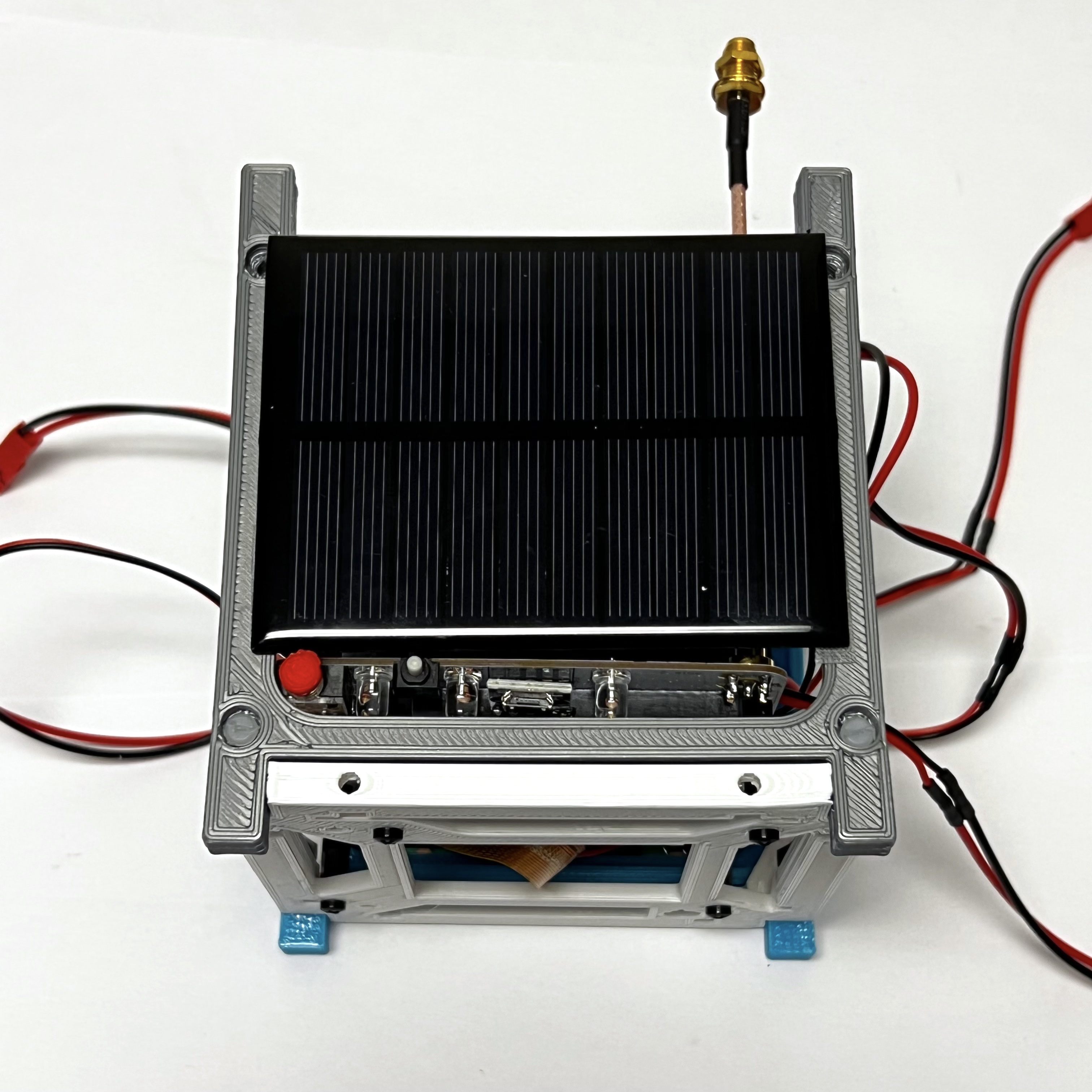
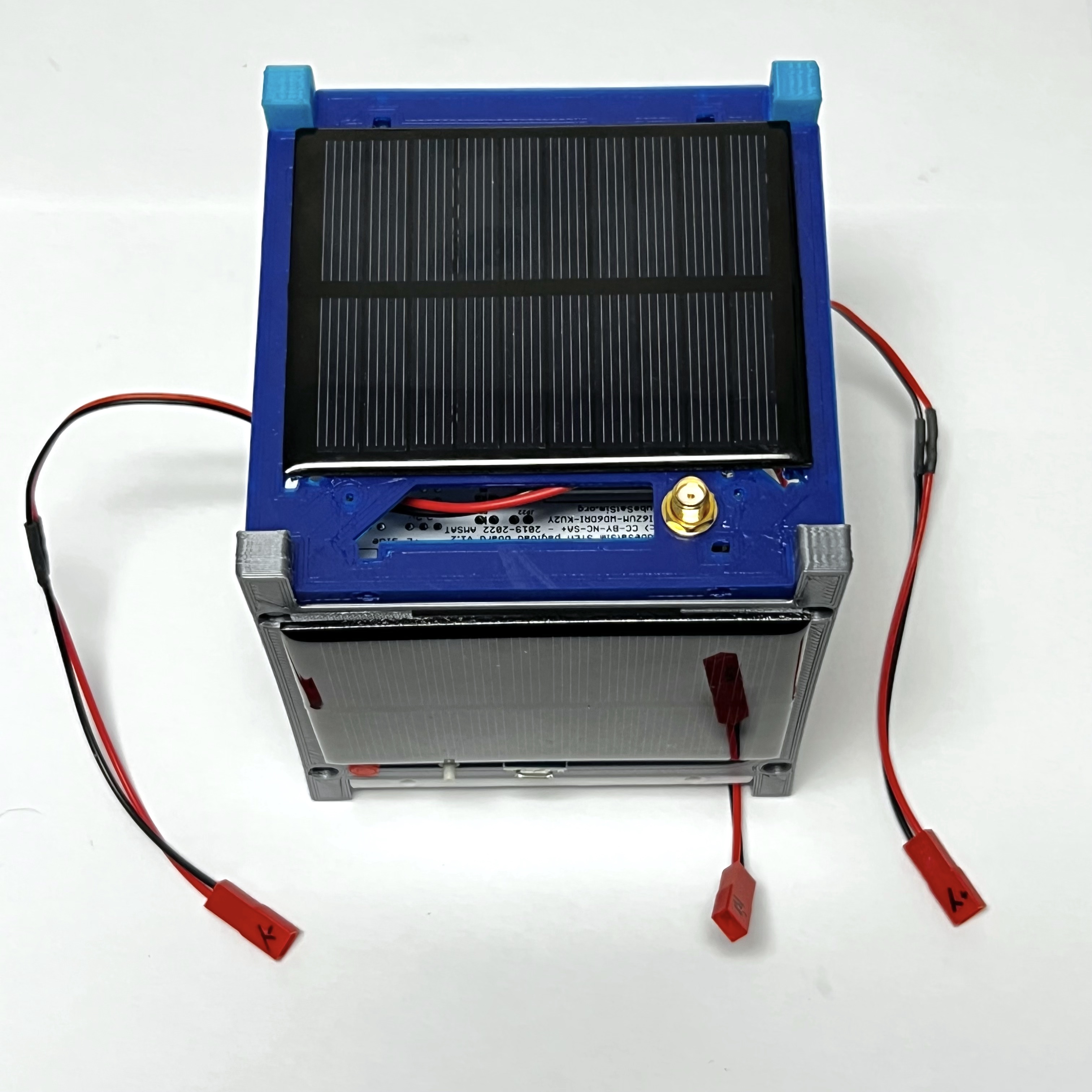
Secure the top frame with four plastic screws and four nylon nuts. Connect the 90mm x 70mm solar panel to the +Z connector.
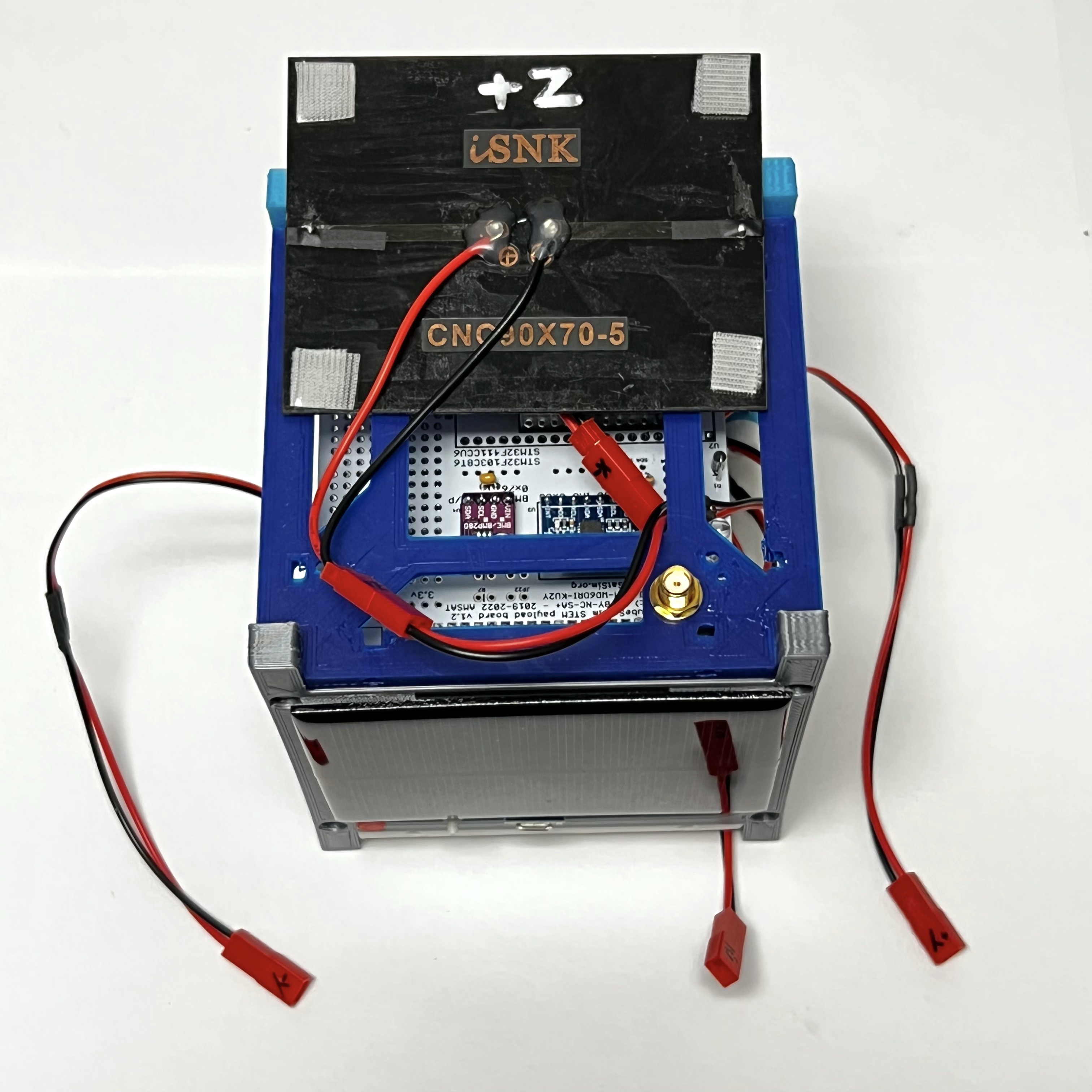
Attach the 90mm x 70mm solar panel to the top frame:
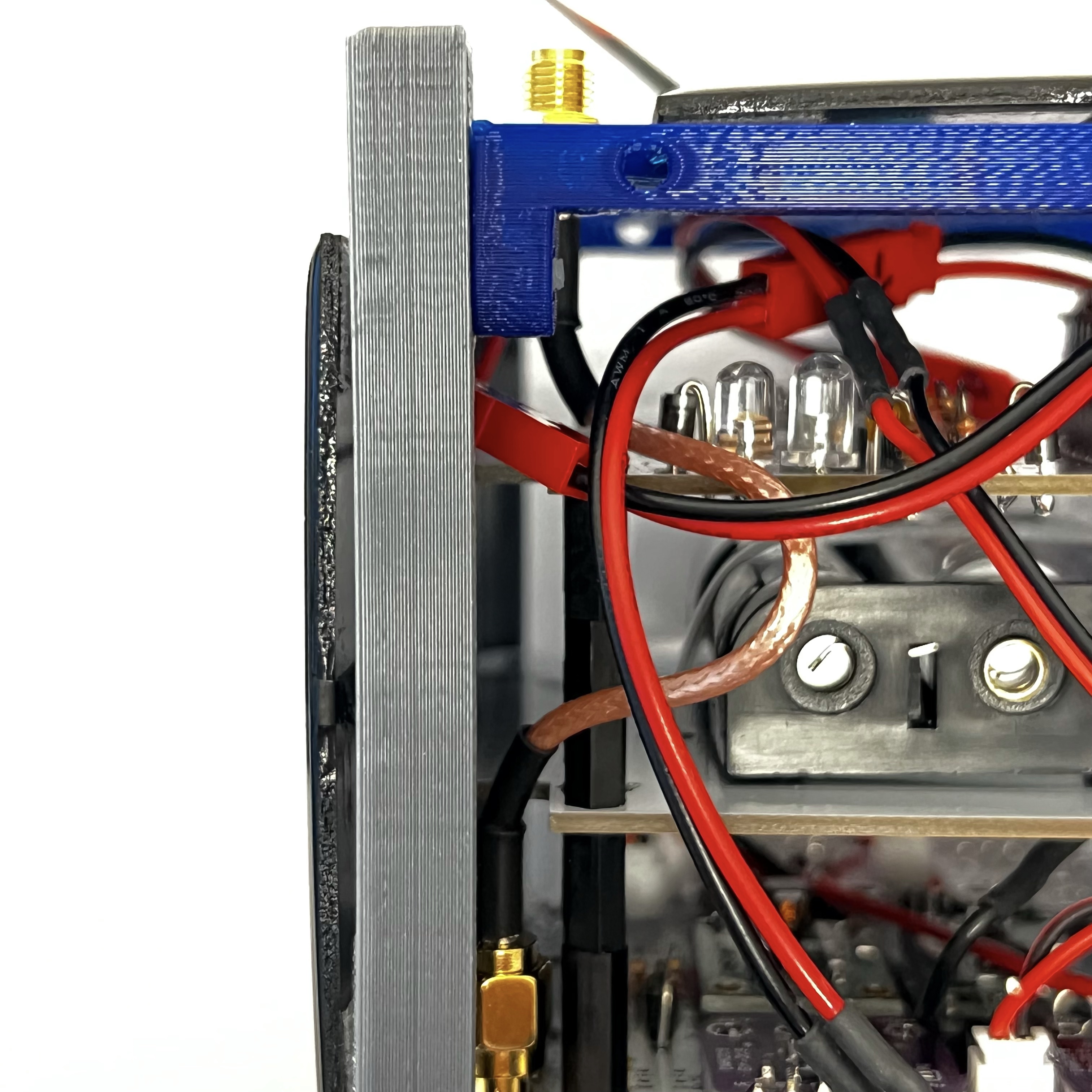
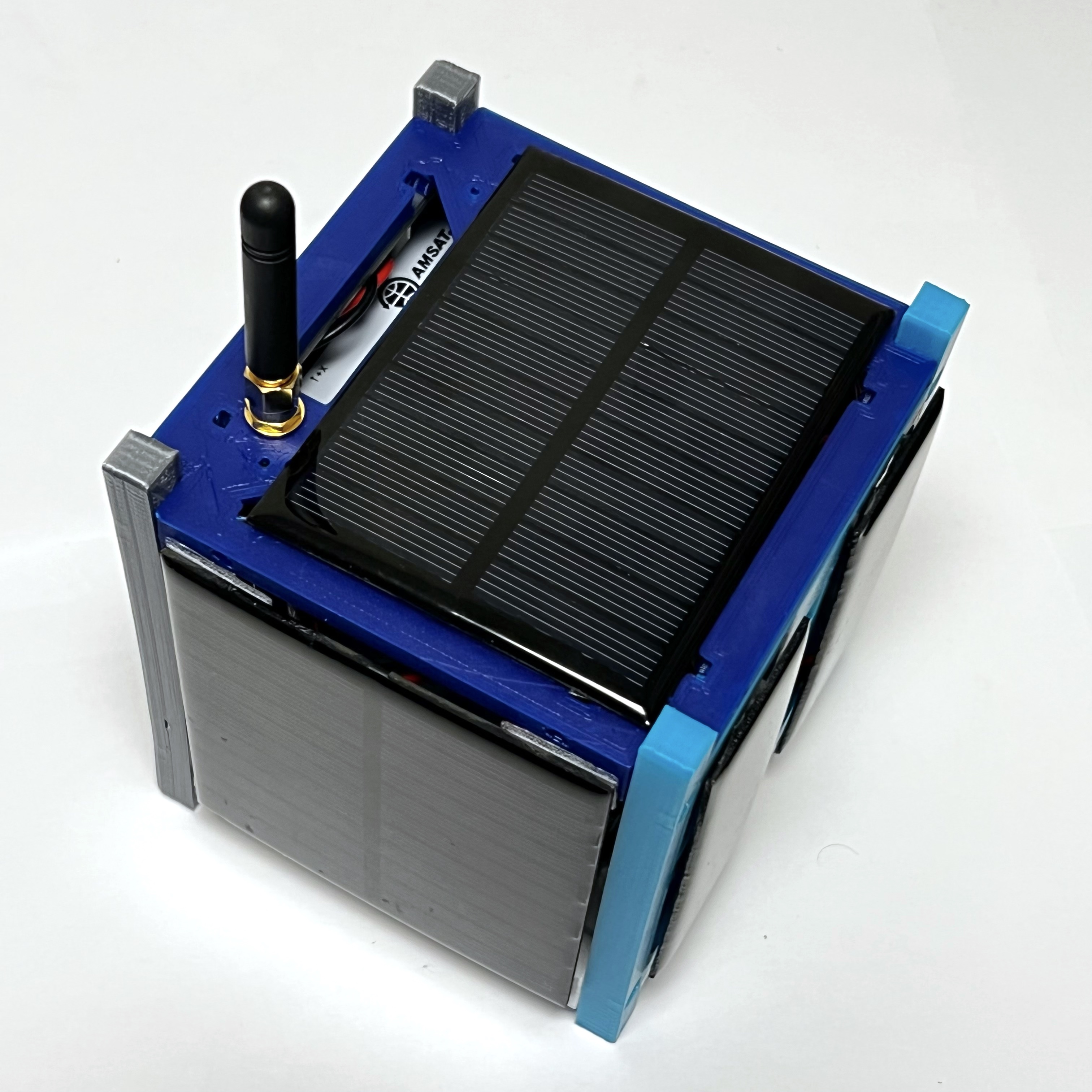
This is the view of the +Y side showing the bend in the SMA coax cable. If your coax is longer than 4", the bend will need to be bigger.
Connect a 90mm x 80mm solar panel to the +Y connector and a 90mm x 80mm solar panel to the -Y connector.
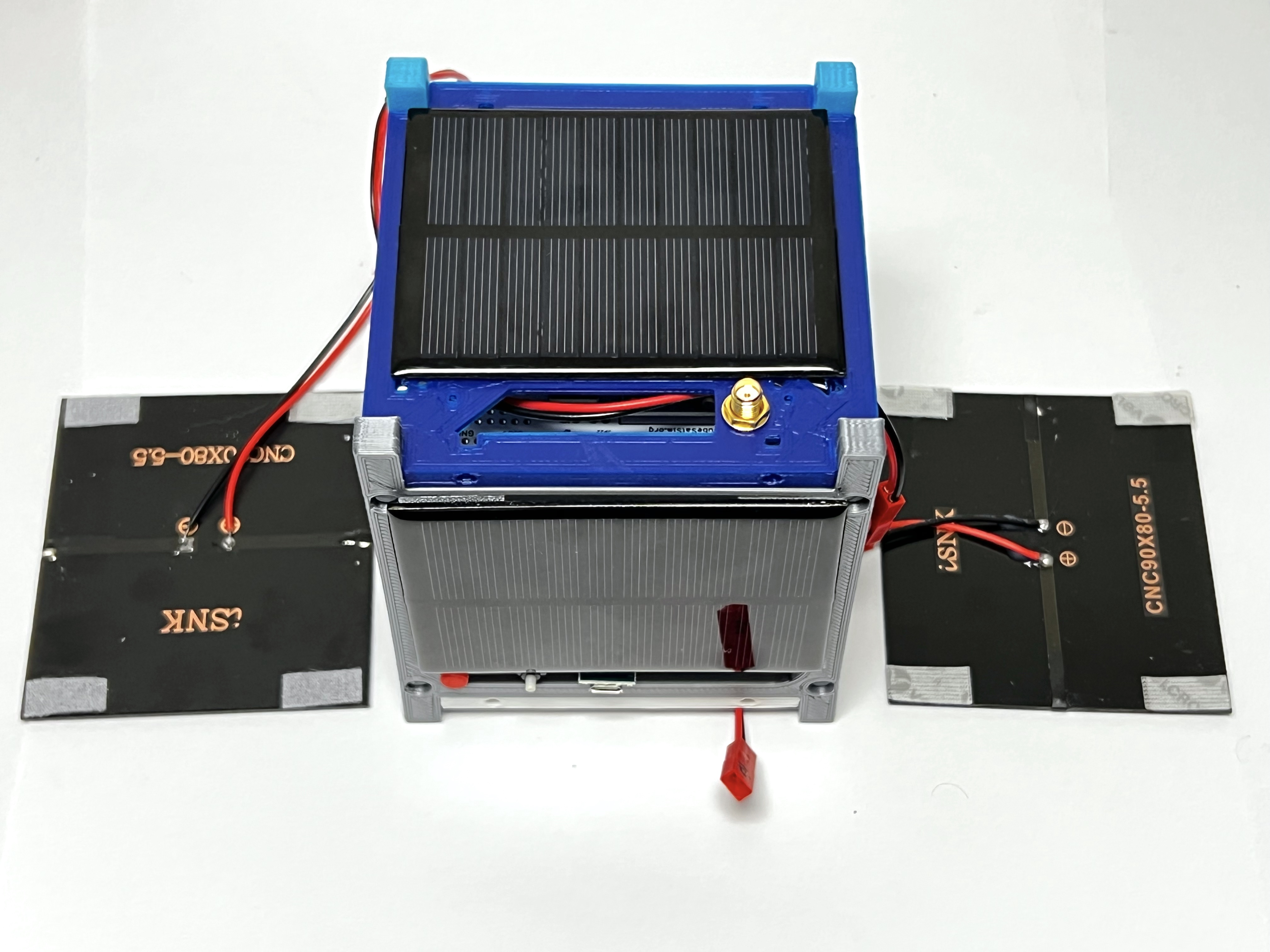
Attach the solar panels to the frame. Note that I'd recommend using velcro to attach these two solar panels and you might need to remove these panels to access connectors or change the micro SD card.
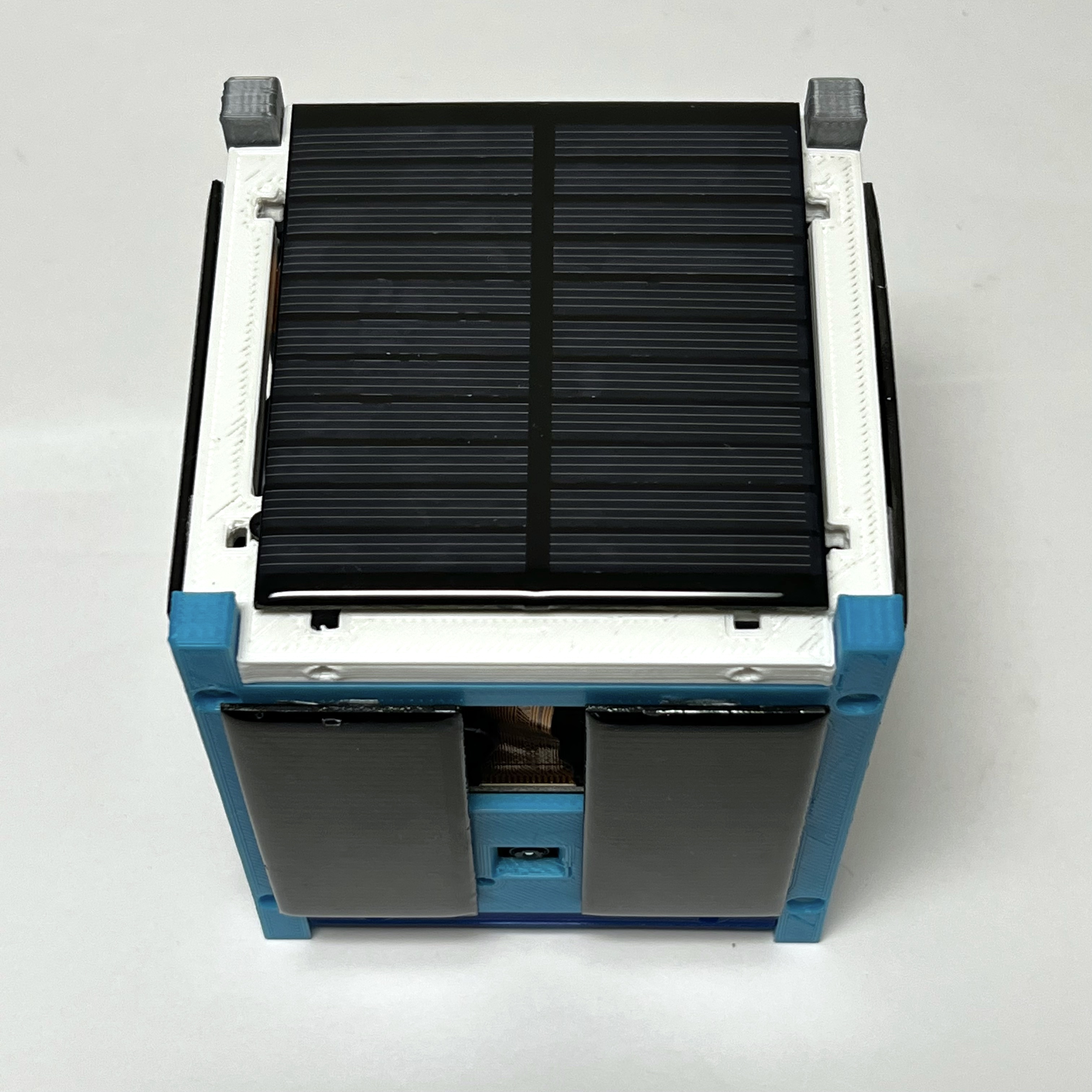
Here is the view of the +Y side and the -X side:
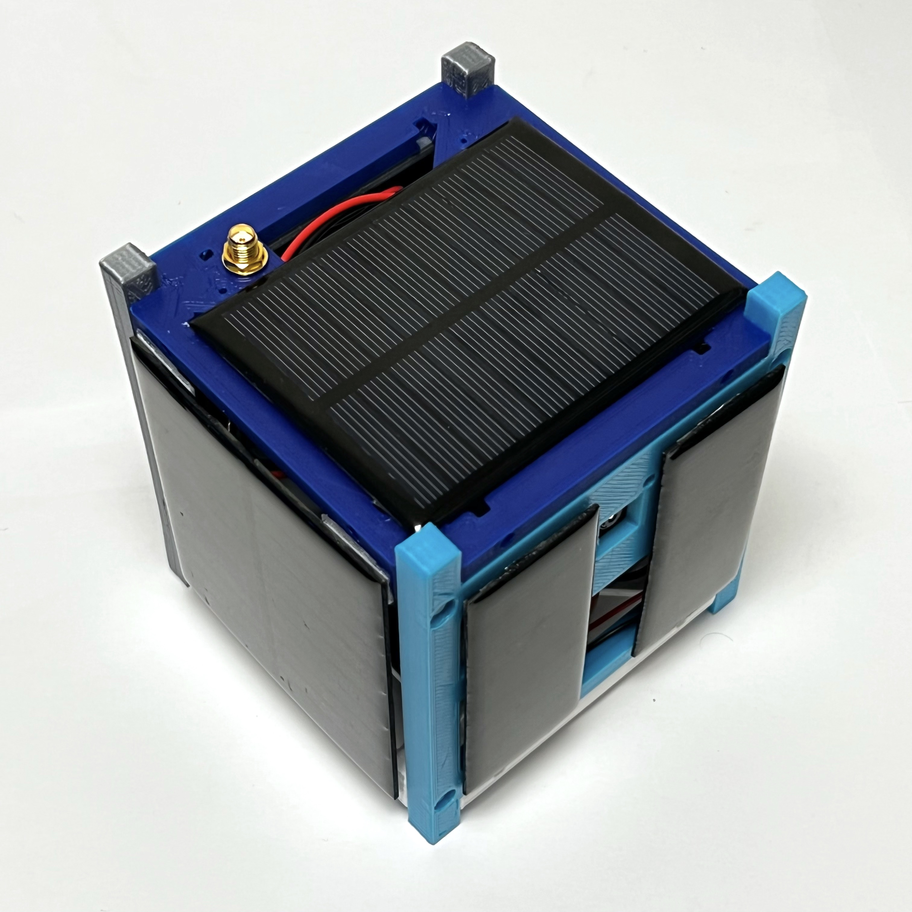
Here is the view of the -Y side and the +X side:
Flip the frame upside down, and connect a 90mm x 80mm solar panel to the -Z connector.
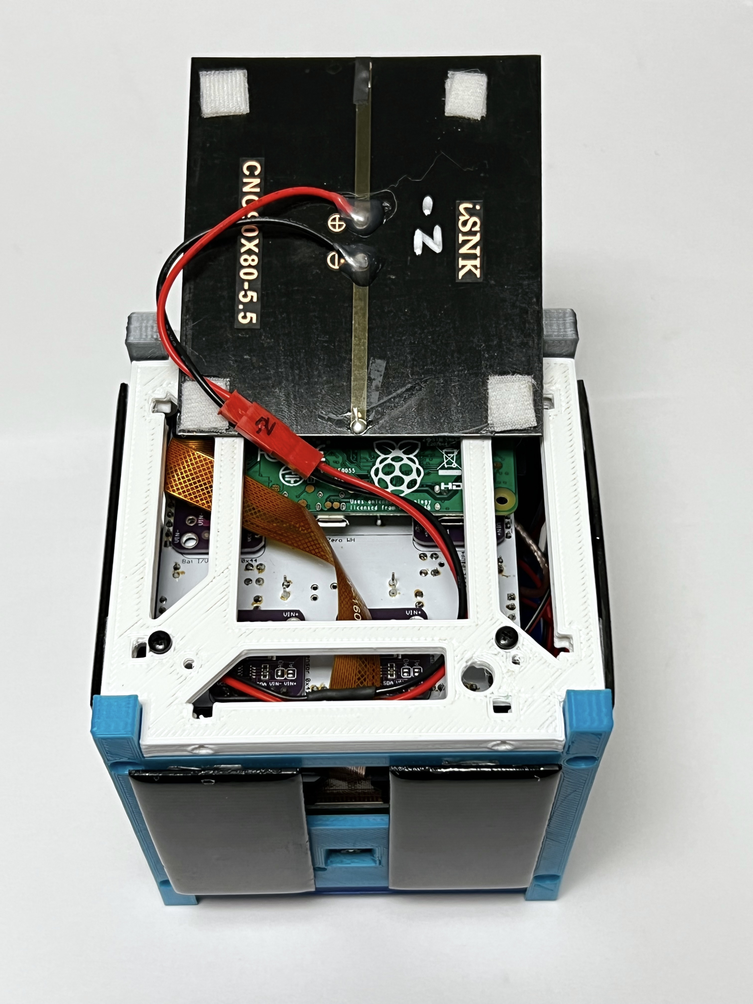
Attach the solar panel to the frame. You will likely need to double up on the double stick tape or foam to clear the screw heads.
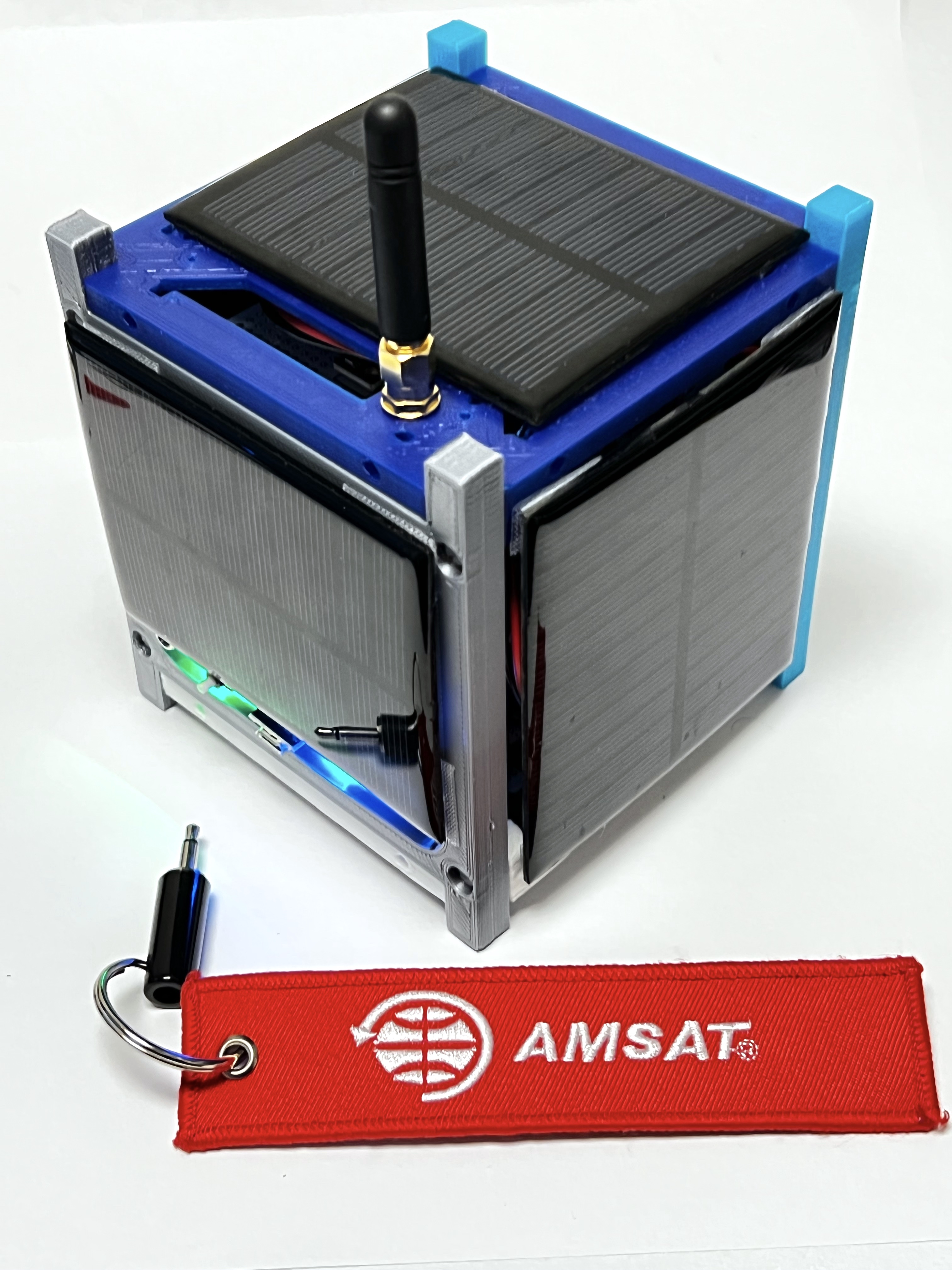
Finally, screw the SMA antenna on the top.
Your CubeSatSim is complete!