N64 Protocol - aefermiano/psxton64adapter GitHub Wiki
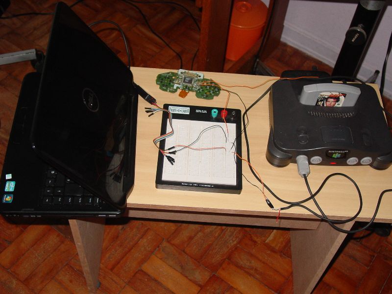
Here is a description of the Nintendo 64 controller protocol, with information I found during the adaptor development. It includes pictures that will be very useful if you want to interface with a Nintendo 64 console or controller.
I did not figure out the protocol from scratch, I used documentation from other people. Please check References Used For This Project.
The information here is enough to interface successfully with a Nintendo 64 console or controller, but not with peripherals like Rumble Pak and Memory Pak. Interfacing with peripherals is more complicated since it requires implementation of new commands and on-the-fly CRC computing. If you need this kind of information, you will be able to find it in the references I mentioned.
Electrical specifications
N64 connector pins:
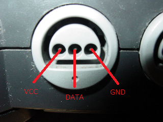
VCC is 3.3V. I don't know the max current this port can provide. Probably not too much since Rumble Pak uses external batteries.
DATA is a bidirectional line, connected using a common collector configuration. It means that instead of using 0V and 3.3V for low and high logic level, it uses a 0V and high impedance, so you will need to include a pull-up resistor to be able to read the line. If you are using a microcontroller, there is a chance you have some I/O pins with built-in pull-up already.
Protocol
- Line is kept in level high when idle.
- Each bit can be detected by a falling edge, and has exactly 4us. A zero consists in line low for 3us, and high for 1us. A one consists in line low for 1us, and high for 3us.
- Additionally to the usual bits, there are two special stop bits. "Console stop bit" is line low for 1us, and high for 2us (3us total). "Controller stop bit" is line low for 2us, and high afterwards (last bit).
- When transmitting a byte, most significant bits go first.
- A communication frame always starts with the console sending a 1 byte long command.
- The basics commands needed for interfacing with the controller or console are the commands 0x00 and 0x01. There is also commands 0x02 and 0x03, but they are related with controller paks reading (not described in this document).
- A frame for the basic commands consists of: command (console), console stop bit (console), n data bytes (controller), controller stop bit (controller).
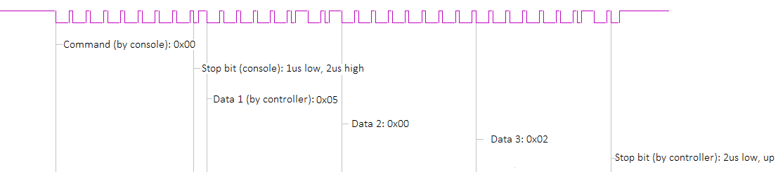
- Command 0x00 is used to identify the controller. Response is 3 bytes long, and always: 0x050002. Last byte indicates the controller pak connected, and the 0x02 means nothing is connected. Here is a trace of the communication with a genuine N64 controller:
- Command 0x01 is the polling command. N64 responds with the analog stick position and the buttons pressed. Here is the the trace, less detailed:

Note that the response contains four bytes (Data 1, then Data 2, etc). Here is the meaning of each byte (MSB first):
Data 1: A, B, Z, Start, D-Up, D-Down, D-Left, D-Right. Data 2: (not used), (not used), L, R, C-Up, C-Down, C-Left, C-Right. Data 3: Analog Stick X-Axis Data 4: Analog Stick Y-Axis
For buttons, 1 means pressed, 0 means not pressed. For analog stick, an axis position goes as two's complement, i.e. 0x00 = center, 0x01 = 1, 0xFF = -1. For X-Axis, a negative value is used for left, and a positive value for right. I don't remember which are the directions for the Y-Axis.
- Logic range for analog position is -128 to 127, however, true Nintendo 64 controller range is about 63% of it (mechanically limited), so about -81 to 81 (less for worn-out controllers). If you are interfacing with the controller, be sure to correct this range in your application. If you are interfacing with the console, be sure to not exceed these values or you will encounter glitches in some games, e.g: inability to make some combos in Super Smash Bros; some games inverting to the opposite direction once you exceed a certain value.
- Some of the references say there is a command called 0xFF that must be responded the same way as 0x00. I have never seen this command, and my adaptor works fine without being able to respond it.
Timing
Polling interval and the commands sequence depends of the game. In Star Fox 64, 0x00 and 0x01 commands are sent alternately, with intervals varying between 1ms and 20ms. For Rareware games, most commands sent are 0x01 and are about 16ms apart.
If you are interfacing with a Nintendo 64 controller, it sounds like 20ms ia a safe poll interval. One of the references say that Nintendo 64 controller responds with a significant jitter, but since I haven't seen that in my captures, a theory is that jitter may happen if polling interval is too short.
Although the waveform timing is constant in the communication involving a genuine Nintendo 64 controller, the console is very tolerant to variations. In my experiments, I tried adding ~20us before answering to a command and some pauses between response bits, and everything worked correctly. Also, if you replace the "controller stop bit" by a regular 1, everything will work correctly as well. These information may simplify your implementation.
Zelda Majora's Mask behavior
I said commands 0x02 and 0x03 responses are not needed for some games, but one of the references says the opposite. According to it, unless you respond to these commands, some games like Majora's Mask will not recognize the controller.
In my captures I confirmed that in Majora's Mask this command is indeed sent, however my adaptor does not respond to it and everything works fine. One difference from the genuine controller behavior is that my response to 0x00 command is 0x050000, and not 0x050002. It was actually a mistake, but I didn't change it since I found no problems with the games I tested on.
Techniques to read data
If you are interfacing with the N64 controller or console, you can read the data the same way console and controller do - for each bit, wait for a falling edge, and sample the data 3us after.
Although this may not be a problem for a solution involving some hardware components, it may be a problem for a software. The reason is that the protocol is too fast for some cheap microcontrollers, and you may require a high clock device to be able to detect the information this way.
You can take advantage of the well-formed waveform and use a little trick to detect the data. You can trigger the read process by the first bit falling edge, and sample the data at a fixed timing. So you can sample 3us after trigger, sleep 4us, sample again, etc. This is how my adapter works.
The problem of this solution is propagation of deltas if clocks are out of sync (as with asynchronous protocols), but I didn't have any problems regarding this.