Half Life coordinate system - advancedfx/advancedfx GitHub Wiki

The image above shows the internal left-handed Half-Life 1 coordinate system, which is equivalent to the Quake 1 coordinate system:
- Red: X-axis (forward / thumb)
- Green: Y-axis (left / second finger)
- Blue: Z-axis (up / first finger)
- Cyan: skybox planes, the text reflects the sky image orientation and order accordingly
The labels "pitch" and "yaw" reflect the engine definition and are different from definitions in aviation!
See Right-hand grip rule.
- X-axis (Roll)
- Y-axis (Pitch)
- Z-axis (Yaw)
- Half-Life 1 SDK\multiplayer\pm_shared\pm_math.c\AngleVectors
- Quake 1 Source\QW\client\mathlib.c\AngleVectors
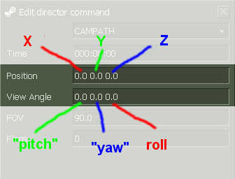
The position and angles are coded in the Half-Life order as shown in the image above (color codes and namings as in Half-Life coordinate system image in the previous section).
While you can enter negative values, and those will work correctly, the dialogue will display negative values as values greater or equal to 4096.0:
Let x be the value Valve's Campath dialog displays then:
0.0 <= x < 4096.0 --> real value = x
4096.0 <= x < 8192.0 --> real value = 8192-x
Example:
The Dialog displays a value of 8101.75.
This value is greater than 4096, so we subtract 8192: 8101.75 - 8192 = -90.25
So the real value is -90.25.
Btw Valve's DemoEdit precision of the stored values of the control points is as follows:
16 bit = 1 bit for sign + 12 bit before the point + 3 bit after the point
This means:
Greatest possible value = +4095.875
Smallest possible value = -4096.000 (?)
Smallest non zero difference between two values = +/- 0.125
Of course, the interpolation between the values / control points is much smoother.
The location / position is probably interpolated using quadratic (degree 2) polynomial splines.
The view angles are probably interpolated linearly.