Net330 Small Enterprise Packet Tracer Lab - Zacham17/my-tech-journal GitHub Wiki
Pre-Lab
- Before Starting to build the network, I made sure to save my file.
- I also set the Auto File Backup Interval to 1 minute by configuring it in Options > Preferences > Miscellaneous
Design
- The network uses the 10.x.0.0/8 network as the base network, where X is my assigned number. Therefore the network I will be using is 10.26.0.0/8.
- I will be simulating a small enterprise network for a community healthcare facility in this lab. The requirements of the network are below:
- Default Subnet (VLAN 1) used for networking services such as DHCP and DNS (150 IP's)
- "Clinic" VLAN used for Dr.'s and Nurses (300 IP's)
- "Visitor" VLAN used by patients and guests (300 IP's)
- "Office" VLAN used for administrative staff (300 IP's)
- "Counseling" VLAN used by mental health practice (150 IPs)
- I created a subnet table to outline the planning for the network, as shown below:
| VLAN ID | VLAN NAME | Hosts Needed | Network | Netmask | CIDR | Router Address | First Usable(After Router) | Last Usable | DHCP Pool Range |
|---|---|---|---|---|---|---|---|---|---|
| 100 | Clinic | 300 | 10.26.0.0 | 255.255.254.0 | /23 | 10.26.0.1 | 10.26.0.2 | 10.26.1.254 | 10.26.0.50 - 10.26.1.125 |
| 110 | Visitor | 300 | 10.26.2.0 | 255.255.254.0 | /23 | 10.26.2.1 | 10.26.2.2 | 10.26.3.254 | 10.26.2.50 - 10.26.3.125 |
| 120 | Office | 300 | 10.26.4.0 | 255.255.254.0 | /23 | 10.26.4.1 | 10.26.4.2 | 10.26.5.254 | 10.26.4.50 - 10.26.5.125 |
| 130 | Counseling | 150 | 10.26.6.0 | 255.255.255.0 | /24 | 10.26.6.1 | 10.26.6.2 | 10.26.6.254 | 10.26.6.50 - 10.26.6.225 |
| 1 | Default | 150 | 10.26.7.0 | 255.255.255.0 | /24 | 10.26.7.1 | 10.26.7.2 | 10.26.7.254 | 10.26.7.50 - 10.26.7.225 |
Network Design in Packet Tracer
- In Packet tracer I:
- Added a North Wing Edge Switch, South Wing Edge Switch, and Counseling Center Switch(South Wing), all using 2960s
- Added a North-Core Switch, South-Core Switch, and Data-Center-Core-Switch, all using 2960s
- Added 2 Servers to the Data-Center-Core-Switch, using generic servers. One for a DHCP Server and one for a DNS server.
- Added a Hospital Border/Distribution Router, using a 3560 Multilayer Switch
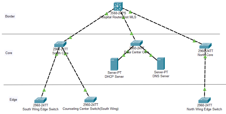
- My Packet Tracer file after doing this looked like the following:
Network Configuration in Packet Tracer
- On the switches and routers, I added the VLANs to the databases
- On the switches and router, I set trunk ports appropriately.(Connecting Switches and Routers)
Hospital Router(MLS)
- I enabled routing using the command,
ip routing - I set the FastEthernet0/1-3 ports to trunk mode using the GUI in packet tracer.
- I set the VLAN interface IP addresses using the following commands:
Switch(config)#Interface vlan 100
Switch(config-if-range)#ip address 10.26.0.1 255.255.254.0
Switch(config)#Interface vlan 110
Switch(config-if-range)#ip address 10.26.2.1 255.255.254.0
Switch(config)#Interface vlan 120
Switch(config-if-range)#ip address 10.26.4.1 255.255.254.0
Switch(config)#Interface vlan 130
Switch(config-if-range)#ip address 10.26.6.1 255.255.255.0
Switch(config)#Interface vlan 1
Switch(config-if-range)#ip address 10.26.7.1 255.255.255.0
North and South Core Switches
- I added the VLANs to the VLAN databases and configured trunk ports using the GUI on both the North and South Core switches
North and South Edge Switches
- I added the VLANs to the VLAN databases and configured trunk ports on both the North and South edge switches.
- I assigned 6 ports to the Clinic VLAN, 4 ports to the Visitor VLAN, and 6 ports to the office VLAN, using the following commands:
Switch(config)#interface range FastEthernet0/2-7
Switch(config-if-range)#switchport mode access
Switch(config-if-range)#switchport access vlan 100

Switch(config)#interface range FastEthernet0/8-11
Switch(config-if-range)#switchport mode access
Switch(config-if-range)#switchport access vlan 110

Switch(config)#interface range FastEthernet0/12-17
Switch(config-if-range)#switchport mode access
Switch(config-if-range)#switchport access vlan 120
- I then configured trunk ports on the edge switches to connect to the core switch.
Data-Center-Core Switch
- The Data-Center-Core switch only uses VLAN1, as it is intended for management use. I connected the switch to the router(no trunk ports necessary)
DHCP Configuration
- On the DHCP server, I set the IP address to 10.26.7.5, within the default networking subnet.
- I enabled DHCP in the services tab and set DHCP address pools based on the VLANs and their requirements. The settings I used for the DHCP address pools are shown below:
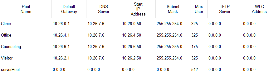
- I then connected the DHCP server directly to the Data-Center-Core switch.
Relay Agent on Data-Center-Core Switch
- I used the following commands to set the Data-Center-Core switch as a relay agent for the DHCP server:
Switch(config)#interface vlan 100
Switch(config-if)#ip helper-address 10.26.7.5
Switch(config)#interface vlan 110
Switch(config-if)#ip helper-address 10.26.7.5
Switch(config-if)#exit
Switch(config)#interface vlan 120
Switch(config-if)#ip helper-address 10.26.7.5
Switch(config-if)#exit
Switch(config)#interface vlan 130
Switch(config-if)#ip helper-address 10.26.7.5
- I tested DHCP by adding a PC with DHCP enabled. It was able to get an appropriate IP address from the address pool.
Configure Clients
- To each the North-Wing Edge Switch and the South-Wing Edge switch, I connected a Clinic PC, Visitor PC, and an Office PC. I connected each PC to their corresponding VLAN ports on the switches.
- I enabled DHCP on all of the clients
Configure DNS
- On the DNS server, I set the IP address to 10.26.7.6, within the default networking subnet.
- I enabled DNS in the services tab and created A Records for the DNS Server and the DHCP server. The A Records that I created are shown below:
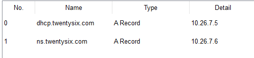
- I also updated the DHCP Server to provide the DNS server address to clients in the address pools configuration page.
Extras/Bonus
Counseling Center Edge Switch
- I set the FastEthernet0/1 port as a trunk port.
- I set 10 ports to be on the Counseling vlan (VLAN 130) using the following commands:
Switch(config)#interface range FastEthernet0/2-11
Switch(config-if-range)#switchport mode access
Switch(config-if-range)#switchport access vlan 130
- I then added two Counseling PCs to the file and connected them to the Counseling Center Edge Switch and enabled DHCP IP configuration on them.
Adding a Web Server
- I added another generic Server as a web server.
- In the services tab, I enabled HTTP and HTTPS, to configure web server capabilities.
- I was then able to browse to the Web Server in a browser from the client devices.
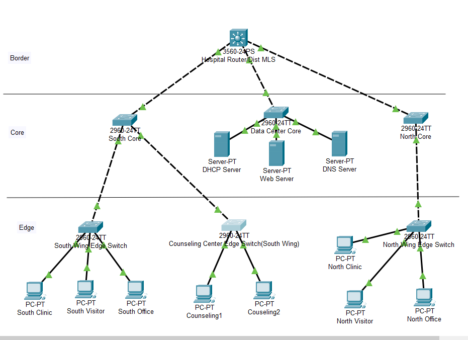
Final File Layout
Below is the final layout of my Packet Tracer File: