Net330 Lab2.1 - Zacham17/my-tech-journal GitHub Wiki
Subnet Design Lab
In this lab, I planned and designed a network simulated for a school in Packet Tracer. The network that I started with was 10.26.0.0/16, and I split that network into different subnets.
Subnet Table
The table below shows the different VLANs that I configured in this lab and information regarding each subnet.
| VLAN | VLAN_NAME | Hosts Needed | Network | Netmask | CIDR | Router Address | Last Usable |
|---|---|---|---|---|---|---|---|
| 200 | StuWireless | 900 | 10.26.0.0 | 255.255.252.0 | /22 | 10.26.0.1 | 10.26.3.254 |
| 210 | FSWireless | 650 | 10.26.4.0 | 255.255.252.0 | /22 | 10.26.4.1 | 10.26.7.254 |
| 110 | Student | 450 | 10.26.8.0 | 255.255.254.0 | /23 | 10.26.8.1 | 10.26.9.254 |
| 1 | Management | 250 | 10.26.10.0 | 255.255.255.0 | /24 | 10.26.10.1 | 10.26.10.254 |
| 100 | FacStaff | 200 | 10.26.11.0 | 255.255.255.0 | /24 | 10.26.11.1 | 10.26.11.254 |
| 130 | StuLab1 | 35 | 10.26.12.0 | 255.255.255.192 | /26 | 10.26.12.1 | 10.26.12.62 |
| 140 | StuLab2 | 35 | 10.26.12.64 | 255.255.255.192 | /26 | 10.26.12.65 | 10.0.12.126 |
Physical Setup in Packet Tracer.
- I used a preset packet tracer file with devices already placed for this lab.
- The setup represents two lab environments and two different classroom environments.
- Each room contains devices on different VLANs and has its own layer 2 switch.
- There are two layer 3 routing switches: One for the East and one for the West.
- After I finished logical configuration, I connected the devices with the appropriate cable.
- The screenshot below shows the finished setup
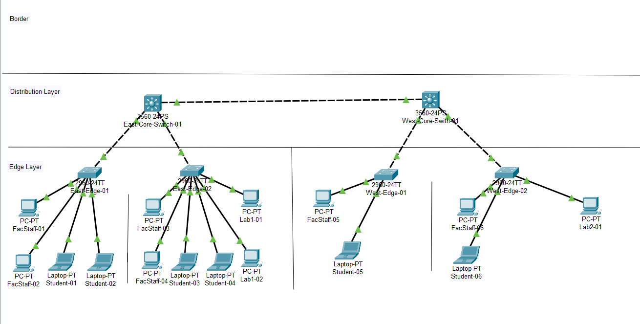 Solid Line is Straight Through and Dotted Line is Crossover
Logical Setup in Packet Tracer
- I configured the devices shown in the packet tracer screenshot above according to the the Subnet table at the top of the page.
- On each switch, I added to the VLAN database according to the following guidelines:
- 100 and 110 to all
- 130 (Lab1) in East-02 switch only
- 140 (Lab2) in West-02 switch only
- On each switch, I assigned VLANs according to the following guidelines:
- All edge switches assigned VLAN 100 (FacStaff) on ports 4-12
- All edge switches assigned VLAN 110 (Student) on ports 13-20
- East-Edge-02 assigned VLAN 130 (Lab1) on ports 21-24
- West-Edge-02 assigned VLAN 140 (Lab2) on ports 21-24
- Useful commands that I used to do this are:
interface range FastEthernet 0/x-y (where x-y is the port range)
switchport access vlan x (where x is the vlan number))
- The above commands are useful for assigning VLANs to ranges of ports.
- For host machines, such as FacStaff PCs, Student Laptops, and Lab PCs, I used the first usable host addresses in their corresponding network.
Trunk Ports
- I then configured the FastEthernet 0/1 and 0/2 ports as trunk ports on the core switches in the configuration tab for each switch. I set each trunk port for the 100, 110, 130, and 140 VLANs.
- I then configured the FastEthernet 0/1 port as a trunk port on each edge switch in the configuration tab for each switch. I set each trunk port for the 100, 110, 130, and 140 VLANs
Enabling Routing
- On the East Core Switch, I configured routing according to the table, using the following commands:
(config)ip routing
(config)interface vlan 100
(config-if)ip address 10.26.11.1 255.255.255.0
(config)interface vlan 110
(config-if)ip address 10.26.8.1 255.255.254.0
(config)interface vlan 130
(config-if)ip address 10.26.12.1 255.255.255.192
(config)interface vlan 140
(config-if)ip address 10.26.11.65 255.255.255.192
The above commands set the routing address for each vlan
Cisco Console Prefix Tips
- The prefix before typing a command specifies the mode you are in.
- Ex: (config-if) means you are editing an interface2
Trunking Between East and West
- I configured the Gigabit Ethernet 0/1 port for each core switch as a trunk port and configured them for the 100, 110, 130, and 140 VLANs and connected the core switches with a crossover cable.
- After completing all these steps, I was able to ping across all devices across all VLANs.