Q&A - WilsonGuo/FastLivo_Replication GitHub Wiki
Here's the translated version of your content:
Q&A
Factors Affecting the Quality of Color Point Cloud Imaging: Synchronization and Calibration
-
Ensuring the Accuracy of Hardware Synchronization Source Data and Interface Connections Verification Methods: A. The camera needs to verify that the image data publishing frequency is 10Hz and is published through hardware triggering at 10Hz. B. Mid360 ensures the correctness of GPRMC data and PPS trigger signal. Additional details needed for this: GPRMC data standard format is as follows:
field 0: $GPRMC, Format ID, indicating this format is the recommended minimum specific GPS/TRANSIT data (RMC) for essential location information.
field 1: UTC time, format hhmmss.ssss, representing hours, minutes, seconds, and milliseconds.
field 2: Status A: position fix achieved, V: navigation receiver warning.
field 3: Latitude ddmm.mmmmmm format (leading zeros if necessary).
field 4: Latitude N (North), S (South).
field 5: Longitude dddmm.mmmmmm format (leading zeros if necessary).
field 6: Longitude E (East), W (West).
field 7: Speed over ground (knots, 1.852 km/h).
field 8: Track angle in degrees (true, 000-359).
field 9: UTC date DDMMYY format.
field 10: Magnetic variation (000-180 degrees, leading zeros if necessary).
field 11: Magnetic variation direction, E (East), W (West).
field 12: Mode indicator, A = Autonomous mode, D = Differential mode, E = Estimated mode, N = Data not valid (3.0 protocol content).
field 13: Checksum.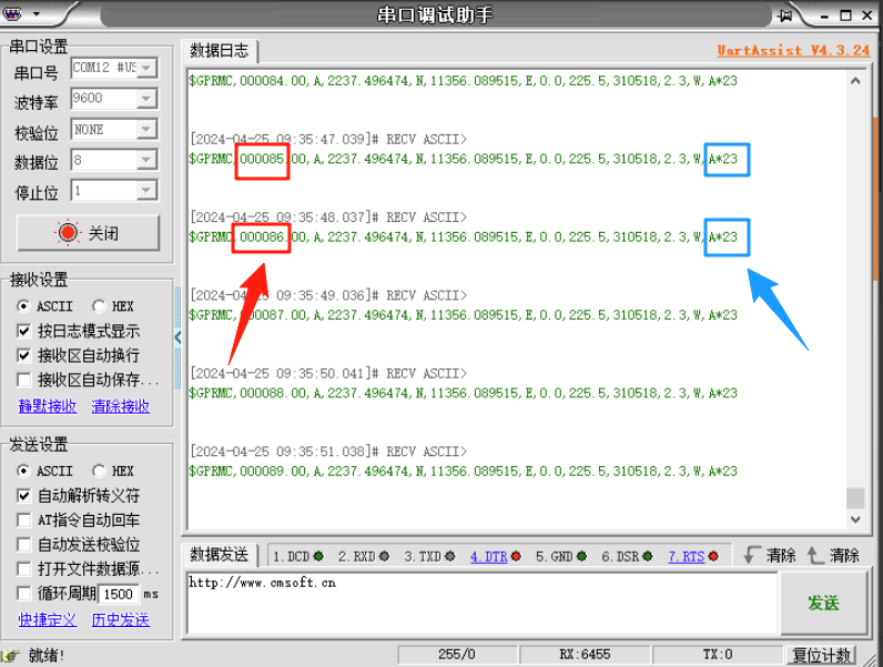
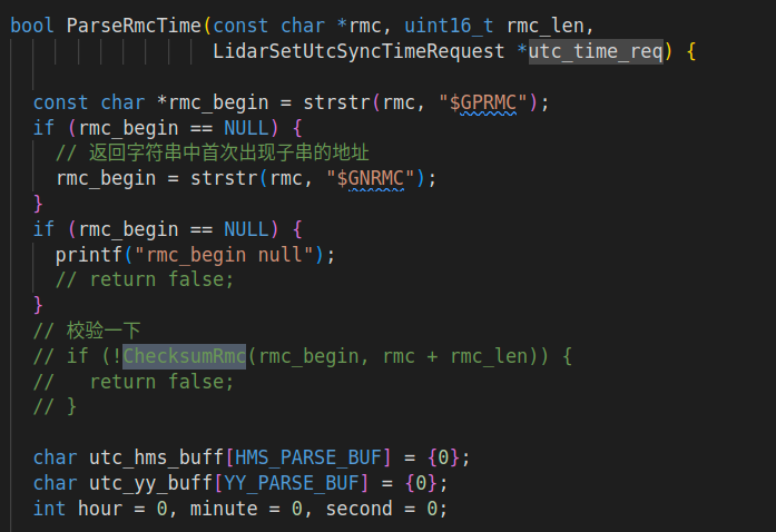
Note: The checksum in Fast Livo is fixed in STM32, and the checksum verification feature is disabled in the Aiva camera driver (which can cause data corruption or fluctuation issues). In our project, this data is directly transmitted to the Mid360 radar for processing, and we cannot modify the radar firmware, so the checksum needs to be restored as required.
Original radar SDK driver:
STM32 modification is as follows:
vu16 varl=0;
vu16 var_Exp=0;
vu16 global_time;
char snum[7];
vu16 shorttt=0;

char gprmcStr[7]="$GPRMC,";
int chckNum=0;
char chckNumChar[2];

int ss=0;
int mm=0;
int hh=0;

unsigned char result;
int i;

int checkNum(const char *gprmcContext)
{
    if (gprmcContext == NULL)
    {
        return -1;
    }

    result = gprmcContext[1];

    for (i = 2; gprmcContext[i] != '*' && gprmcContext[i] != '\0'; i++)
    {
        result ^= gprmcContext[i];
    }

    if (gprmcContext[i] != '*')
    {
        printf("No '*' found in the string.\n");
        return -1;
    }

    //printf("Final result before returning: %02X\n", result);
    return result;
}

char value_1[100]="";
char value_2[100]="";
char value_time[10]="";

char test[100]="$GPRMC,004015,A,2812.0498,N,11313.1361,E,0.0,180.0,150122,3.9,W,A*";

void TIM3_IRQHandler(void)
{
    if (TIM_GetITStatus(TIM3, TIM_IT_Update) != RESET)
    {
        TIM_ClearITPendingBit(TIM3, TIM_IT_Update);
        LED1=!LED1;
        TIM2->CNT=TIM2->ARR/2;

        PCout(13)=0;
    }

    if(ss<59){
        ss++;
    } else {
        ss=0;
        if(mm<59){
            mm++;
        } else {
            mm=0;
            if(hh<23){
                hh++;
            } else {
                hh=0;
            }
        }
    }

    sprintf(value_2, "%s%02d%02d%02d%s", gprmcStr, hh, mm, ss, ".00,A,2237.496474,N,11356.089515,E,0.0,225.5,230520,2.3,W,A*");
    strcpy(value_1,value_2);
    chckNum = checkNum(value_1);
    sprintf(chckNumChar, "%02X", chckNum);
    printf("%s", value_2);
    printf("%s\n", chckNumChar);
}
Criteria for successful synchronization are as shown in the following image:
Summary:
-
Reproducing Fast Livo is relatively complex, taking approximately 6 weeks (structure printing, hardware assembly, driver debugging, calibration, synchronization, adaptation, data collection, performance comparison, and parameter optimization), but ultimately meeting the standards.
-
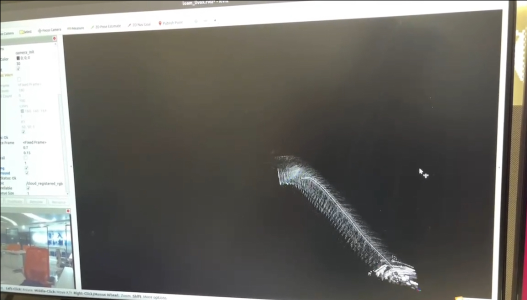
Proper calibration (intrinsic and extrinsic) is crucial for accurate coloring of point clouds.
-
In addition, multi-sensor synchronization is crucial, directly affecting whether visual odometry and radar odometry can be correctly fused rather than negatively optimized.
Poor synchronization can easily lead to odometry errors.
- Currently, Fast Livo's support for Arm onboard computers is not optimal; it is recommended to use an X86 computer (such as NUC) directly.
-