Device configuration and assembly - WilsonGuo/FastLivo_Replication GitHub Wiki
References
Official Hardware Connection Guide
Differences:
- Replace Avia with Mid360
Some software or driver modifications are required.
Hardware:
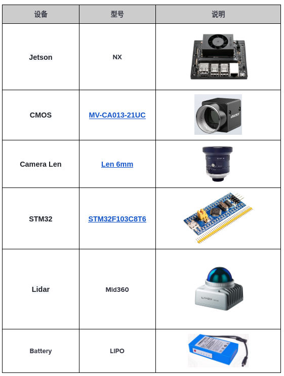
Assembly:
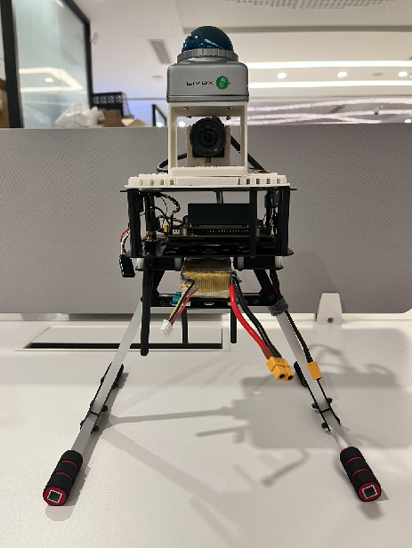
Instructions:
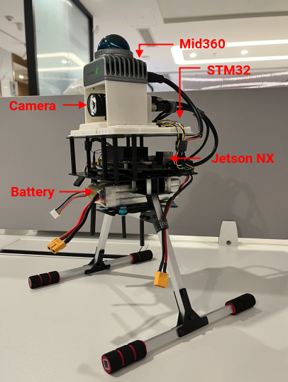
For time hardware synchronization: https://zhuanlan.zhihu.com/p/646137909 Alternative solutions: https://www.jianshu.com/p/d4b5cf3c1475 STM32 modifications: https://bbs.huaweicloud.com/blogs/367173
Hardware Synchronization Connection Scheme:
 Hardware synchronization principle:
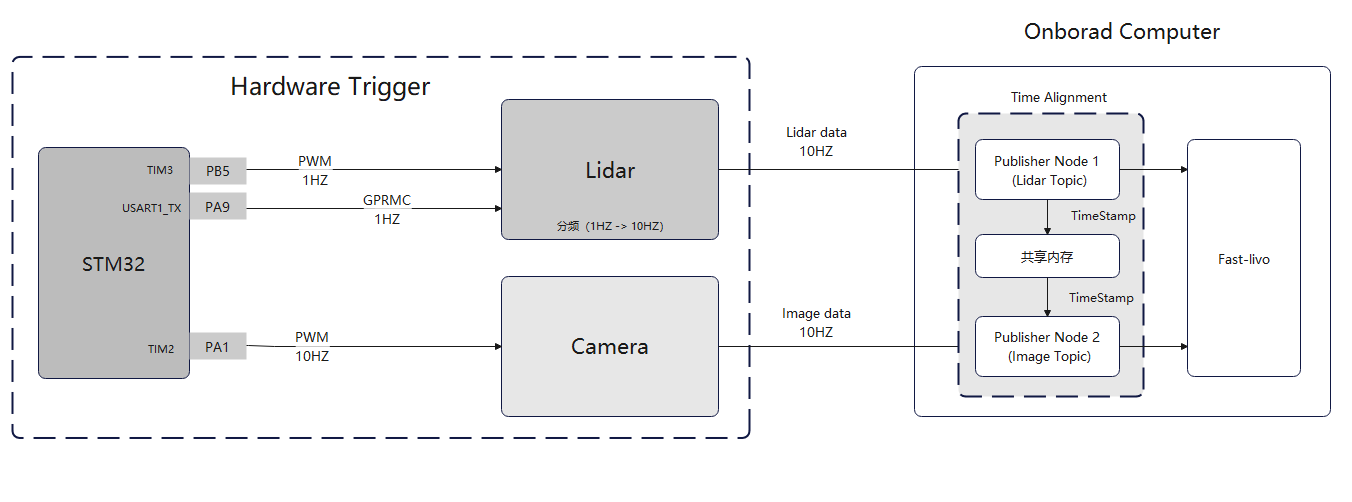
STM32 Board Instructions:
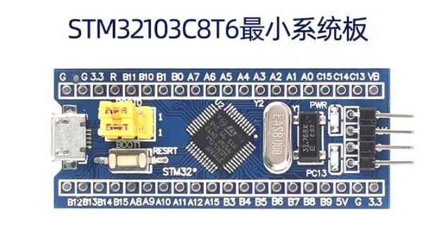
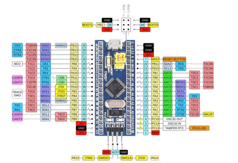
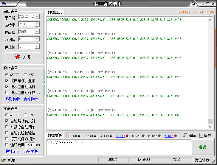
STM32 TX (PA9) output:
(You can connect PA9 and Gnd to a TTL to USB board, plug it into a computer and use a serial assistant to verify if the data output is correct)
Additionally, STM32 needs to be powered (5V or 3.3V, ensure the pins correspond correctly).
Supplement GPRMC data standard format:
$GPRMC,014600.00,A,2237.496474,N,11356.089515,E,0.0,225.5,310518,2.3,W,A*23
Content description:
field 0: $GPRMC, format ID, indicating the recommended minimum specific GPS/TRANSIT data (RMC)
field 1: UTC time, format hhmmss.ssss, representing hours, minutes, seconds.milliseconds
field 2: Status A: positioning success V: positioning failure
field 3: Latitude ddmm.mmmmmm degree format (zero-padded if leading digits are missing)
field 4: Latitude N (North) S (South)
field 5: Longitude dddmm.mmmmmm degree format (zero-padded if leading digits are missing)
field 6: Longitude E (East) W (West)
field 7: Speed (also 1.852 km/h)
field 8: Course over ground, degrees (2D direction, equivalent to 2D compass)
field 9: UTC date DDMMYY day, month, year
field 10: Magnetic variation (000-180) degrees (zero-padded if leading digits are missing)
field 11: Magnetic variation direction E = East W = West
field 12: Mode, A = automatic, D = differential, E = estimated, N = invalid data (protocol 3.0 content)
field 13: Checksum
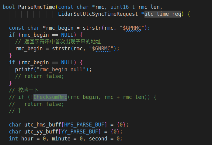
Note: In Fast-LIVO, the checksum here is fixed in STM32, and the checksum function is disabled in the Aiva camera driver (which can cause data corruption or jumping values). In this project, this data is directly transmitted to the Mid360 LiDAR, processed by the LiDAR firmware. We cannot modify the LiDAR firmware, so the checksum here must be restored as required.
Original LiDAR SDK driver:
STM32 modifications:
vu16 varl=0;
vu16 var_Exp=0;
vu16 global_time;
char snum[7];
vu16 shorttt=0;

char gprmcStr[7]="$GPRMC,";
int chckNum=0;
char chckNumChar[2];

int ss=0;
int mm=0;
int hh=0;

unsigned char result;
int i;
int checkNum(const char *gprmcContext)
{
    if (gprmcContext == NULL)
    {
        return -1;
    }

    result = gprmcContext[1];

    for (i = 2; gprmcContext[i] != '*' && gprmcContext[i] != '\0'; i++)
    {
        result ^= gprmcContext[i];
    }

    if (gprmcContext[i] != '*')
    {
        printf("No '*' found in the string.\n");
        return -1;
    }

    return result;
}

char value_1[100]="";
char value_2[100]="";
char value_time[10]="";

char test[100]="$GPRMC,004015,A,2812.0498,N,11313.1361,E,0.0,180.0,150122,3.9,W,A*";
void TIM3_IRQHandler(void)
{
    if (TIM_GetITStatus(TIM3, TIM_IT_Update) != RESET)
    {
        TIM_ClearITPendingBit(TIM3, TIM_IT_Update);
        LED1=!LED1;
        TIM2->CNT=TIM2->ARR/2;
        PCout(13)=0;
    }

    if(ss<59){
        ss++;
    } else {
        ss=0;
        if(mm<59){
            mm++;
        } else {
            mm=0;
            if(hh<23){
                hh++;
            } else {
                hh=0;
            }
        }
    }

    sprintf(value_2, "%s%02d%02d%02d%s", gprmcStr, hh, mm, ss, ".00,A,2237.496474,N,11356.089515,E,0.0,225.5,230520,2.3,W,A*");
    strcpy(value_1,value_2);
    chckNum = checkNum(value_1);
    sprintf(chckNumChar, "%02X", chckNum);
    printf("%s", value_2);
    printf("%s\n", chckNumChar);
}
Mid360 Wiring
Mid360 wiring sequence:
(Interface type: M12)

Where:
- Pins 4, 5, 6, and 7 connect to the RJ45 port's TX+, TX-, RX+, and RX- for point cloud data transmission
- Pins 1 and 2 connect to the power supply positive and negative terminals (voltage range: 9~27V)
- Pin 10 connects to the STM32's PA9 pin to receive GPS time synchronization information
- Pin 8 connects to the STM32's PB5 pin to receive a 1HZ PWM signal

The calibration origin of the Mid360 is at the top of the camera:

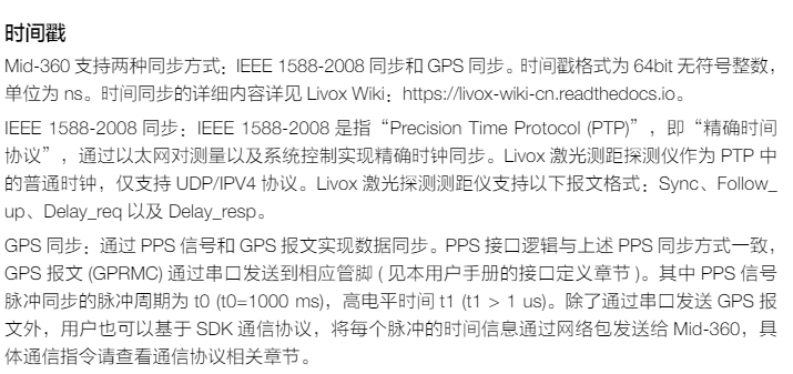
The integrated navigation module only connects the GPRMC-Tx output pin to the LiDAR, while the PPS second pulse is provided by the microcontroller. The camera trigger pulse is also provided by the microcontroller's frequency divider. The absolute time of more than one second for the camera and LiDAR is provided by the integrated navigation (the LiDAR frame already has GNSS absolute time over one second), and the time below one second is aligned to the microcontroller's second pulse.
- Supports multiple cameras and multiple LiDARs, with adjustable camera frequency.
- Time synchronization precision is limited by the micro
controller's clock precision but is simple and effective for real-time operation.
- There is a power-up time error for the system since the microcontroller's second pulse starts at system power-up, causing a small power-up delay, unlike the integrated navigation's second pulse aligned with the atomic clock.
- There is an error with the integrated navigation GPRMC absolute time because the microcontroller's second pulse starts at power-up. However, if absolute time alignment is not required, it does not affect the operation.
This hardware time synchronization device can be optimized: receive GNSS signals or use an NTP server to align with absolute time, controlling the second pulse and camera trigger pulse in the absolute time domain.

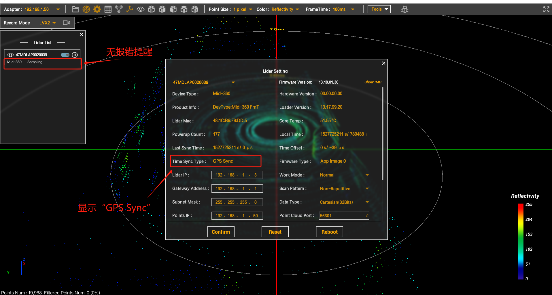
Standard for successful synchronization, as shown below:
LivoxViewer display
Camera Wiring
MV-CA013-21UC parameters:
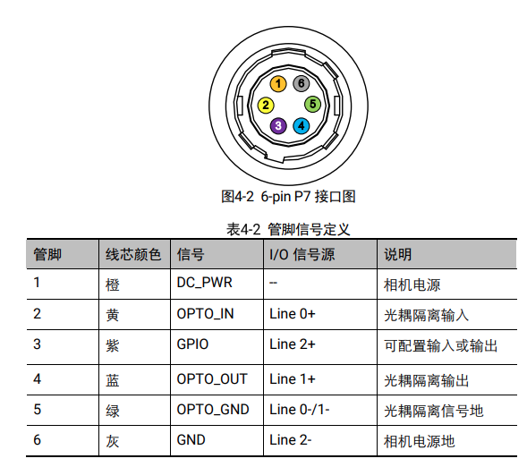
Required cable:
Basler camera 6-pin trigger cable, mainly for obtaining the PWM signal externally to trigger the camera.

Where:
- USB connects to the Jetson NX's USB 3.0 port (for data transmission and power supply)
- Pin 2 connects to the STM32's PA1 pin to receive an external 10HZ PWM signal
Pre-configure the camera using the MVS client to change the camera configuration to external hardware trigger mode. Refer to the camera user manual for details.
Complete hardware wiring diagram:

You can design your own mount or refer to the official guide.