RF switch characterization - WCP52/docs GitHub Wiki
Some of our input circuitry (in particular, the logarithmic detector) is expensive, and some, we want to be well matched between channels. Because of this, we chose to use an RF switch directly after the primary input filters to multiplex the two inputs onto one input frontend.
Our frequency range spans from 1 kHz to 200 MHz, which makes it difficult to switch directly. 200 MHz is too high for most monolithic analog switches, and 1 kHz is too low for a PIN diode network. It is possible to split the frequency into two bands and switch these individually, but we selected a simpler solution: a DC-coupled RF switch, which would work down to 1 kHz easily.
We had one extra requirement, which is that the switch must be an ''absorptive'' switch rather than reflective: when switched 'off', it must apply proper termination to the signal rather than just becoming an open or short. This is because both inputs connect to the same system, and reflections at one input port could cause disturbance to the other.
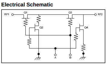
The switch we selected is the MASWSS0162 from M/A-COM Technology Solutions, which is a gallium-arsenide FET switch that is DC-coupled and rated to 2.5 GHz. The exceedingly high upper frequency gives a nice bonus: isolation is unusually good at low frequencies: above 60 dB within our range.

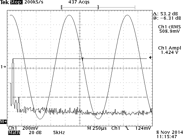
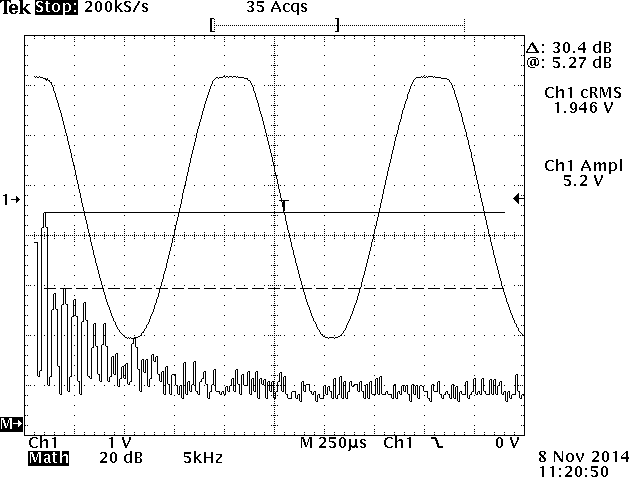
Because of the unconventional application, we had to properly test the switch under two conditions: low frequency, and high amplitude. The following are oscilloscope plots of the switch output when switched 'on' and fed 1 kHz sinusoids at varying amplitudes; FFTs are included to show distortion:


With the switch 'off', output waveforms could not be detected by our equipment, even at the full 2 V rms input amplitude. Detecting these would likely require a shielded, low-noise test environment with a filtered preamplifier.
The MASWSS0162 draws about 500 uA of gate current at the recommended -5V bias; 10k pulldowns to ground are sufficient for the zero-bias case. We will use a simple transistor switch to pull the relevant gates to the -5V rail, with a series 220 ohm resistor (0.1V drop) to protect against excess current draw in the case of elevated temperatures or unusual signals. We will also decouple the gate to ground to prevent fast-rising signals from switching the device.