4. Circuitry - Vijay-P/pill-dispenser GitHub Wiki
Hardware: Parts
| Components | Purpose |
|---|---|
| Raspberry Pi Model 3 B+ | Web Controller Host, Master |
| Adafruit Metro Mini | Hardware Input, Slave |
| NEMA 17 Stepper Motor 4.8V | Drive Medication Carousel |
| Limit Switch | Home Medication Carousel |
| Mini Low Speed Motor 3V/50 RPM | Drive Foam Dispensing Mechanism |
| Red LED or Laser Diode | Medication Drop Detection |
| Photoresistor | Medication Drop Detection |
Circuit Board
First Attempt
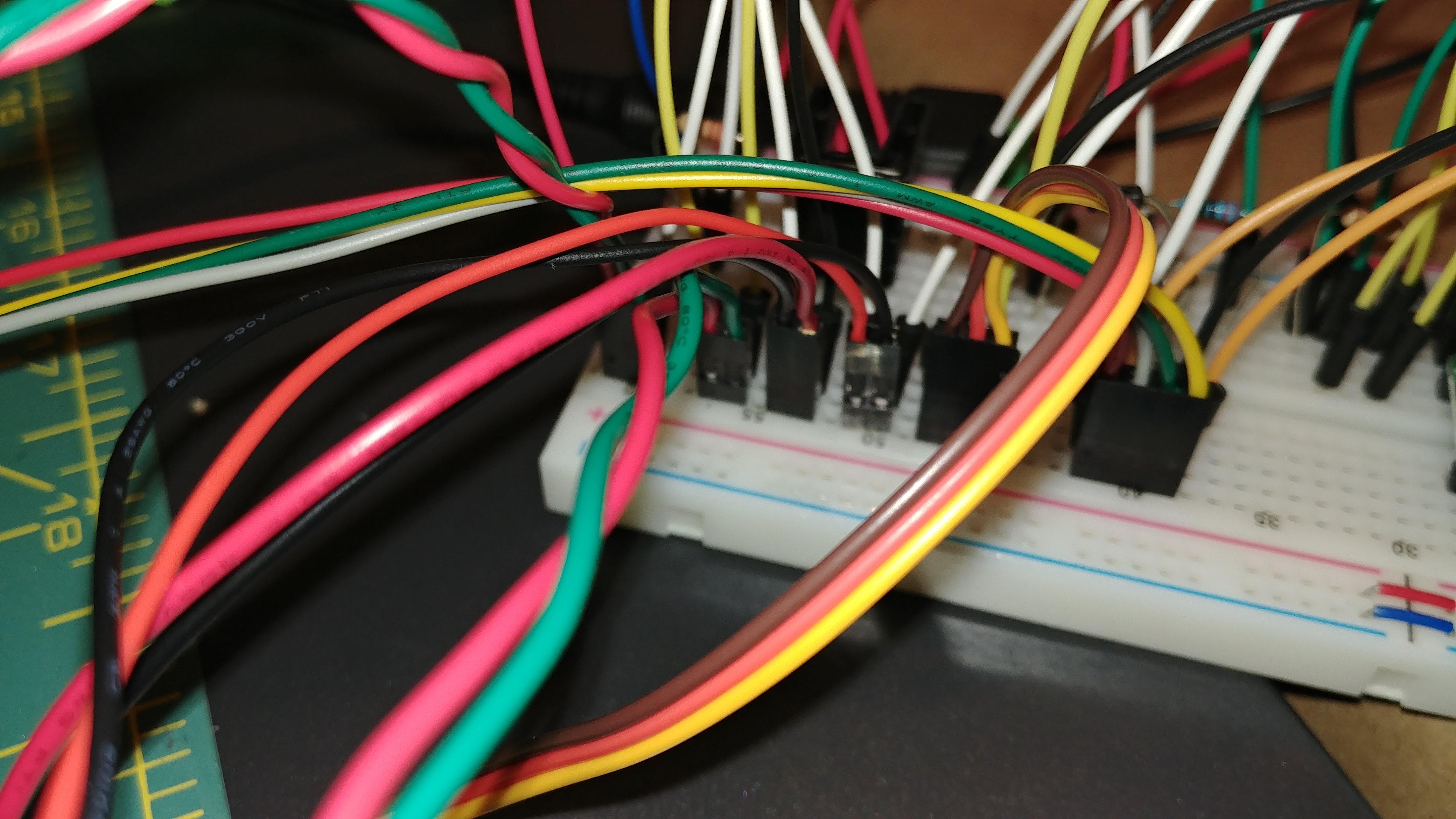
 Our first attempt used the long flexible jumper cables. The circuit worked, but was incredibly messy. When wires got disconnected it was impossible to debug.
Second Attempt
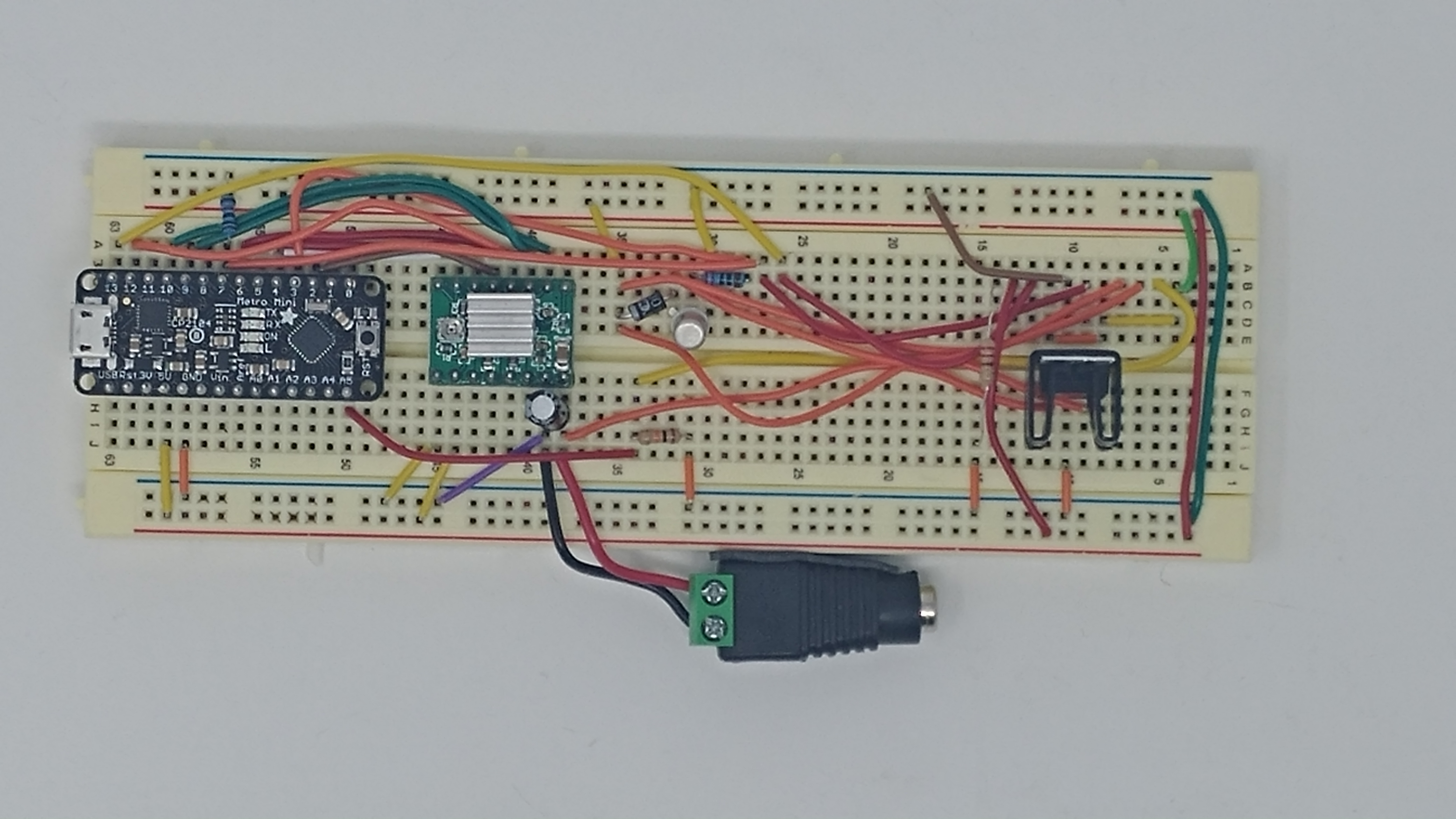
 Much easier to test with a multimeter.
Components
For the circuit, we have various components that when put together, create pillar. For the main rotating section, where the user would be able to store all pills, we use a stepper motor. The stepper motor can be controlled at full steps, half steps and micro steps in order to get the perfect angle of rotation in order to fall directly into the dispensing mechanism. The circuit for this is shown below.

In order to actually control a stepper motor with the arduino, we need to use a stepper driver. Specifically the A4988 Stepper Driver. The A4988 is a microstepping driver for controlling bipolar stepper motors. The driver supports the following resolutions: full-step, half-step, quarter-step, eighth -step and sixteenth-step. It also consists of a potentiometer for adjusting the current output.
Most of the pin connections are mostly straight forward. We do, however, have two pins that are vital in controlling the behaviour of the stepper motor. The DIR and STEP pins are used to control the direction and step angle of the stepper motor respectively. The reset pin is useful to be able to set a distinct home position.
For the dispensing mechanism, we use a DC motor to be able to drive 2 gears that dispense pills one at a time. For this, we used the following circuit.
 We need to use a few additional components in order to ensure proper working of the system. We use a 2N2222 transistor along with a 1N4001 diode. The transistor acts like a switch, controlling power to the motor. The DC motor uses more power than an Arduino digital output can handle directly. In such cases, we can use the transistor as a switch with low current from the arduino to drive the motor. The diode is used to make sure that current only flows in one direction. When power to the motor is cut off, there can occasionally be a reserve voltage that flows through the circuit. In such situations, the diode prevents this reverse voltage from flowing.
In order to make sure that pills do not flow freely, we had to implement a sliding door that would block the passage from the container to the pill dispensing mechanism. For this application, we used a servo motor.

A servo motor shaft rotates based off of a control signal. It runs on the basis of Pulse Width Modulation (PWM) to turn the shaft either clockwise or anticlockwise. In our setup, the servo was used just to cover the hole to prevent pills from dropping down.