xchip lab 4 - VCSFA-MARS/ThinSat-Program GitHub Wiki
To perform this lab you will need:
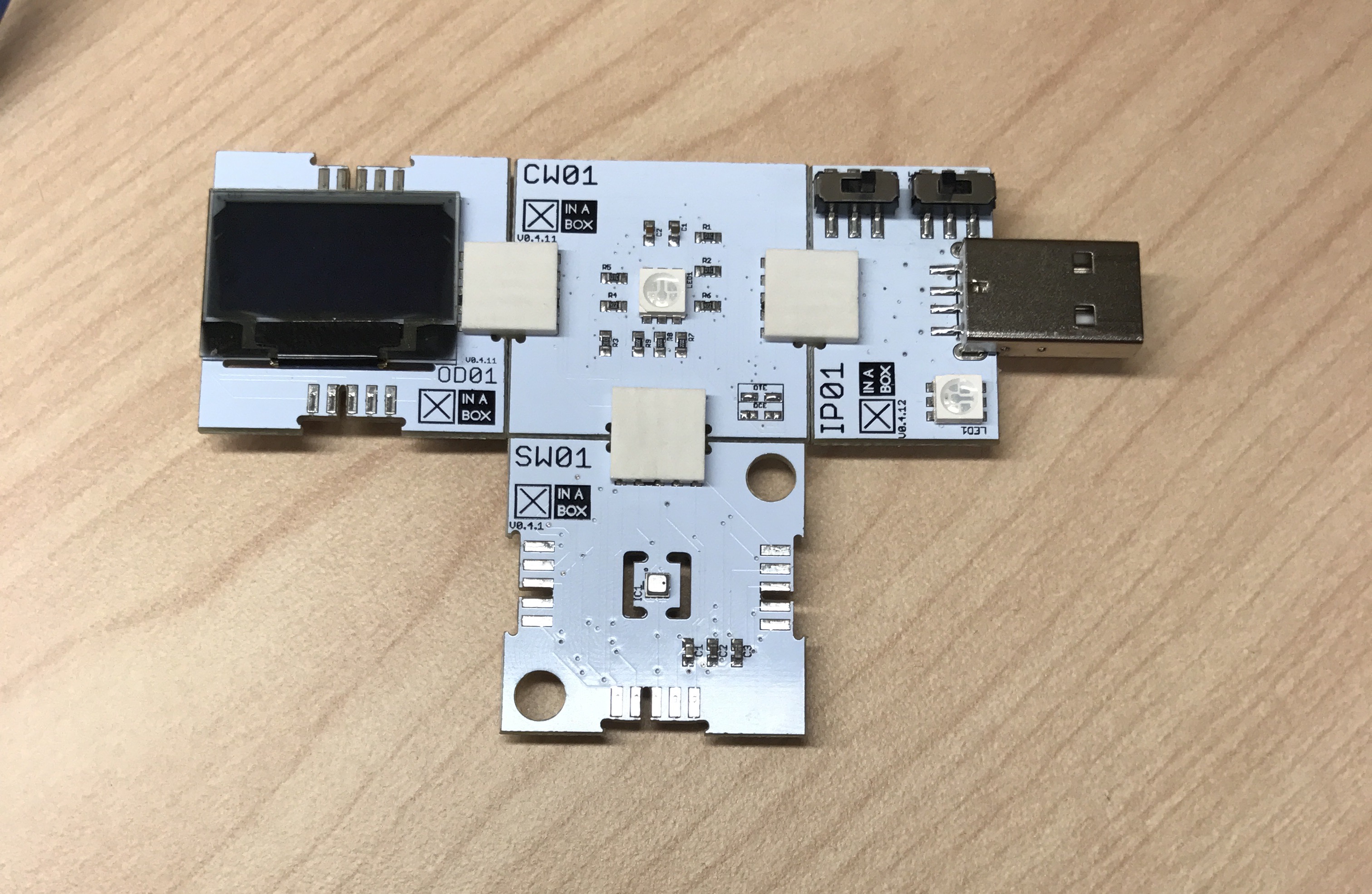
- IP01 xChip- USB module
- CW01 xChip- WiFi module and processor
- OD01 xChip- OLED display module
- SW01 xChip- Humidity, Pressure, and Temperature Sensor
- 3 Connector pieces
The goal of this lab is to familiarize you with serial monitor connections and basic troubleshooting for said connection. The serial monitor connection is tricky to establish and easy to break, so care should be taken.
Click your pieces together using the connector pieces. Again, the xChips can be plugged together in any configuration, and the xSystem will work no matter the configuration. This is the same setup as lab 3.
To open the serial monitor select the magnifying glass icon in the upper right corner of the Arduino IDE.

This window is called the Serial Monitor and it is part of the Arduino IDE software. Its job is to allow you to both send messages from your computer to your xSystem (over USB) and receive messages from the xSystem.
The xSystem can listen and talk to the Arduino IDE, but not at the same time.
As we've mentioned in previous labs, in order to upload code to your xSystem you have to have your switches in a specific configuration.
Upload mode: Switches B and DCE
This sends information to the xSystem from the Arduino IDE
Communication mode: Switches A and DCE
Communication mode is new to us, and is used to send information from the xSystem to the Arduino IDE.
Notice the LED colors while the code uploads. During upload, IP01 will rapidly flicker blue, and CW01 will be solid green, this is true for every code.
Verify and upload the following code onto your xSystem.
/////////////////////////////////////
// Establish Serial Monitor Connections
// Take Temperature Measurements and display on Serial Monitor
// Uses SW01, CW01, OD01 and IP01 xChips
// Written by E. Bujold
/////////////////////////////////////

  #include <xCore.h>     //This library allows us to use the CW01 processor
  #include <xOD01.h>     //This library allows us to use the OD01 screen
  #include <xSW01.h>     //This library allows us to use the weather sensor

//Define hardware connections to the LED colors.
  const int RED = 12;
  const int GREEN = 13;
  const int BLUE = 5;

void setup() {
  Wire.begin(2,14);     //Starts the xChips talking to each other
  Serial.begin(9600);   //Define serial monitor connection parameters
  SW01.begin();         //Turn on the weather sensor
  OLED.begin();         //Turn on the OLED Screen

//Define use of LED, output color
  pinMode(RED, OUTPUT);
  pinMode(GREEN, OUTPUT);
  pinMode(BLUE, OUTPUT);

//Initial state, Turn all LEDs off
  digitalWrite(RED,   LOW);
  digitalWrite(GREEN, LOW);
  digitalWrite(BLUE, LOW);

//These instructions will display on the OLED screen
//Flick the switch from B to A and then open the Serial Monitor
  OD01.println("Flick the switch");
  OD01.println("from B to A");
  OD01.println();
  OD01.println("Open the Serial");
  OD01.println("Monitor and type 'go'");

 while (Serial.available() == 0) {
 //Blink the red LED until connection is esablished
    digitalWrite(RED, HIGH);  // Turn on
    delay(500);               // Stay on for dwell time
    digitalWrite(RED, LOW);   // Turn off
    delay(500);               // Stay off for dwell time
  }

// Type any message into the Serial Monitor to establish communication
  Serial.readString();
  digitalWrite(BLUE, HIGH);    //blue light will turn on after the connection is established
  Serial.println("Connection Established");

//These new instructions print to the LED screen
  OD01.clear();                 //Clear LED screen
  OD01.set2X();                 //Set font size
  OD01.println("Connection");
  OD01.println("Established");
  OD01.set1X();                 //Set font size
  OD01.println();               //Print a blank line
  OD01.println("Flick the switch back");
  OD01.println("to B to upload code");

//This prints to the serial monitor
  Serial.println("~~~~~~~~~~~~~~~~~~~~~~~~~~~~~~");
  Serial.println("~        XinaBox SW01        ~");
  Serial.println("~~~~~~~~~~~~~~~~~~~~~~~~~~~~~~");

delay (1000);   //Dramatic pause
}

void loop() {
// Measure Temperture and Humidity, then print results to Serial Monitor

  SW01.poll(); //Read and calculate data from SWO1 sensor

  Serial.print("Humidity: ");
  Serial.print(SW01.getHumidity());
  Serial.println("%");

  Serial.print("Temperature: ");
  Serial.print(SW01.getTemperature_F());
  Serial.println(" Degrees");

  Serial.println("~~~~~~~~~~~~~~~~~~~~~~~");    //Decorative divider

  delay(1000);
}
Once the code is uploaded, you will notice a red blinking light on the CW01 xChip and some instructions on the OLED screen. The blinking is provided for extra clarity but is only available for this code.
Follow these instructions to establish a serial connection:
- Flick the switch from B to A

- Open the Serial Monitor
- Type
gointo the serial monitor.
An established connection in this lab will have the following characteristics:
- The OLED displays "Connection Established"
- The CW01 has a solid blue light
- The IP01 has a solid blue light
- The serial monitor will display fresh data
If at any point the connection is broken (some of the TRY IT exercises will intentionally break the connection), follow the instructions in the "Rebooting the Chips" section.
While the blue light is on, the xSystem is connected to the serial monitor. You can close the serial monitor screen without disrupting the connection.
TRY IT:
- Establish the connection to your xSystem.
- Open and close the serial monitor screen.
Notice as the serial monitor was opened and closed the IP01 LED turned on and off.
Serial connections are unfortunately easy to break. When your xSystem encounters a problem with the connection it will stop sending data and notify you with its LED.
TRY IT:
- Establish a connection and open the serial monitor
- Put your device in 'upload mode' (switch B) without closing the serial monitor.
This breaks the connection. The CW01 LED will turn green notifying you of a problem, no more data will be sent to the serial monitor.
- Close the serial monitor. It will reboot the xSystem.
Whenever the CW01 light is green, you need to reboot the chip to reestablish connection.
Practice resetting your xSystem a few times. It's an important skill that we will be using throughout this lab and in future labs.
TRY IT:
- Put the chip in 'upload mode' (switch B).
- Open a serial window, don't type anything.
- Close the serial monitor to trigger an xChip reboot
With this program it will make the CW01 LED blink red. In future labs, after a reboot, the LED will simply turn off.
You can reboot at any time, in any lab with this method. If your device is already in 'upload mode' (switch B), just open and close the serial monitor.
It is important that the serial monitor is opened AFTER the switch is flicked from B to A. If you open the monitor first you will get gibberish on the monitor.
TRY IT:
- Reboot the xSystem and wait for the blinking red light. Keep the device in 'upload mode' (switch B).
- Open the serial monitor.
- Switch to 'communicate mode' (switch A).
You will see gibberish on the screen. The connection was not established properly. Reboot your xSystem.
If you switch to 'upload mode' (switch B) when the serial monitor is closed, the xSystem won't notice the connection is broken, because it isn't communicating with the IDE. It's a risky trick that may not always work, but as long as you switch back to 'communication mode' (switch A) before attempting to communicate, there shouldn't be a problem.
TRY IT:
- Establish a connection.
- Close the serial monitor. IP01 blue LED will turn off.
- Switch to 'upload mode' (switch B) and wait for a few seconds.
- Switch back to 'communication mode' (switch A).
- Reopen the serial monitor. IP01 blue LED will turn on.
Continue to Lab 5!
Home | Getting Started | Code Tutorials | Troubleshooting | xChip Glossary
For technical support please email: [email protected]
![]()