Hardware - Uberibsen/AstralisLEDSign GitHub Wiki
The components used to make the sign work is as following:
- Arduino Nano
- WS2812B adressable RGB LED strip
- 7-segment display
- 74HC595 Bit Shift Register
- Push button
- Potentiometer
The following pages will further describe the individual components, how they work, and how they are used.
WS2812B RGB LED strip
The core of this project is to be able to light the sign itself in different kinds of lighting sequences. The WS2812B addressable LED strip comes in several models that differ in size, sealant, or LED density. For this project, I used a density of 60 LED's per. meter with no water resistance since it is going to be used indoors during matches. The strip is glued with double-sided tape directly onto the board. It is fed with 5v directly from the power bank supplying the power for all components in this project, as well as a 1000 μF capacitor to spare the first LED's on the strip for a potential surge of power, frying them. You can read more here.
7-segment display
This display has nothing more than 8 LED inside. It is separated into segments that are named as a,b,c,d,e,f,g, and DP and can be lit in different combinations to represent the Arabic numerals as well as a dot (DP). This GIF shows how each LED is addressed:

In order to quickly identify which lighting sequence the sign is running, the number can be read out rather quickly as it is located next to the sequence button on the back. When the sequences loop, the number will start back at '1' to indicate that the sequence has reset. As a failsafe, the display is programmed to show an 'E' if an error should occur.
The number shown is determined by how many bits are sent via the 74HC595 bit shift register, which will be elaborated on in the next section.
You can read further into the 7-segment displays as well as other uses on this link.
74HC595 - Bit Shift Register
Normally, in order to control every LED in the 7-segment display, it would require each pin to be connected to the Arduino. This way, you would quickly run out of pins if you were to have multiple digital pins in use. This is where the bit shift register comes in handy. With a bit shift register connected in series, we can accomplish the task of controlling up to 8 LEDs by only using 3 I/O pins. And not just this; you can save even more pins the more shift registers you have chained multiple together if you'd like to control more displays. For this project, a single digit is enough.
The 595 has two registers (which can be thought of as “memory containers”), each with just 8 bits of data. Depending on what data you send to the 595, the data will first be stored and only transferred to the output pins once the 595 is latched.
You can read a more in-depth explanation about the 74HC595 in this detailed guide.
Sequence button
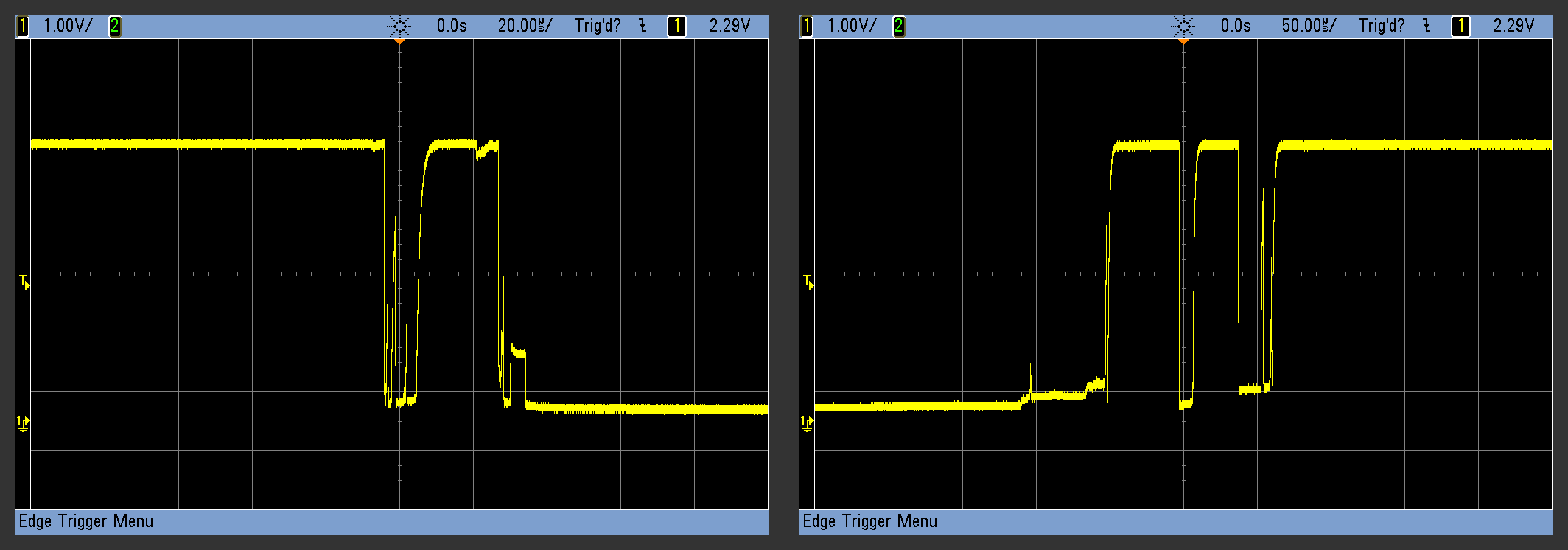
The idea of the sign itself it that it stores multiple lighting sequences, which you can switch between with a simple push-button. The main idea is that by a single push, the sign should go to the next lighting sequence once the button is pushed and released. Buttons come in many sizes and shapes, but many of them share the same issue in regards to sending a HIGH or LOW signal. This is commonly referred to as a 'bouncing' signal where the signal quickly jumps up and down multiple times in a short amount of time (typically a few milliseconds). This can be countered by implementing what is called 'debouncing.' The below image is an example of a button being pushed and released, bouncing the signal before settling.

Debounce
When you physically press a normal push-button, two pieces of metal come into contact with each other. If these two tiny sheets of metal aren’t perfectly flat or perfectly aligned (and they’re not), then they can make and break contact a few times before being firmly enough squished together that they’re always conducting. To a microcontroller, the button appears to be pressed many times for extremely short durations when you think you’ve just pressed it once. Debouncing is all about making sure that you and the microcontroller agree about when a button push or release event happened. This is how a button push is registered without any form of debouncing.

The simplest hardware solution, which is shown in the image above is to debounce with a 10K ohm resistor and a 1μF capacitor. For this project, the debouncing feature is critical for the reason being that the sign has multiple lighting sequences stored. If the button registers multiple 'pushes' in one, the sequences would quickly cycle through, resulting in an incorrect cycle.
For a more detailed explanation you can read further here.
Brightness control
On the far left on the control interface, it is possible to control the brightness of the LED's. This is done by using a potentiometer, which acts as a variable resistor and commonly used to control electrical devices such as volume controls or, in this case, lighting. Depending on how much the potentiometer turned, the resistor is only letting a part of the total current, though, which can be read via an analog signal. How this signal is read and used will be further explained in the software section.
For a more detailed explanation on how a potentiometer works you can read more here.