RFID Reader - Toolauth/wing-combo GitHub Wiki
[!CAUTION] This section is incomplete.
Core Functionality
Read a user's RFID card to request if they are authorized to use the tool.
Simple Use Explanation
The end-user will swipe their RFID badge over a connected reader device, and that will prompt an authorization request to a remote server. A buzzer and LED give basic feedback for the authorization. The aforementioned server can then enable the tool (in the case of the wing-combo, the RFID read and tool-control are managed by the same board).
Implementation Details
Select & Connect RFID reader daughter board
For this project, the RFID reader was selected as a cheap, off-the-shelf retail board centered around the PN532 chip. This chip is supported by ESPHome, is connected via I2C, and widely available online in simple breakout boards.
We just buy our PN532 boards from Amazon. Here is a pre-formatted Amazon search. We get the seemingly ubiquitous red-square boards, but any that connect a PN532 via I2C over a 4-pin JST connection should work.
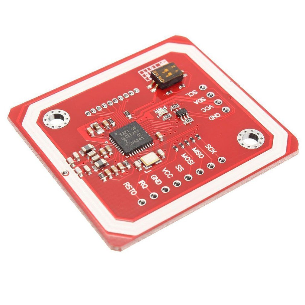
The 4-pin JST connectors that these boards use are really hard to put in backwards (provided they are soldered in right). You can use either of the two I2C connections on the wing-combo board; but they are also the only connectors where the 4-pin JST should fit on the wing-combo board.
I2C pinout
We connected the pins in this order on the 4-pin JST 2.0 connector:
- Ground [GND] -------> black wire
- 3.3 volts [3V3] -------> red wire
- SDA ------------------> white wire
- SCL ------------------> green wire
important to note: wire color will vary
As far as we could tell, this is the most-common pin order for I2C connections. Our red PN532 boards have their connections in this order, and made the soldering smooth sailing. However, you'll want to verify this and any DIP switches you may need to flip in order to have the PN532 working properly in I2C mode.
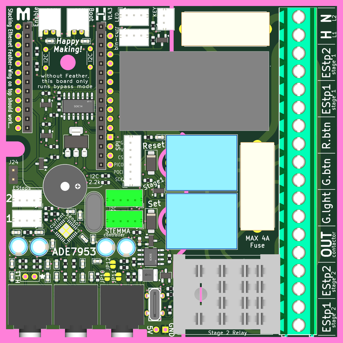
The location of both JST connectors for I2C communication are shown below. The RFID card reader can use either connector.
logical diagram
The image below describes the RFID reader section of the firmware, as used by the board's creators in ESPHome. Of course, other control structures could be used; but this is the one that we work with. Use at your own discretion.
