Power Required - Toolauth/wing-combo GitHub Wiki
[!CAUTION] This section is incomplete.
This will explain how the device is powered.
Core Functionality
A single Power source for the tool and controller board. Branching power within a controller box can power the tool and the wing-combo board's operation from a single incoming wire.
Simple Use Explanation
On the wing-combo board, there is a sealed Cincon/CFM06S050-E transformer to power the low-voltage circuits and a set of mains-voltage relays to control the tool.
Sealed Transformer
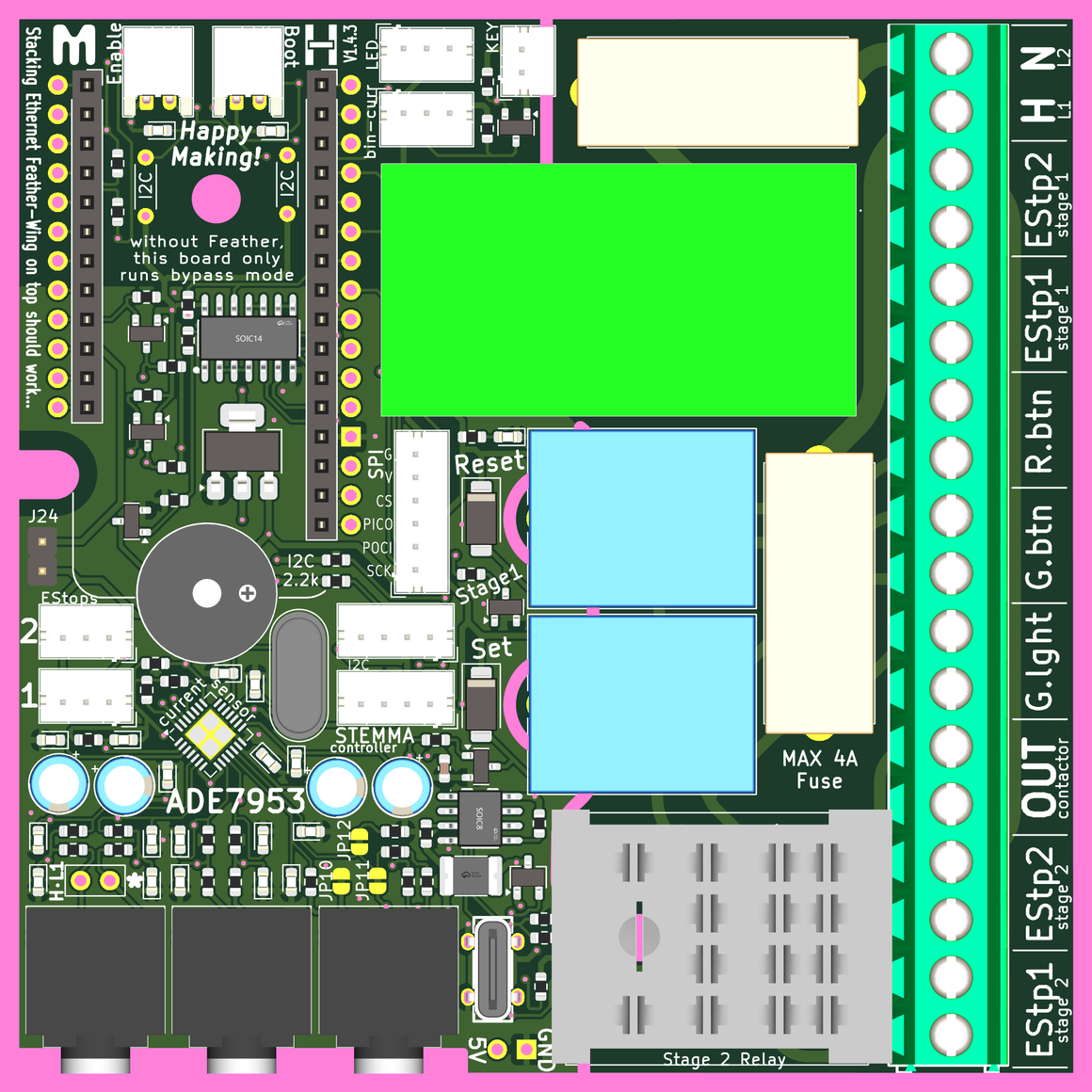
A Cincon CFM06S050-E 5 volt output transformer is used on the wing-combo board. It usually is not soldered into place by the board's fab-house and will need to be hand soldered when provisioning the board. There is only one orientation where the transformer will fit - 'above' the board, like all the other components.

Location of the sealed transformer is shown below:
5 Volts Available
There is one power-only female USB port on the board. This exists so that low-power daughter boards (perhaps for managing an e-paper displays) can be added without impacting the limited computing power of one microcontroller.

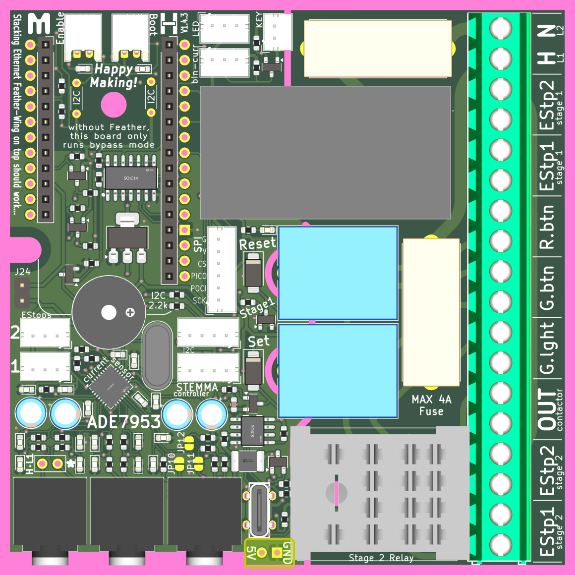
There is also a solderable conneciton for 5V and Ground, in case that is helpful. There is no forseen use for this, it is just good to have for the future...
Mains Input
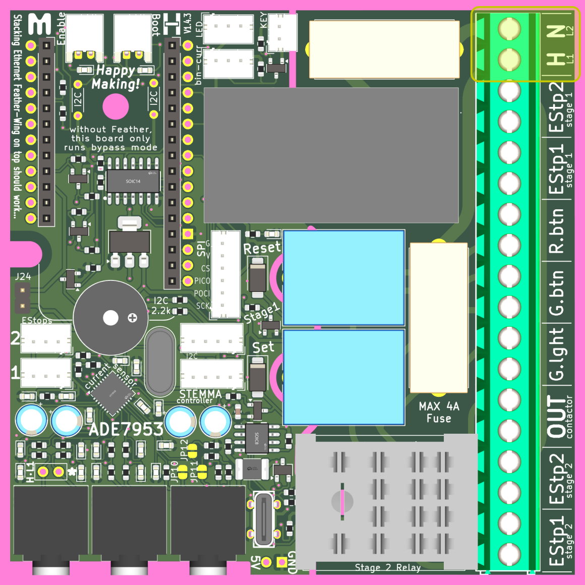
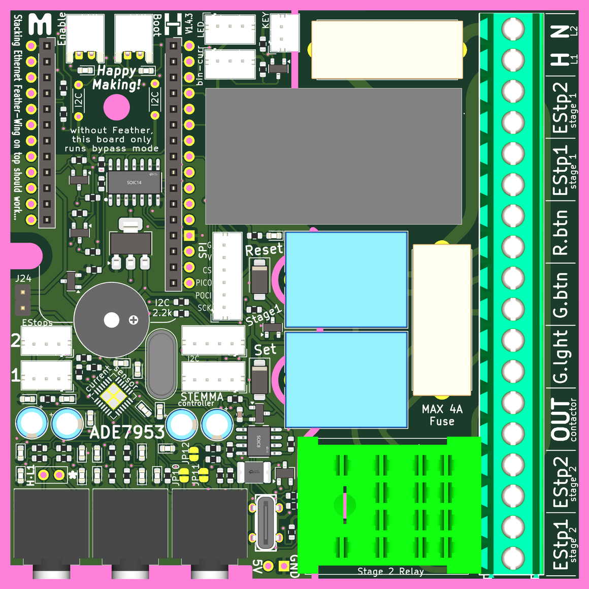
Power from the supply mains needs attached in the location shown below. The 'H' location is for the Hot wire (USA: Black/Red wire). The 'N' location is for the neutral wire (USA: White wire). for Two-phase power the L1 and L2 lines can input to these same locations indescriminately. Other localities will need to cross-reference these connections.
Power Fuses
Two 5x20mm fuses, no higher than 4 Amps, need places in these two fuse holders. They should protect the wing-combo board from any kind of over-current protection. You can use lower amperage fuses, so long as they have enough power for your needs. DO NOT shunt these instead of using fuses --> very dangerous!
Stage 2 Relay
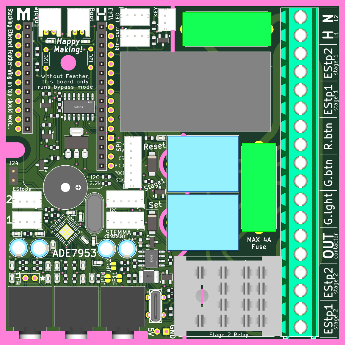
The 'stage 2' relay is an Omron MY2-02 relay, and these come in multiple variations with the same footprint. If you want to control a tool that runs at 110-120VAC, you can use the Omron MY2-02-AC110-120. If you want to use a tool with two-phase power (or in Europe), you can opt for the Omron MY2-02-AC220-240. These and any other same-footprint relay make this board very adaptable. Controlling tools that use three-phase power will require careful selection of this relay along with a compatable contactor.
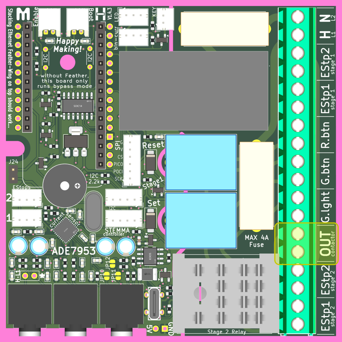
Contactor Output
The wing-combo board's primary output goes to control a contactor with mains voltage.
[!WARNING] Technically, you could operate a tool directly from the output shown below, but this is STRONGLY NOT RECOMMENDED, as it would pass all the tool's current through the wing-combo PCB, and it may blow fuses or other bad things...