Electric Current - Toolauth/wing-combo GitHub Wiki
[!CAUTION] This section is incomplete.
Core Functionality
Monitor the tool's use and status. A specialized chip and current clamp can track electrical current usage and more, with aa resolution of approximately 10 milliamps.
Simple Use Explanation
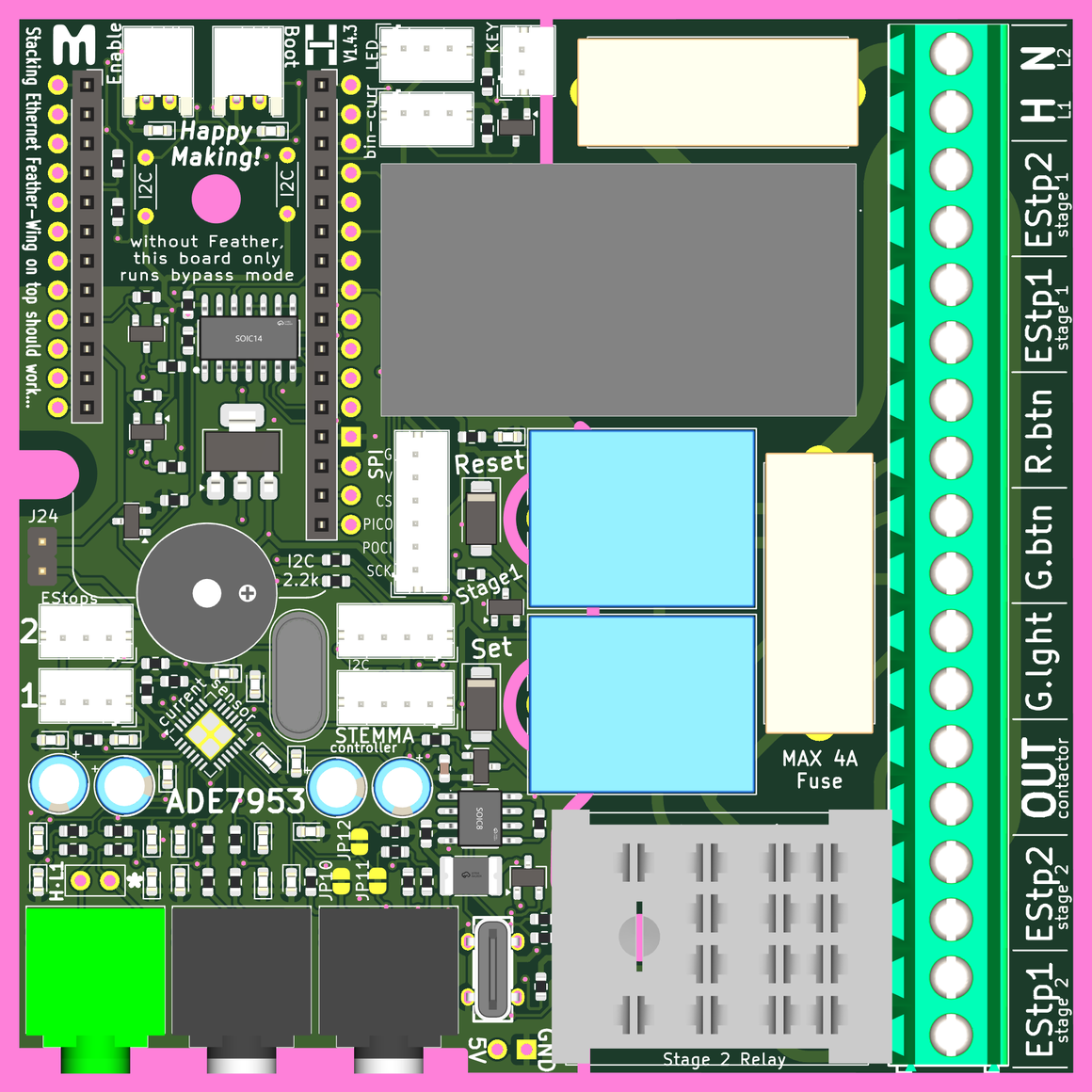
A dedicated chip, the ADE7953, continuously monitors the electric current used by the tool at varying intervals. This chip can measure accurately down to about 10 milliamps, which is a very good assessment of how much energy is being used. After a bit of initial calibration, that current monitoring is translated into a current_index or tool_amp_index that maps the current to one of several states describing the tool's operation. In the cardsystem/ESPHome firmware this index is then used as a central mechanism of controlling the wing-combo board's operation.
With regard to the varying intervals of measurement: When the tool is in operation, the current is tracked many times a second. When the tool is off, the measurements happen every few minutes (as a heartbeat status check).
The CT clamp sensor showm below pluggs into the 3mm jacks on the board [Hot/L1, is the primary]. A single [not both] current-carrying wire of the tool is then passed through the center of the clamp so that it can measure the electric current used by the tool itself. There are many variants of these clamps, but the only defining properties needed are an approximately appropriate Amps-to-Volts scale and the 3mm/0.125in jack.
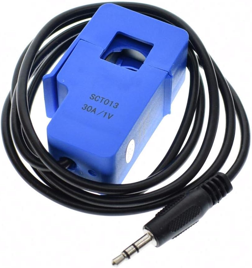
The CT clamp shown above will allmost-always plug into the Hot/L1 plug on the board. As this is the most common connection point there are also a pair of solderable connection holes, in case they are needed. However, we expect that the plug-in CT clamp will be much more common.
[!IMPORTANT] Everything below describes the cardsystem/ESPHome firmware the original creators use with this board. You may use it as inspiration for other applications, but the operation of the wing-combo does not strictly require this.
An Index to track Electric Current usage
The current sensor for the wing-combo is able to measure electric current usage very accurately. However, to trigger actions appropriate for each tool, ranges will be defined by certain cutoff values for different kinds of operation (more on setting these values, further down).
Index Range Definitions
For the current_index or tool_amp_index we need to think about 5 levels of current:
0: OFF - nothing turned on, and not in any active standby mode
1: Standby (think: controller on, motor not spinning)
2: Spinning (think: saw spinning, but not cutting wood)
3: Cutting (think: table saw is actively cutting wood)
4: Overload (think: table saw blade has jammed in a piece of wood)
The zones described above can be difficult to visualize over time, so a graph is presented below. The red line shown in the graph, represents how electric current may be used by a tool. We can better understand what is going on by exploring this at a few levels. Let's consider a compound miter saw for this example, as it tends to make it easier to wrap your head around.

First, the narrative version: Consider this brief narrative.
The saw is turned on and briefly left in standby - perhaps this means a light is on to aide in seeing what you're cutting. Then the user presses the switch that spins up the blade, before attempting a cut. Then they lower the blade into a piece of wood and make a cut. Without releasing the switch (the blade is still spinning) they raise the saw blade to stop cutting, and adjust the piece of wood. They start cutting again, and this time they can feel it overloading the blade, so they quickly ease out of the cut and let the blade spin down. After just a brief time, they fully turn the saw off.
Second, Look at points: Consider the saw's operation at each of the points in the graph, described below.
A: The tool is totally powered-off, so we see zero-current on our current sensor.
B: The saw blade is spinning, but not cutting anything. We can expect this state to have relatively even energy-needs. However, it is possible to see some "spikes" at the beginning or end of operation in this state.
C: The tool is actively cutting a piece of wood. The electric current needed by the tool goes up to provide more energy for the cutting process. This is needed to counteract the friction of making such a cut.
D: The tool returns to a state where it is spinning, but not cutting. This is nearly the same energy requirement as B for a healthy saw.
E: Another cut, which requires more power than the previous one.
F: The saw is really overloaded. The saw blade is slowing due to heavy friction from the cut: this is a near-stall. Perhaps the saw is trying to cut through a thick knot in the wood, or a hidden metal screw. The user realizes this and takes action to stop operation.
G: The saw blade has stopped spinning, and all that is powered on is an LED that is used to help illuminate the cut area. This is the standby state for our saw. Very minimal power usage.
H: The tool is totally powered-off, so we see zero-current on our current sensor.
Setting Index Thresholds
In setting up a tool, threshold values that delineate the operating ranges must be determined and set in the firmware. These values can be calibrated, so that they accurately reflect the electrical energy use of the tool, or they can be based of whatever the default gain of the chip-clamp-system happens to be. Measuring this gain is often technical, requires a bit of math, and some extra hardware: a known electrical load for testing.
Process for Finding the Index Thresholds
- Hook up the tool, and load the cardsystem/ESPHome firmware.
- Connect the wing-combo to your local network, and ensure that it shows up in a local installation of Home Assistant (for viewing the current readings in near real-time).
- Perhaps with a friend: slowly pass the tool through the index states 0-3 and note the current used at each of these states.
- Skip overloading/ stalling your tool: just make the tool's top-rated current the
cutting_highEndvalue.
- Skip overloading/ stalling your tool: just make the tool's top-rated current the
- Based on your observations, choose values that make sense for the following
substitutionsin the firmware.standby_lowEnd: "0.05" # smallest current of a standby mode running_lowEnd: "1.00" # smallest current when motor spinning cutting_lowEnd: "1.50" # smallest current when making light cuts cutting_highEnd: "2.50" # largest current before motor stall - Reinstall the firmware, and see that it reports the tool's status as desired. Repeat the steps above to tweak these values as necessary.
Calibrating the Current Measurements
[!TIP] The system will operate just fine without the calibration step described below, but values will not reflect reality.
Calibrating the current measurements requires almost the same process as described above, but you must set a calibration value that is a simple linear gain multiplier:
  # The following is the linear calibration for current-based actions
  calibration: "1.00" # multiplier to calibrate current draw
Essentially, you need to know how much current is actually being drawn to derive this calibration value. You can either use a known-load (like a favorite box fan or specifically calibrated tool) or you can use a second current-clamp meter to measure the actual current used by the tool.
Just like the process for finding the index thresholds above: test, measure, input the value into firmware and test again. Adjust as needed.