Communications - Toolauth/wing-combo GitHub Wiki
Core Functionality
Communicate with local and remote systems for all functions. Using a range of communication protocols, the wing-combo and its microcontroller communicate with servers and subsystems for complete functionality.
Simple Use Explanation
Mostly the wing-combo board communicates to servers over wifi, with HTTPS requests in both directions.
When the wing-combo board is in a control box, it uses a few other communication standards to control attached hardware. Mostly I2C (for chip-to-chip) and Digital I/O for simpler components.
Protocols Used
[!NOTE] Technically, only I2C and Digital I/O must be used with the wing-combo wholly, or in part, as described below. The rest of these protocols are subject to the firmware used, but what is below describes use in the cardsystem firmware.
Wifi
The wing-combo uses Wifi as it's main communication channel with the server. All of the communication over wifi is done with API requests (instead of MQTT) as the API requests offer more feedback to sender and reciever for every call, and the full power of web tools to track and diagnose.
ESPHome and Home Assistant use API calls natively to interact and the firmware, as written in in the cardsystem repo. These allow for event driven automations, within their ecosystem.
As the communication is done via HTTPS requests, several benefits are used in this communication:
- HTTPS ensures TLS encryption of the messages between sender/reciever
- Data is enclosed as JSON in the body of the message, rather than the URL
- Common & simple tools, such as postman, allow for testing these requests
Bluetooth
Bluetooth is not used with the wing-combo board. (Even though it is availble with most every ESP32 based board.)
I2C
The ADE7953 current sensor chip uses I2C to communicate with the microcontroller. This is hardwired into the board itself, and cannot change.
The RFID reader breakout boards use I2C to communicate with the microcontroller, as described in the full firmware that the original creators use with the board (in the cardsystem repo). These RFID readers could be switched to SPI, if needed for some reason.
There is one unused 4-pin JST header for I2C communication on the wing-combo board, avaiable for unknown future expansion.
SPI
There is one unused 6-pin JST header for SPI communication on the wing-combo board, avaiable for future expansion. One possible use the board's creators envisioned for this was to add e-paper displays for more visual feedback to users.
USB
The Microcontroller's USB port is the primary programming interface for the board. It can also be a useful venue for logging while setting up the microcontroller/ wing-combo board.
[!CAUTION] TL;DR: Once you power the Wing-Combo with AC, never connect a USB from it (or daughter-boards) into your computer.
Once the Wing-Combo board is connected to AC power, there is a non-zero chance that connecting a USB cable from the Feather or
USB-Powerto your computer could kill a computer. There are lots of unshielded contact points that present risky opportunities for bad luck. Back voltage events from the Feather can be made less-likely by disconnecting theJ24jumper, but it remains a risk.
Digital Input/ Output
General Purpose Input and Ouput is used for some of the essential and low-level control of the wing-combo board.
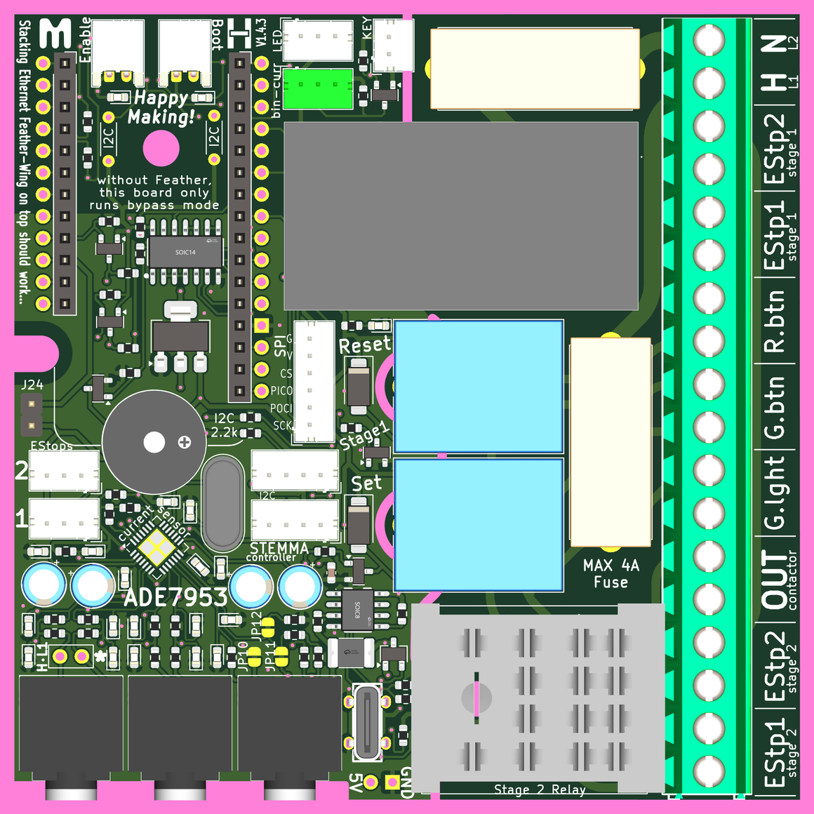
Relays (Stage 1 Set & Reset)
The twin SET and RESET relays, which make up the quinessential software controlled SR-latch for tool control are directly diven by GPIO pins. Note: when these relays have the SR-latch in the ON state, a large green light will show that the tool is powered.
switch:
  - platform: gpio
    pin: GPIO17 #A1
    name: "reset relay"
  - platform: gpio
    pin: GPIO18 #A0
    name: "set relay"
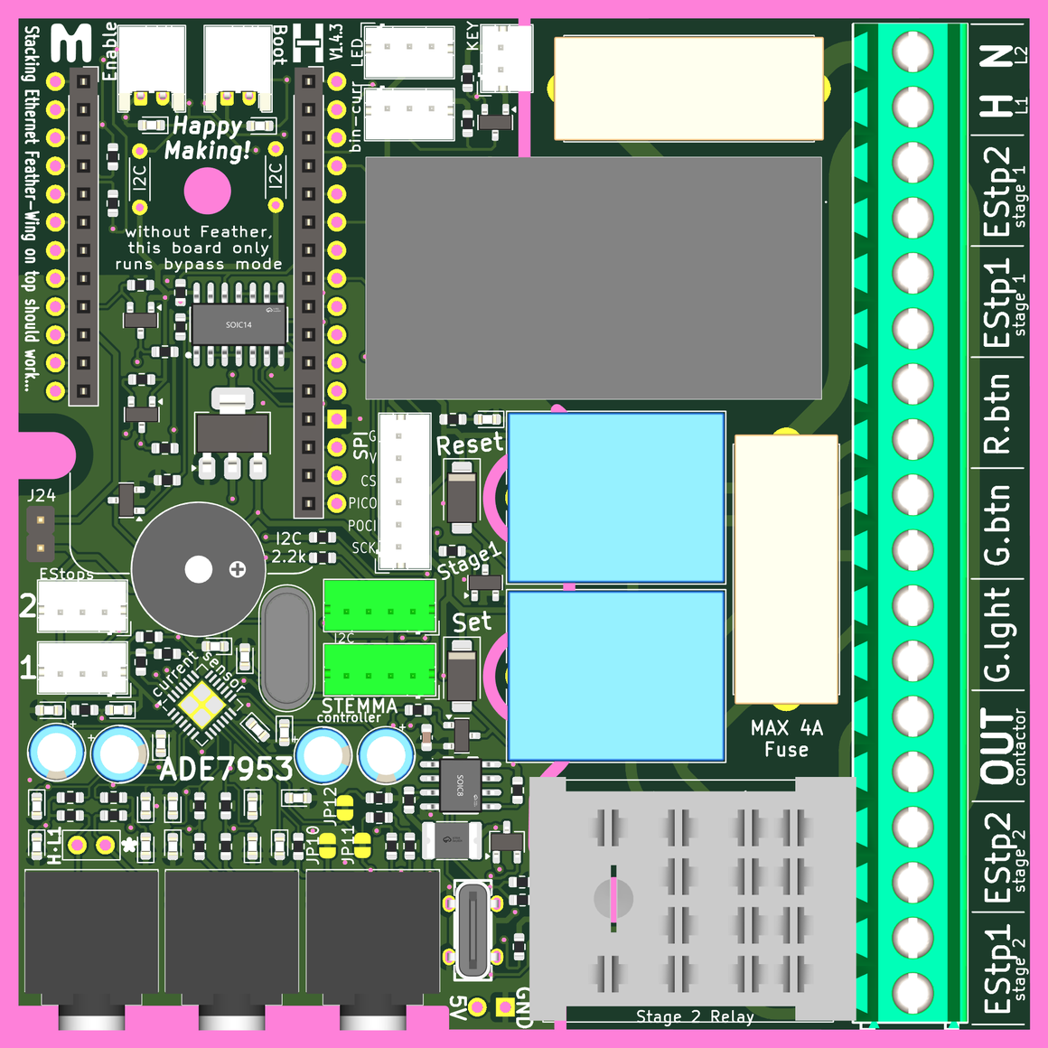
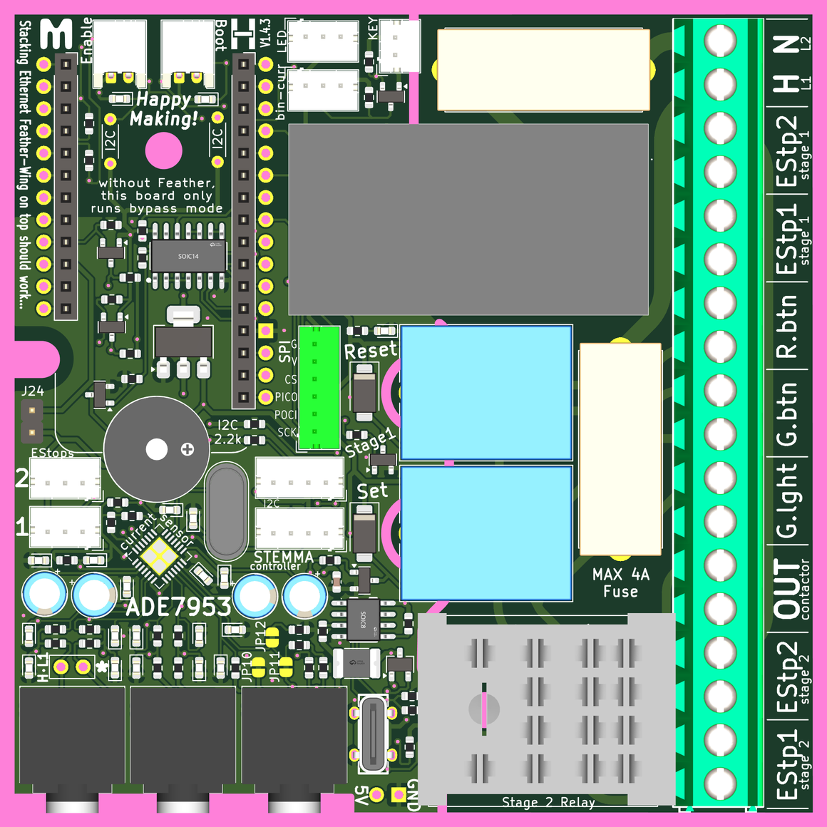
Connection for the two stage 1 relays are already hardwired in place, therefore not shown. However, the relays are in the surrounding images as light blue rectangles.
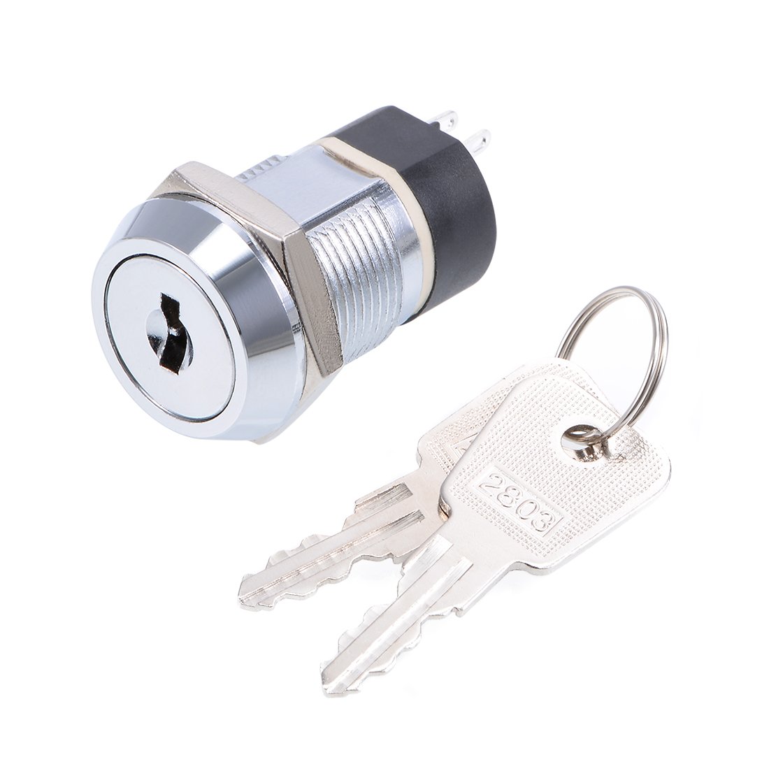
Bypass Key
This key allows someone with the key to physically override any need for software authorization. As long as the key is "on" the tool will be left in its "enabled" mode via hardwired connection to the Set relay. This will even work if there is not a Feather microcontroller placed in the wing-combo board's socket. This connects with a 2-pin JST 2.0 connector.
binary_sensor:
  - platform: gpio
    id: bypass
    name: "bypass key"
    pin:
      number: GPIO8 #A5
      inverted: true
      mode:
        input: true
        pullup: false
Red/Green Bicolor LED
The binary LED is used to show visual feedback upon RFID card read.
- RED light shows a denied RFID authorization request
- GREEN light shows an approved RFID authorization request, and a tool in "enabled" mode
- YELLOW light shows some sort of error upon RFID authorization request
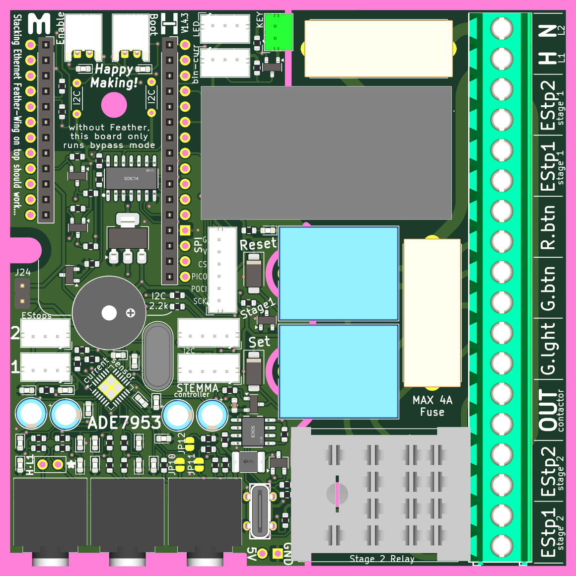
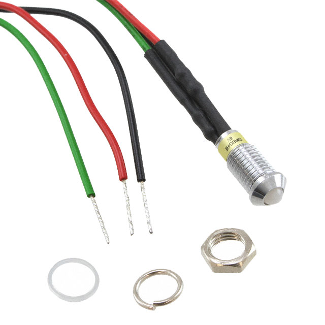
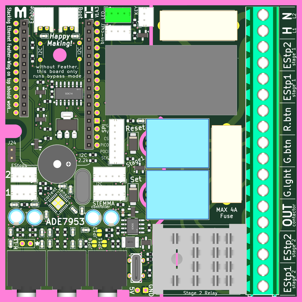
This Bicolor LED connects to a small screw terminal block on the wing-combo board.
light:
  - platform: status_led
    name: "Red LED"
    pin: GPIO5
  - platform: status_led
    name: "Green LED"
    pin: GPIO6
Location on the PCB is shown below:
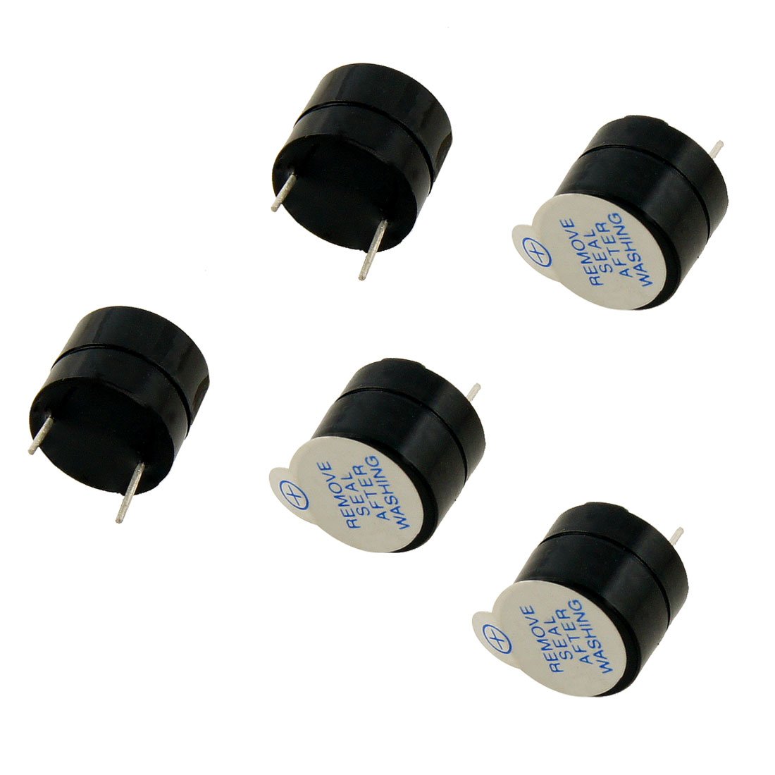
Piezo Buzzer
The buzzer is used to provide audio feedback to indicate successful card read, and the reponse state: approved, denied, or error. This is all done with RTTTL audio encoding, so simple, recognizeable sounds can be played.
output:
  - platform: ledc
    pin: GPIO16 #A2
    id: rtttl_out
rtttl:
  output: rtttl_out

"chirp: d=32,o=5,b=90: 16e,16f" # RFID read success
"no: d=32,o=5,b=90: 8b,8g,4e" # Auth request denied
"yes: d=32,o=5,b=90: 16e,16g,16b,16e,16g,16b" # Auth request approved
"part_Jeopardy: d=4,o=6,b=140: c,f,c,f5,c,f,2c,c,f,c,f,a.,8g,8f,8e,8d,8c#,c,f,c,f5,c,f,2c,f.,8d,c,a#5,a5,g5,f5" # Auth Request error
Connection for the Piezo Buzzer is already hardwired in place, therefore not shown. However, the part is in the surrounding images as a black circle with a central orange circle. Photos of these components are shown below.
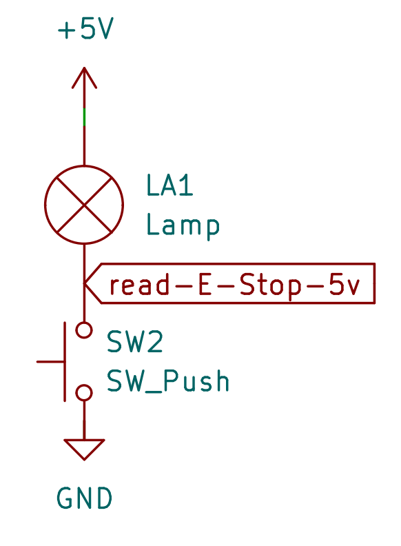
E-Stop Low-Voltage Feedback
The E-Stop is a critical part of controlling many tools. The physical buttons control a stack of electrical switches. Two red, (Normally-Closed) switches operate at high voltage, and actaully cut power to the tool if activated. However, there is a third, (Normally-Open) switch in the E-Stop that operates at 5 volts and lights a BA9S indicator LED if the E-Stop is active. The state of this 5 volt indicator light circuit is monitored through a level shifter, and provides feedback to the microcontroller about the status of the E-Stop (without needing to directly interact with the high voltage switching).
binary_sensor:
  - platform: gpio
    name: "1st E-Stop"
    pin:
      number: GPIO13
      inverted: true
      mode:
        input: true
        pullup: false
  - platform: gpio
    name: "2nd E-Stop"
    pin:
      number: GPIO12
      inverted: true
      mode:
        input: true
        pullup: false
Wiring diagram for low-voltage indicator LED and E-Stop sensing circuit. These are the three connections that go into the 3-pin JST conneciton for each E-Stop.
Location for E-Stop hookup on the PCB is shown below. Blue arrows note high-voltage connections for each E-Stop.
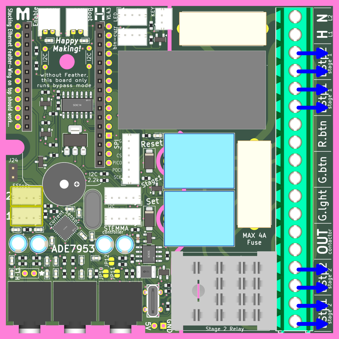
Bin-Cur | Binary Current sensing
We've found that measuring current with the ADE7953 can be a little tricky, so we've added a secondary plan. You can attach any 5-volt tolerant way to observe AC current with a binary output. That way you can have a much-simpler programming path to monitor electrical current usage. The bin-cur connector has three pins: 5v, signal and ground, but you don't need to use all of them.
[!TIP] We like using any variant of the M3050 AC Current Switch because it is relatively cheap, and easy to use.
Connect the M3050's
k1to Signal andk2to Ground and you're ready. Set the threshold with the trim potentiometer and you've got a super-simple self-powered AC monitoring solution.