SPI - TeensyUser/doc GitHub Wiki
SPI (Serial Peripheral Interface)
All ARM Teenys have at least 1 SPI bus, some have more than one.
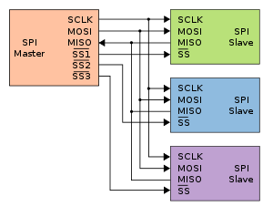
Each SPI bus has 3 dedicated pins shared with all devices on the SPI bus:
- MOSI -- data from Teensy to the device;
- MISO -- data from the device to the Teensy; (and)
- SCLK -- clock.
- Most devices have at least one additional pin per device (CS) that says the device is active. Having a CS pin means in theory the device could share a SPI bus with other devices. There are a few displays that do not have a CS pin, and that device can not share the SPI bus with other devices;
- Some SPI devices do not properly tri-state the MISO pin, which means they cannot be used on the same SPI bus as other devices without an external buffer chip (see the better SPI bus design paper);
- Some SPI devices have a D/C pin that says whether the data being sent is data or command;
- Some SPI devices have other pins, such as a reset pin.
- Some SPI devices do not use the MISO pin because they send no information back to the Teensy.
- Some SPI displays have another pin that you can attach to a Teensy PWM pin so that you can control the brightness of the display (this uses persistance of vision, where the display is rapidly turned on and off, and your eyes register it as lowering the brightness).
- The Teensy 3.1 and 3.2 pinout cards uses the name DOUT instead of MOSI, DIN instead of MISO, and SCK instead of SCLK.
SPI transactions
Newer versions of Arduino’s SPI library support transactions. Transactions give you 2 benefits:
- Each device uses their own SPI settings (SPI bus speed, bit ordering, type); (and)
- Each device gains exclusive use of the SPI bus. Other devices will not get the SPI bus until it is released.
SPI documentation and tutorials
- TI documentation
- Sparkfun tutorial
- Arduino tutorial
- Nick Gammon tutorial
- PJRC.com has a useful tutorial on Better SPI Bus Design in 3 Steps
Debugging SPI systems
- SPIdriver -- hardware to help debug SPI
- Try adjusting the SPI clock speed down for a given device if you are having random failures and glitches. This assumes you are using SPI Transactions which can vary the SPI bus speed for each device.
- Add pull-up resistors for the CS pin as mentioned in the better SPI bus design paper above.
- Keep wire lengths small, and inspect your solder joints to make sure they are solid.
First SPI bus
- On ARM Teensies, the first SPI bus uses Pin 11 (MOSI0), Pin 12 (MISO0), and Pin 13 (SCLK0) as the standard pins. This is compatible with many of the older Arduino systems.
- See the pinout cards for your Teensy for the Alternate pins (Teensy 4.0 does not have alternate SPI pins).
- If you use the revision A-C Audio shield on the Teensy 3.1, 3.2, 3.5, or 3.6 processors, you will need to use the alternate pin for MOSI0 (pin 7) and SCLK0 (pin 14), since the I2S bus used by the audio shield uses pins 11 and 13.
Special SPI pins for the Teensy 3.1, 3.2, 3.5, and 3.6
Some SPI display libraries that are specialized for the Teensy 3.1, 3.2, 3.5, and 3.6 systems have optimizations if you use one of the special pins for both the CS and the D/C pins on the first SPI bus. Several of the pins are exclusive, in that if you use one of the pins for a SPI function, you cannot use the other for a SPI function. You can use the pin for some other non-SPI use. The pins are:
- Pin 2 or pin 10;
- Pin 6 or pin 9;
- Pin 15/A1;
- Pin 20/A6 or 23/A9; (and)
- Pin 21/A7 or 22/A8.
- Explanation of these fast pins
- The Teensy 4.0 has limited optimizations for pin 10 being a special CS pin.
- The Teensy LC does not have these optimizations.